EP1321621A2 - Sonnenschutzlamelle - Google Patents
Sonnenschutzlamelle Download PDFInfo
- Publication number
- EP1321621A2 EP1321621A2 EP02023119A EP02023119A EP1321621A2 EP 1321621 A2 EP1321621 A2 EP 1321621A2 EP 02023119 A EP02023119 A EP 02023119A EP 02023119 A EP02023119 A EP 02023119A EP 1321621 A2 EP1321621 A2 EP 1321621A2
- Authority
- EP
- European Patent Office
- Prior art keywords
- cover layer
- profiles
- frame
- lamella
- sun shade
- Prior art date
- Legal status (The legal status is an assumption and is not a legal conclusion. Google has not performed a legal analysis and makes no representation as to the accuracy of the status listed.)
- Granted
Links
Images



Classifications
-
- E—FIXED CONSTRUCTIONS
- E06—DOORS, WINDOWS, SHUTTERS, OR ROLLER BLINDS IN GENERAL; LADDERS
- E06B—FIXED OR MOVABLE CLOSURES FOR OPENINGS IN BUILDINGS, VEHICLES, FENCES OR LIKE ENCLOSURES IN GENERAL, e.g. DOORS, WINDOWS, BLINDS, GATES
- E06B9/00—Screening or protective devices for wall or similar openings, with or without operating or securing mechanisms; Closures of similar construction
- E06B9/24—Screens or other constructions affording protection against light, especially against sunshine; Similar screens for privacy or appearance; Slat blinds
- E06B9/26—Lamellar or like blinds, e.g. venetian blinds
- E06B9/38—Other details
- E06B9/386—Details of lamellae
-
- E—FIXED CONSTRUCTIONS
- E06—DOORS, WINDOWS, SHUTTERS, OR ROLLER BLINDS IN GENERAL; LADDERS
- E06B—FIXED OR MOVABLE CLOSURES FOR OPENINGS IN BUILDINGS, VEHICLES, FENCES OR LIKE ENCLOSURES IN GENERAL, e.g. DOORS, WINDOWS, BLINDS, GATES
- E06B7/00—Special arrangements or measures in connection with doors or windows
- E06B7/02—Special arrangements or measures in connection with doors or windows for providing ventilation, e.g. through double windows; Arrangement of ventilation roses
- E06B7/08—Louvre doors, windows or grilles
Definitions
- the present invention relates to a solar shading with a slat frame, the opposite, extending over the length of the sunblind comprises extending profiles and these interconnecting cross braces, and a cover layer attached to the slat frame.
- Slats as a sun protection element are known from the prior art. On Example of this is disclosed in document FR 75 31456.
- the slat described here consists of preformed steel sheets, which are pressed at the ends with profiled strips are and whose interior is filled with a plastic foam. These slats are relatively heavy due to their metallic material and require a heavy support structure to hold the slats and in their angular position to adapt to the prevailing lighting conditions.
- the sunblind of the beginning mentioned type characterized in that the cover layer of a stretchable Folienund / or Fabric material consists of holders and at least one profile and / or at least one transverse strut is held stationary under prestress.
- plastic films, fiberglass fabric or comparable material to be used, which on the one hand compared to metallic Materials is extremely light, but also in thermal Fluctuations remain dimensionally stable and no wrinkles, sags or in the wind flutters.
- the thin material allows a design that still allows light to fall through can.
- the film or the fabric may be so coated or equipped that certain wavelengths are filtered out of the light. That way is it is still possible to let enough light into the building, though the heat radiation is filtered out by the sunblinds.
- the cover layer So lies in terms of their translucency between metal blades and Glass fins, but both are heavier.
- the light transmission is influenced, for example, by the mesh size of the fabric, the choice of materials and mixture and a possible coating.
- the lamellae according to the invention are inexpensive to produce.
- the holding structures can be essential be carried out more easily and cost-saving.
- the dimensions and properties the sunscreen blades according to the invention can very easily on the adapted to individual needs. With the system are different Geometries, shapes and colors can be displayed.
- a holder As a holder, various elements come into consideration. So is as a holder in particular provided a support surface on which the cover layer rests under pretension. The bias causes a frictional engagement between the cover layer and Support surface, whereby the cover layer is fixed in position. But it comes Other embodiments of a holder for the top layer into consideration, so For example, a terminal block, in which the cover layer is clamped non-positively is held, or a molded body connected to the cover layer For example, a clamping bead which can be inserted into a receiving opening, that thereby the cover layer after final assembly of the slat frame form-fitting is fixed in position under prestress.
- sun protection device Generally with 1 is a sun protection device numbered, the several sun protection slats 2 has. These sunblinds 2 are in a supporting structure 3 and in various pivoting positions, as illustrated in Fig. 1, to convict. For this they are provided with an actuating linkage 4, over the they in an upright open position and in the direction indicated in Fig. 1 closed position to be transferred.
- each sunblind 2 has a cross strut fifth with lateral profiles 6 or longitudinal edge profiles, are embedded in the grooves 7, which serve as a receptacle for the end pieces 8 and 9 respectively.
- Cross struts 5 and profiles 6 form the lamellar frame 14.
- end pieces 8 and 9 of a cover layer 10 can be used from a film material.
- This topcoat 10 is formed as a tension track, so that they the cross strut 5 as a sun protection element spans.
- the cover layer can be applied on one or both sides and be executed in one or more layers.
- the cover layer 10 is preferably made of a translucent material, the one transmits diffused light, for example with a transmittance between 10 and 20%, which ensures glare protection.
- the motor angle adjustment of the sun protection device 1 with a Sensor-based control can increase the lighting level in each office be regulated so that in interaction with artificial light consistent, glare-free Lighting conditions can be created.
- the slats can also be moved individually per room.
- cover layer 10 As material for the cover layer 10 all substances or combinations of substances come in Consider, due to their specific nature or processing, for example in a fabric, with overstretching are tensioned. This applies, for example for polyester or silicone, but also coated glass fiber fabric.
- the Glass fiber fabric can be heated and coated with PTFE, as required several times, until the required parameters such as stiffness, tear resistance, weather resistance, Fire behavior, stretch and extensibility and translucency and Optics are fulfilled.
- Spannhus is especially the burden with a tensile stress of importance, since this is the preferred in the concrete use Voltage is.
- the flexible properties of the material used It makes sense to expose the material to tensile stress, as it causes it can be kept well in shape and position.
- the cross strut 5 in Figure 2 has a central region 11, the profiles 6 after projecting beyond the top, and in the additionally still a spring element 12 are used can, which is indicated only schematically.
- a spring element 12th can in the middle of the sunblind 2, the top layer 10 also in addition be biased, but in Fig. 2 for better clarity not shown in detail.
- At least one of the end pieces 8 and 9 is as Clamping bead formed by the cover layer 10 in its position to the profile. 6 can be fixed.
- the cover layer 10 is biased to a desired degree and in If necessary also re-tensioned via the spring mechanism 11 and 12. As in Illustrated embodiment, the cover layer 10 is pulled around the profile 6 around, so that the cover layer 10, the profile 6 partially bounded.
- the boundary angle is in the embodiment about 170 °. Depending on the requirements in the application The boundary angle can also be larger or smaller. Moving around the cover layer 10 is evened out by a profile 6 or a transverse strut 5 the tension and presses the cover layer 10 on the support surface 15. In addition the voltage can be well introduced into the slat frame 14.
- the lower flange 13 ensures that according to FIG. 2 by the bias of the cover layer 10 on the crossbar 5 no vertical loads are exercised.
- a support surface 15 for the cover layer 10 serve the rounded outer contours of the profiles. 6
- An additional support surface 15 forms in the embodiment of the central region 11th
- the cover layer 10 of the corresponding film material can be the most diverse Requirements must be designed accordingly. So let's look at relative simply provide different, even multilayer film materials, the also replaced and replaced with built-in sunshade can be. This can be done with a relatively simple effort. So can also films for different seasons or in terms of design Measures find use, for example, different To realize lighting effects.
- the profiles 6 have end receptacles 16, in which the cross braces 5 are inserted.
- the Receivers 16 are preferably formed so that the crossbars 5 form fit fit into the 16 shots.
- the cross struts 5 can by screwing with the screw holes 17, which are arranged in the profiles 6 in the region of the receptacles 16 are to be connected.
- the stability of the slat frame 14 is through the combination of positive connection and additional fasteners increases and simplifies assembly.
- the profiles 6 have fastening elements 18 on which an assembly tool can be fastened. As fasteners For example, screw holes, bolts, recesses for receiving positive-locking mounts, etc. into consideration, preferably a fast attachment and allow replacement of the assembly tools.
- the slat frame 14 can be easily mounted, however, the tensioning of the cover layer 10 is more difficult.
- the clamping can be, for example be accomplished by an end piece 8, 9 with an unspecified shown tension roller is connected, the rotation of the cover layer 10 rolls up and thereby put under tension. The tension roller must then be fixed become.
- a disadvantage is the additional effort for the tensioner and the need for maintenance for moving components.
- the cover layer 10 can be light be tightened later. In this case serve as a holder, the bearing surfaces 15 and the tension roller with which the cover layer 10 is under tension is.
- the third proposed mounting method is similar to the second one, different However, by the tubular formation of the cover layer 10.
- the profiles 6 instead of the profiles. 6 insert in the hose, it is also possible, the profiles 6, for example by means bring the mounting tool in a mounting position, the hose over the Lay profiles 6 and then move the profiles apart.
- the procedure under Use of a hose forces to a double-layered cover layer 10 has the advantage that prior to moving apart of the profiles 6, the end pieces 8, 9 need not be connected to the profiles 6 and the top layer 10 exclusively positioned by the bias on the support surfaces 15 is.
- the bearing surfaces 15 thus serve as exclusive holders for the cover layer 10th
- the cover layer 10 can expand even with greater heat without that thereby loosens the top layer, wrinkles or sags.
- a sufficient Preload can be, for example, 1.5 kN, resulting in the context of Mounting can be reduced to 0.5 kN to keep the fabric taut.
- the cover layer 10 not only in one direction, but in addition in another direction.
- One down to the opposite Pages of the second direction of stress can, for example, by the assembly of Clamps are made, the cover layer 10 on elements of the slat frame 14 fix.
- the bias can also be in the second direction on here already mentioned above.
- sun shading blades 2 are shown in which the cover layer 10 is tensioned between opposite profiles 6.
- the bias can also be made by applying the topcoat 10 is held by a profile 6 and / or a transverse strut 5, wherein as Counter holder, for example, clamps or moldings for fixing the cover layer 10 can be used, which at a suitable position on the slat frame 14 are attached.
- Covering layer 10 with the help of at least one transverse profile 5 to tension.
- the transverse profiles 5 then also bearing surfaces 15, wherein as a bearing surface 15 in extreme cases, the upper edge of the profile cross-section of the transverse profile. 5 is usable.
- the methods for producing the sun protection profiles 2 can accordingly be applied.
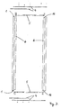
- FIG. 5 shows a side view of a sunshade lamella 2 according to the invention shown, which is provided with a tubular cover layer 10.
- the profiles 6 are held by the cross strut 5 spaced from each other.
- the actuating linkage 4 is attached.
- On the cross strut 5 can still clamping plates, Decorative lid or other elements not shown set his.
- the support structure has large spans and / or heights through a single sunblind 2 can be bridged.
- the cost of the supporting structure fall accordingly lower.
- In the unfolded position hinders the cross-sectional profile the solar shading 2 barely the view out of the building, especially with larger area coverage less sun shading 2 shading a given building surface are required.
Landscapes
- Engineering & Computer Science (AREA)
- Structural Engineering (AREA)
- Civil Engineering (AREA)
- Architecture (AREA)
- Blinds (AREA)
- Laminated Bodies (AREA)
- Building Awnings And Sunshades (AREA)
- Transition And Organic Metals Composition Catalysts For Addition Polymerization (AREA)
- Tents Or Canopies (AREA)
Abstract
Description
- Fig. 1:
- eine Seitenansicht eines Ausführungsbeispiels einer Sonnenschutzeinrichtung mit mehreren Sonnenschutzlamellen,
- Fig. 2:
- eine Querschnittsdarstellung einer Sonnenschutzlamelle der in Fig. 1 gezeigten Sonnenschutzeinrichtung,
- Fig. 3:
- eine Draufsicht auf die Einzelteile eines Lamellenrahmens,
- Fig. 4:
- einen Querschnitt durch ein Profil,
- Fig. 5:
- eine Seitenansicht auf eine erfindungsgemäße Sonnenschutzlamelle.
Claims (20)
- Sonnenschutzlamelle (2) mit einem Lamellenrahmen (14), der gegenüberliegende, sich über die Länge der Sonnenschutzlamelle (2) erstreckende Profile (6) und diese miteinander verbindende Querstreben (5) umfaßt, und mit einer am Lamellenrahmen (14) befestigten Deckschicht (10), dadurch gekennzeichnet, daß die Deckschicht (10) aus einem dehnbaren Folien- und/oder Gewebematerial besteht und von Haltern an zumindest einem Profil (6) und/oder zumindest einer Querstrebe (5) unter Vorspannung ortsfest gehalten ist.
- Sonnenschutzlamelle (2) nach Anspruch 1, dadurch gekennzeichnet, daß die Deckschicht (10) zumindest ein Profil (6) und/oder eine Querstrebe (5) des Lamellenrahmens (14) unter Vorspannung ganz oder teilweise umgrenzt.
- Sonnenschutzlamelle (2) nach Anspruch 1 oder 2, dadurch gekennzeichnet, daß die Deckschicht (10) von gegenüberliegenden Profilen (6) und/oder Querstreben (5) unter Zugspannung gehalten ist.
- Sonnenschutzlamelle (2) nach einem der vorhergehenden Ansprüche, dadurch gekennzeichnet, daß die Deckschicht (10) lichtdurchlässig ist.
- Sonnenschutzlamelle (2) nach einem der vorhergehenden Ansprüche, dadurch gekennzeichnet, daß eine Auflagefläche (15) gebildet ist von einer gerundeten Außenkontur eines Profils (6).
- Sonnenschutzlamelle (2) nach Anspruch 5, dadurch gekennzeichnet, daß die gerundete Außenkontur im Bereich der Auflagefläche (15) einen zumindest halb ellipsenförmigen Querschnitt aufweist.
- Sonnenschutzlamelle (2) nach einem der vorhergehenden Ansprüche, dadurch gekennzeichnet, daß die Deckschicht (10) zusätzlich von Auflageflächen (15) abgestützt ist, die sich zwischen den Seiten des Lamellenrahmens (14) befinden.
- Sonnenschutzlamelle (2) nach einem der vorhergehenden Ansprüche, dadurch gekennzeichnet, daß die zusätzliche Auflagefläche (15) ein auf die Deckschicht (10) einwirkendes Federelement aufweist.
- Sonnenschutzlamelle (2) nach einem der vorhergehenden Ansprüche, dadurch gekennzeichnet, daß die Deckschicht (10) als Bahn ausgebildet ist und die Endstücke (8, 9) der Bahn an dem Lamellenrahmen (14) festlegbar sind.
- Sonnenschutzlamelle (2) nach einem der vorhergehenden Ansprüche, dadurch gekennzeichnet, daß die Profile (6) zumindest eine Aufnahme (7) aufweisen, in die Endstücke (8, 9) der Bahn einsetzbar sind.
- Sonnenschutzlamelle (2) nach einem der vorhergehenden Ansprüche, dadurch gekennzeichnet, daß zumindest ein Endstück (8, 9) als eine die Bahn aufrollende und spannende Spannrolle ausgebildet ist.
- Sonnenschutzlamelle (2) nach einem der vorhergehenden Ansprüche 1 bis 10, dadurch gekennzeichnet, daß die Endstücke (8, 9) der Bahn mit Befestigungsmitteln an den Profilen fixiert sind und eine Verstellung der Vorspannung nur durch eine Veränderung des Abstands der Profile (6) zueinander möglich ist.
- Sonnenschutzlamelle (2) nach einem der vorhergehenden Ansprüche 1 bis 8, dadurch gekennzeichnet, daß die Deckschicht (10) schlauchförmig ausgebildet ist, wobei die Deckschicht (10) durch die Vorspannung ohne zusätzliche Befestigungselemente ortsfest auf den Auflageflächen (15) gehalten ist.
- Sonnenschutzlamelle (2) nach Anspruch 13, dadurch gekennzeichnet, daß die schlauchförmige Deckschicht (10) aus einer Bahn von flacher Folie und/oder Gewebe gebildet ist, deren gegenüberliegende Kanten miteinander verbunden sind.
- Sonnenschutzlamelle (2) nach einem der vorhergehenden Ansprüche, dadurch gekennzeichnet, daß die Profile (6) stirnseitig Befestigungselemente (18) zur Befestigung eines Montagewerkzeugs aufweisen.
- Sonnenschutzlamelle (2) nach einem der vorhergehenden Ansprüche, dadurch gekennzeichnet, daß die Profile (6) Befestigungspunkte (17) zur Befestigung der Querstreben (6) aufweisen.
- Sonnenschutzlamelle (2) nach einem der vorhergehenden Ansprüche, dadurch gekennzeichnet, daß die Profile (6) stirnseitige Aufnahmen (16), in die die Querstreben (5) eingelegt sind, aufweisen.
- Sonnenschutzlamelle (2) nach Anspruch 15, dadurch gekennzeichnet, daß die Aufnahmen (16) im Verhältnis zur Form und Dicke der Querstreben (5) so ausgebildet sind, daß die nach außen gewandte Oberfläche der montierten Querstreben (5) mit der übrigen Stirnfläche der Profile (6) eine gemeinsame plane Oberfläche bilden.
- Verfahren zur Herstellung einer Sonnenschutzlamelle (2) mit einem Rahmen und einer Deckschicht, dadurch gekennzeichnet, daß entweder in eine schlauchförmige Deckschicht Profile (6) eingelegt werden oder die Endstücke (8, 9) einer aus einer Bahn bestehenden Deckschicht (10) an Profilen (6) befestigt werden, diese Profile (6) auseinander bewegt werden, wodurch die Deckschicht (10) vorgespannt wird und sich mit seiner Innenseite auf Auflageflächen (15) der Profile (6) auflegt, und die Profile (6) sodann durch Querstreben (5) in einer Lage fixiert sind, in denen eine Vorspannung der Deckschicht (10) erhalten bleibt.
- Verfahren zur Herstellung einer Sonnenschutzlamelle (2) mit einem Lamellenrahmen (14) und einer Deckschicht (10), dadurch gekennzeichnet, daß eine Deckschicht (10) auf einen Lamellenrahmen (14) aufgelegt wird und die Deckschicht (10) vorgespannt wird, indem zumindest ein Endstück (8, 9) der Deckschicht (10) am Lamellenrahmen (14) fixiert wird und das andere Endstück (8, 9) mittels einer als Spannelement ausgebildeten Aufrollvorrichtung unter Zugspannung versetzt und auf der gegenüberliegenden Seite des Lamellenrahmens festgelegt wird.
Applications Claiming Priority (2)
| Application Number | Priority Date | Filing Date | Title |
|---|---|---|---|
| DE10163499 | 2001-12-21 | ||
| DE10163499 | 2001-12-21 |
Publications (4)
| Publication Number | Publication Date |
|---|---|
| EP1321621A2 true EP1321621A2 (de) | 2003-06-25 |
| EP1321621A3 EP1321621A3 (de) | 2004-01-02 |
| EP1321621B1 EP1321621B1 (de) | 2011-07-20 |
| EP1321621B8 EP1321621B8 (de) | 2012-02-15 |
Family
ID=7710531
Family Applications (1)
| Application Number | Title | Priority Date | Filing Date |
|---|---|---|---|
| EP02023119A Expired - Lifetime EP1321621B8 (de) | 2001-12-21 | 2002-10-15 | Sonnenschutzlamelle |
Country Status (2)
| Country | Link |
|---|---|
| EP (1) | EP1321621B8 (de) |
| AT (1) | ATE517221T1 (de) |
Cited By (4)
| Publication number | Priority date | Publication date | Assignee | Title |
|---|---|---|---|---|
| DE102004030086A1 (de) * | 2004-06-22 | 2006-01-12 | Schollglas Holding- und Geschäftsführungsgesellschaft mbH | Verglasungselement im Sandwichaufbau |
| EP2687648A1 (de) * | 2012-07-20 | 2014-01-22 | Urban Green Design, S.L. | Freitragende Struktur zum Tragen von Lamellen für Fassaden |
| CN107989240A (zh) * | 2017-12-14 | 2018-05-04 | 上海玻机智能幕墙股份有限公司 | 一种大截面大跨度遮阳百叶安装结构 |
| US10030440B2 (en) | 2013-12-13 | 2018-07-24 | Mare Beheer B.V. | Venetian blind |
Citations (3)
| Publication number | Priority date | Publication date | Assignee | Title |
|---|---|---|---|---|
| AT241782B (de) | 1962-07-25 | 1965-08-10 | Aluminium Ind Ag | Metallische, hohle Sonnenschutzlamelle |
| FR2327385A1 (fr) | 1975-10-08 | 1977-05-06 | Danto Rogeat Et Cie | Lame pour l'occultation totale ou partielle de surfaces vitrees |
| DE29722219U1 (de) | 1997-12-16 | 1998-02-12 | DIPA-NORD GmbH, 23843 Bad Oldesloe | Lamelle für ein Sonnen- und/oder Wärmeschutzsystem |
Family Cites Families (1)
| Publication number | Priority date | Publication date | Assignee | Title |
|---|---|---|---|---|
| US5358024A (en) * | 1990-01-02 | 1994-10-25 | The Geon Company | Web covered vertical blind slat assemblies |
-
2002
- 2002-10-15 EP EP02023119A patent/EP1321621B8/de not_active Expired - Lifetime
- 2002-10-15 AT AT02023119T patent/ATE517221T1/de active
Patent Citations (3)
| Publication number | Priority date | Publication date | Assignee | Title |
|---|---|---|---|---|
| AT241782B (de) | 1962-07-25 | 1965-08-10 | Aluminium Ind Ag | Metallische, hohle Sonnenschutzlamelle |
| FR2327385A1 (fr) | 1975-10-08 | 1977-05-06 | Danto Rogeat Et Cie | Lame pour l'occultation totale ou partielle de surfaces vitrees |
| DE29722219U1 (de) | 1997-12-16 | 1998-02-12 | DIPA-NORD GmbH, 23843 Bad Oldesloe | Lamelle für ein Sonnen- und/oder Wärmeschutzsystem |
Cited By (5)
| Publication number | Priority date | Publication date | Assignee | Title |
|---|---|---|---|---|
| DE102004030086A1 (de) * | 2004-06-22 | 2006-01-12 | Schollglas Holding- und Geschäftsführungsgesellschaft mbH | Verglasungselement im Sandwichaufbau |
| EP2687648A1 (de) * | 2012-07-20 | 2014-01-22 | Urban Green Design, S.L. | Freitragende Struktur zum Tragen von Lamellen für Fassaden |
| ES2439621R1 (es) * | 2012-07-20 | 2014-03-31 | Urban Green Design, S.L | Estructura autoportante para el soporte de lamas para fachadas de edificios |
| US10030440B2 (en) | 2013-12-13 | 2018-07-24 | Mare Beheer B.V. | Venetian blind |
| CN107989240A (zh) * | 2017-12-14 | 2018-05-04 | 上海玻机智能幕墙股份有限公司 | 一种大截面大跨度遮阳百叶安装结构 |
Also Published As
| Publication number | Publication date |
|---|---|
| EP1321621B8 (de) | 2012-02-15 |
| EP1321621B1 (de) | 2011-07-20 |
| EP1321621A3 (de) | 2004-01-02 |
| ATE517221T1 (de) | 2011-08-15 |
Similar Documents
| Publication | Publication Date | Title |
|---|---|---|
| DE19739919C2 (de) | Sonnenrollo für ein Kraftfahrzeugdach | |
| DE69516874T2 (de) | Pflanzenschutzvorrichtung mit faltbarem wasserdichten pflanzenschutzvorhang | |
| EP1848932A1 (de) | Gestell zur anordnung von solarmodulen | |
| DE102011122502B4 (de) | Bedachung mit Spannelement | |
| DE60319622T2 (de) | Ausrichtung zum Installieren einer Markise | |
| WO1998011807A1 (de) | Federbrücke für eine untermatratze | |
| DE10102799C1 (de) | Schutz- und/oder Abdeckrollo für Fahrzeuge, wie z. B. Lichtschutz-Fensterrollo, Laderaum-Abdeckrollo, od.dgl. | |
| DE2208822A1 (de) | Halterung fuer kunststoffolien zur ueberspannung von rahmenkonstruktionen | |
| EP1321621B1 (de) | Sonnenschutzlamelle | |
| DE3512134A1 (de) | Aufrollbare abdeckung fuer becken, insbesondere schwimmbecken | |
| DE69226614T2 (de) | Unsichtbare Verbindungsvorrichtung, insbesondere anwendbar für gespannte Leinwände | |
| DE4328674A1 (de) | Verkleidungsdeckel für Kraftfahrzeug-Schiebedächer | |
| DE202012100656U1 (de) | Parallel raffbares Membrandach | |
| DE19707607A1 (de) | Einrichtung mit einem verstellbaren Organ zum Schutz gegen Licht und/oder Witterung und/oder Einbruch und/oder zum Umlenken von Licht | |
| DE19928613C2 (de) | Abschlußstab für einen flexiblen, ausziehbaren Behang | |
| EP1452661B1 (de) | Beschattungssystem | |
| DE102013019243B4 (de) | Seilbremse, Spannset und Vorhangsystem | |
| EP0330086A1 (de) | Vorrichtung zum Verbinden mindestens zweier längsausgedehnter im wesentlichen gerader Randpartien von Folien- oder gewebeartigen Gebilden | |
| WO2004090266A1 (de) | Membran-wandelement für die errichtung einer zelt-oder hallenkonstruktion | |
| DE102007002857B4 (de) | Rolloanordnung mit Führungselement | |
| DE3049841C2 (de) | ||
| DE102017218088B4 (de) | Schutzvorrichtung für einen Fahrzeuginnenraum | |
| DE202005002523U1 (de) | Gestell zur Anordnung von Solarmodulen | |
| DE112013006631T5 (de) | Kunststoffprofil für einen steifen Tragkörper | |
| DE3107404A1 (de) | "abdeckvorrichtung, insbesondere fuer schraege dachflaechenfenster" |
Legal Events
| Date | Code | Title | Description |
|---|---|---|---|
| PUAI | Public reference made under article 153(3) epc to a published international application that has entered the european phase |
Free format text: ORIGINAL CODE: 0009012 |
|
| AK | Designated contracting states |
Designated state(s): AT BE BG CH CY CZ DE DK EE ES FI FR GB GR IE IT LI LU MC NL PT SE SK TR |
|
| AX | Request for extension of the european patent |
Extension state: AL LT LV MK RO SI |
|
| PUAL | Search report despatched |
Free format text: ORIGINAL CODE: 0009013 |
|
| AK | Designated contracting states |
Kind code of ref document: A3 Designated state(s): AT BE BG CH CY CZ DE DK EE ES FI FR GB GR IE IT LI LU MC NL PT SE SK TR |
|
| AX | Request for extension of the european patent |
Extension state: AL LT LV MK RO SI |
|
| RIC1 | Information provided on ipc code assigned before grant |
Ipc: 7E 06B 7/084 A Ipc: 7E 06B 9/386 B |
|
| 17P | Request for examination filed |
Effective date: 20040514 |
|
| AKX | Designation fees paid |
Designated state(s): AT CH DE GB LI |
|
| GRAP | Despatch of communication of intention to grant a patent |
Free format text: ORIGINAL CODE: EPIDOSNIGR1 |
|
| GRAS | Grant fee paid |
Free format text: ORIGINAL CODE: EPIDOSNIGR3 |
|
| GRAA | (expected) grant |
Free format text: ORIGINAL CODE: 0009210 |
|
| AK | Designated contracting states |
Kind code of ref document: B1 Designated state(s): AT CH DE GB LI |
|
| REG | Reference to a national code |
Ref country code: GB Ref legal event code: FG4D Free format text: NOT ENGLISH |
|
| REG | Reference to a national code |
Ref country code: CH Ref legal event code: EP |
|
| RAP2 | Party data changed (patent owner data changed or rights of a patent transferred) |
Owner name: COLT INTERNATIONAL LICENSING LIMITED |
|
| REG | Reference to a national code |
Ref country code: DE Ref legal event code: R096 Ref document number: 50215131 Country of ref document: DE Effective date: 20110908 |
|
| REG | Reference to a national code |
Ref country code: DE Ref legal event code: R081 Ref document number: 50215131 Country of ref document: DE Owner name: COLT INTERNATIONAL LICENSING LTD., HAVANT, GB Free format text: FORMER OWNER: COLT INTERNATIONAL HOLDINGS AG, BAAR, CH Effective date: 20110719 Ref country code: DE Ref legal event code: R081 Ref document number: 50215131 Country of ref document: DE Owner name: COLT INTERNATIONAL LICENSING LTD., HAVANT, GB Free format text: FORMER OWNER: COLT INTERNATIONAL HOLDINGS AG, BAAR, CH Effective date: 20110929 |
|
| REG | Reference to a national code |
Ref country code: CH Ref legal event code: NV Representative=s name: SCHNEIDER FELDMANN AG PATENT- UND MARKENANWAELTE |
|
| PLBE | No opposition filed within time limit |
Free format text: ORIGINAL CODE: 0009261 |
|
| STAA | Information on the status of an ep patent application or granted ep patent |
Free format text: STATUS: NO OPPOSITION FILED WITHIN TIME LIMIT |
|
| 26N | No opposition filed |
Effective date: 20120423 |
|
| REG | Reference to a national code |
Ref country code: DE Ref legal event code: R097 Ref document number: 50215131 Country of ref document: DE Effective date: 20120423 |
|
| PGFP | Annual fee paid to national office [announced via postgrant information from national office to epo] |
Ref country code: AT Payment date: 20181019 Year of fee payment: 17 |
|
| PGFP | Annual fee paid to national office [announced via postgrant information from national office to epo] |
Ref country code: GB Payment date: 20181025 Year of fee payment: 17 Ref country code: CH Payment date: 20181025 Year of fee payment: 17 |
|
| PGFP | Annual fee paid to national office [announced via postgrant information from national office to epo] |
Ref country code: DE Payment date: 20190903 Year of fee payment: 18 |
|
| REG | Reference to a national code |
Ref country code: CH Ref legal event code: PL |
|
| PG25 | Lapsed in a contracting state [announced via postgrant information from national office to epo] |
Ref country code: LI Free format text: LAPSE BECAUSE OF NON-PAYMENT OF DUE FEES Effective date: 20191031 Ref country code: CH Free format text: LAPSE BECAUSE OF NON-PAYMENT OF DUE FEES Effective date: 20191031 |
|
| REG | Reference to a national code |
Ref country code: AT Ref legal event code: MM01 Ref document number: 517221 Country of ref document: AT Kind code of ref document: T Effective date: 20191015 |
|
| GBPC | Gb: european patent ceased through non-payment of renewal fee |
Effective date: 20191015 |
|
| PG25 | Lapsed in a contracting state [announced via postgrant information from national office to epo] |
Ref country code: GB Free format text: LAPSE BECAUSE OF NON-PAYMENT OF DUE FEES Effective date: 20191015 |
|
| PG25 | Lapsed in a contracting state [announced via postgrant information from national office to epo] |
Ref country code: AT Free format text: LAPSE BECAUSE OF NON-PAYMENT OF DUE FEES Effective date: 20191015 |
|
| REG | Reference to a national code |
Ref country code: DE Ref legal event code: R119 Ref document number: 50215131 Country of ref document: DE |
|
| PG25 | Lapsed in a contracting state [announced via postgrant information from national office to epo] |
Ref country code: DE Free format text: LAPSE BECAUSE OF NON-PAYMENT OF DUE FEES Effective date: 20210501 |