EP1321638A1 - Système de degasage pou le carter d'un moteur à combustion interne - Google Patents
Système de degasage pou le carter d'un moteur à combustion interne Download PDFInfo
- Publication number
- EP1321638A1 EP1321638A1 EP01850220A EP01850220A EP1321638A1 EP 1321638 A1 EP1321638 A1 EP 1321638A1 EP 01850220 A EP01850220 A EP 01850220A EP 01850220 A EP01850220 A EP 01850220A EP 1321638 A1 EP1321638 A1 EP 1321638A1
- Authority
- EP
- European Patent Office
- Prior art keywords
- crankcase
- cylinders
- cylinder
- engine
- cylinder block
- Prior art date
- Legal status (The legal status is an assumption and is not a legal conclusion. Google has not performed a legal analysis and makes no representation as to the accuracy of the status listed.)
- Withdrawn
Links
- 238000002485 combustion reaction Methods 0.000 title claims abstract description 16
- 230000029058 respiratory gaseous exchange Effects 0.000 title 1
- 238000009423 ventilation Methods 0.000 claims abstract description 49
- 230000001050 lubricating effect Effects 0.000 claims abstract description 4
- 239000003570 air Substances 0.000 description 14
- 230000010349 pulsation Effects 0.000 description 7
- 239000007789 gas Substances 0.000 description 4
- 239000000446 fuel Substances 0.000 description 3
- 239000002245 particle Substances 0.000 description 2
- 239000012080 ambient air Substances 0.000 description 1
- 238000005266 casting Methods 0.000 description 1
- 238000004519 manufacturing process Methods 0.000 description 1
- 230000002787 reinforcement Effects 0.000 description 1
- 238000000926 separation method Methods 0.000 description 1
Images


Classifications
-
- F—MECHANICAL ENGINEERING; LIGHTING; HEATING; WEAPONS; BLASTING
- F01—MACHINES OR ENGINES IN GENERAL; ENGINE PLANTS IN GENERAL; STEAM ENGINES
- F01M—LUBRICATING OF MACHINES OR ENGINES IN GENERAL; LUBRICATING INTERNAL COMBUSTION ENGINES; CRANKCASE VENTILATING
- F01M11/00—Component parts, details or accessories, not provided for in, or of interest apart from, groups F01M1/00 - F01M9/00
- F01M11/02—Arrangements of lubricant conduits
Definitions
- the present invention relates to an internal combustion engine comprising a cylinder block; a cylinder head mounted upon the cylinder block; a crankcase containing a supply of oil for lubricating the engine; at least one crankcase ventilation passage extending from the crankcase at a position which is above the oil level and through the cylinder block and the cylinder head.
- crankcase ventilation arrangement to reduce the over pressure in the crankcase resulting from the reciprocating movement of the pistons in the cylinders.
- the crankcase defines a space beneath the cylinders and above the oil level in the crankcase. In this space air may be mixed with oil to moisture which must be prevented to reach the ambient air when the crankcase is ventilated. Also a small portion of the working gases may escape from the combustion chamber past the piston rings to the crankcase. These gases are referred to as blow-by.
- the crankcase ventilation arrangement is connected to the intake system which in turn is connected to the cylinders and the combustion chambers. Any oil moisture and blow-by gases are ventilated through the crankcase ventilation arrangement and are in this way recycled through the combustion process.
- a known crankcase ventilation arrangement for an internal combustion engine is disclosed in US,A,4 493 295.
- Two vertically arranged ventilation passages extend from the crankcase, through the cylinder block and the cylinder head and end under the camshaft cover.
- Oil return channels extend parallel to the ventilation passages and are separated from the ventilation passages. When the ventilation passages are separated from the oil returning channels oil returning from the cylinder head is prevented from being mixed with the ventilated air.
- the present solution to the problems caused by the pressure pulsations is to reduce or eliminate the pulsations and thereby increase the engine power and reduce the fuel and oil consumption.
- the crankcase ventilation passage is connected to at least two cylinders the pulses created from one of the pistons in one of the cylinders will be equalized when the air is free to flow into the other cylinder and vice versa.
- the three-way termination is located near the bottom dead center (B.D.C) of the cylinder.
- B.D.C bottom dead center
- Fig. 1 is an exploded view in perspective of an internal combustion engine 1 according to the present invention.
- the internal combustion engine 1 is in this embodiment an inline-6 cylinder engine.
- the engine 1 comprises a cylinder block 2, a cylinder head 3 mounted upon the cylinder block 2 and a camshaft cover 4 arranged above the cylinder head 3.
- the cylinder head 3 is only partly disclosed in Fig. 1.
- a crankcase 5 is formed in the bottom part of the cylinder block 2 .
- the crankcase 5 defines a space containing a supply of oil for lubricating the engine.
- the cylinder block 2 is provided with six cylinder bores 7 in which reciprocating pistons 8 are arranged. Also the cylinder head 3 is provided with cylinder bores 7. On the outside of the cylinder block 2 lots of reinforcement ribs 9 are arranged.
- the engine 1 is provided with a crankcase ventilation arrangement 10 to reduce the over pressure in the crankcase 5 resulting from the reciprocating movement of the pistons 8 in the cylinders bores 7.
- the cylinder block 2 according to the embodiment disclosed in Fig. 1 is provided with five vertically arranged crankcase ventilation passages 11. Due to the manufacturing process of the cylinder block 2, preferably casting, the vertically passages 11 are tapered. Each vertical passage 11 extends from the crankcase 5 at a position which is above the oil level in the crankcase and through the cylinder block 2 and the cylinder head 3. Each passage emerging from the cylinder head 3 under the camshaft cover 4 arranged above the cylinder head 3.
- the crankcase ventilation arrangement 10 is connected to the intake system 12 of the engine 1 which in turn is connected to the cylinders 7 and the combustion chambers 13. In this way any oil moisture and blow-by gases ventilated through the crankcase ventilation arrangement 10 are recycled through the combustion process.
- the cover 4 arranged over the cylinder head 3 is provided with an opening 6 for connecting the space under the cover 4 to the intake system 12 of the engine 1.
- the engine is provided with a schematically disclosed turbo charger 14 and the ventilation arrangement 10 is connected to the inlet 15 of the turbo charger 14.
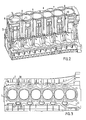
- a cylinder block 2 according to the present invention is disclosed in a partly cutout view in perspective.
- Five vertical ventilation passages 11 are arranged in the cylinder block 2.
- Each ventilation passage 11 is arranged substantially between and offset to two cylinders 7, so that each ventilation passage 11 is connected by the three-way termination 17 to two cylinders 7.
- This connection is illustrated with the double directed arrows in Fig. 2. Since each passage 11 is connected to two cylinders 7 all cylinders 7 are connected to each other. Therefore, pulses created from one of the pistons 8 in one of the cylinders 7 will be equalized when the air is free to flow into the other cylinders 7 and vice versa.
- the three-way termination 17 is located near the bottom dead center (B.D.C) of the cylinder 7.
- the pulsating air created by the underside of the pistons 8 will be directed immediately into the ventilation passages 11 via the three-way terminations 17.
- the amount of ventilation passages 11 corresponds to or is less than the amount of cylinders 7. Therefore, it may be six ventilation passages 11 arranged in the cylinder block 2 when there are six cylinders 7 present in the engine.
- the two central pistons 8 are moving together side-by-side and therefore a central ventilation passage 11 is not needed, since the two central pistons 8 cannot compensate each others movement.
- only four ventilation passages 11 are needed in an inline-six cylinder engine. In an inline-five cylinder engine there will be four ventilation passages 11 and in an inline-four cylinder engine there will be three or just two ventilation passages 11.
- Fig. 3 is a view from above of the cylinder block 2 according to the present invention. From this figure it is evident how the vertical ventilation passages 11 are arranged substantially between and offset to the cylinders 7. On the opposite side to the row of cylinders 7, four oil drainage passages 16 are arranged in the block 2. The oil drainage passages 16 extend essentially parallel to the ventilation passages 11 and are in this way separated from the ventilation passages 11. As a result of this separation oil returning from the cylinder head 3 and into the crankcase 5 is prevented from being mixed with the ventilated air in the ventilation passages 11.
- openings 19 are arranged in the cylinder walls 20 in a position beneath the bottom dead center (B.D.C.) in the cylinder 7.
- the openings 19 have a common centerline 21, which extends in the same direction as the row of cylinders 7.
- the object of the openings is to reduce or eliminate the pulsations in the ventilated air.
- crankcase ventilation arrangement 10 in the internal combustion engine 1 according to the present invention will be described.
- the reciprocating movement of the pistons 8 in the cylinders 7 will generate a pulsating over pressure in the crankcase 5.
- the over pressure creates an airflow in the three-way terminations 17, which connects to the vertical passages 11 to the cylinders.
- the air flows upwards in the vertical passages 11 in the cylinder block 2 and into the vertical passages 11 formed in the cylinder head 3.
- pulses created from one of the pistons 8 in one of the cylinders 7 will be equalized when the air is free to flow into the other cylinders 7 and vice versa.
- the pressure pulses in the crankcase 5 and in the vertical passages 11 will be reduced or eliminated.
- the air in the vertical passages 11 flows into the space defined under the camshaft cover 4 and further out of the opening 6 arranged in the wall of the cover 4. From the opening 6 the air is guided to the intake system 12 of the engine 1 via the turbo charger 14.
Landscapes
- Engineering & Computer Science (AREA)
- Mechanical Engineering (AREA)
- General Engineering & Computer Science (AREA)
- Cylinder Crankcases Of Internal Combustion Engines (AREA)
Priority Applications (2)
| Application Number | Priority Date | Filing Date | Title |
|---|---|---|---|
| EP01850220A EP1321638A1 (fr) | 2001-12-21 | 2001-12-21 | Système de degasage pou le carter d'un moteur à combustion interne |
| US10/248,141 US20030116147A1 (en) | 2001-12-21 | 2002-12-20 | A crankcase ventilation system for an internal combustion engine |
Applications Claiming Priority (1)
| Application Number | Priority Date | Filing Date | Title |
|---|---|---|---|
| EP01850220A EP1321638A1 (fr) | 2001-12-21 | 2001-12-21 | Système de degasage pou le carter d'un moteur à combustion interne |
Publications (1)
| Publication Number | Publication Date |
|---|---|
| EP1321638A1 true EP1321638A1 (fr) | 2003-06-25 |
Family
ID=8184905
Family Applications (1)
| Application Number | Title | Priority Date | Filing Date |
|---|---|---|---|
| EP01850220A Withdrawn EP1321638A1 (fr) | 2001-12-21 | 2001-12-21 | Système de degasage pou le carter d'un moteur à combustion interne |
Country Status (2)
| Country | Link |
|---|---|
| US (1) | US20030116147A1 (fr) |
| EP (1) | EP1321638A1 (fr) |
Families Citing this family (5)
| Publication number | Priority date | Publication date | Assignee | Title |
|---|---|---|---|---|
| US20060130479A1 (en) * | 2004-12-21 | 2006-06-22 | Holm Christopher E | Turbocharger with blow-by gas injection port |
| KR100765584B1 (ko) * | 2006-11-20 | 2007-10-09 | 현대자동차주식회사 | 크랭크케이스의 환기장치 |
| US9593605B2 (en) * | 2012-09-17 | 2017-03-14 | Ford Global Technologies, Llc | Crankcase ventilation via crankcase pulsation |
| CN110067667A (zh) * | 2019-06-03 | 2019-07-30 | 广西玉柴机器股份有限公司 | V型气缸体的除气孔结构 |
| CN114087443B (zh) * | 2021-09-30 | 2023-07-14 | 嘉兴迈思特管件制造有限公司 | 一种风力发电机曲轴箱通风管用接头结构 |
Citations (6)
| Publication number | Priority date | Publication date | Assignee | Title |
|---|---|---|---|---|
| JPS5713228A (en) * | 1980-06-28 | 1982-01-23 | Yamaha Motor Co Ltd | Intake system of multi cylinder engine |
| EP0240120A2 (fr) * | 1986-03-15 | 1987-10-07 | Austin Rover Group Limited | Moteur à combustion interne |
| DE3727073A1 (de) * | 1986-08-27 | 1988-03-03 | Volkswagen Ag | Kurbelgehaeuse fuer eine brennkraftmaschine mit einem entlueftungskanal |
| US4771745A (en) * | 1986-03-22 | 1988-09-20 | Mitsubishi Jidosha Kogyo Kabushiki Kaishi | Structure of internal combustion engine |
| JPH11200831A (ja) * | 1998-01-19 | 1999-07-27 | Isuzu Motors Ltd | V型エンジンのブローバイガス通路構造 |
| JPH11223118A (ja) * | 1998-02-05 | 1999-08-17 | Suzuki Motor Corp | エンジンのブロ−バイガス通路 |
Family Cites Families (1)
| Publication number | Priority date | Publication date | Assignee | Title |
|---|---|---|---|---|
| US5669366A (en) * | 1996-07-10 | 1997-09-23 | Fleetguard, Inc. | Closed crankcase ventilation system |
-
2001
- 2001-12-21 EP EP01850220A patent/EP1321638A1/fr not_active Withdrawn
-
2002
- 2002-12-20 US US10/248,141 patent/US20030116147A1/en not_active Abandoned
Patent Citations (6)
| Publication number | Priority date | Publication date | Assignee | Title |
|---|---|---|---|---|
| JPS5713228A (en) * | 1980-06-28 | 1982-01-23 | Yamaha Motor Co Ltd | Intake system of multi cylinder engine |
| EP0240120A2 (fr) * | 1986-03-15 | 1987-10-07 | Austin Rover Group Limited | Moteur à combustion interne |
| US4771745A (en) * | 1986-03-22 | 1988-09-20 | Mitsubishi Jidosha Kogyo Kabushiki Kaishi | Structure of internal combustion engine |
| DE3727073A1 (de) * | 1986-08-27 | 1988-03-03 | Volkswagen Ag | Kurbelgehaeuse fuer eine brennkraftmaschine mit einem entlueftungskanal |
| JPH11200831A (ja) * | 1998-01-19 | 1999-07-27 | Isuzu Motors Ltd | V型エンジンのブローバイガス通路構造 |
| JPH11223118A (ja) * | 1998-02-05 | 1999-08-17 | Suzuki Motor Corp | エンジンのブロ−バイガス通路 |
Also Published As
| Publication number | Publication date |
|---|---|
| US20030116147A1 (en) | 2003-06-26 |
Similar Documents
| Publication | Publication Date | Title |
|---|---|---|
| US6112708A (en) | Stratified scavenging two-cycle engine | |
| EP0471886B1 (fr) | Système de ventilation pour un moteur d'automobile à combustion interne | |
| US7506629B2 (en) | Oil return structure for internal combustion engine | |
| JP3389801B2 (ja) | エンジンのブローバイガス還元構造 | |
| US6202603B1 (en) | Internal combustion engine | |
| EP1498588A3 (fr) | Moteur à combustion interne à deux temps | |
| JP2013113109A (ja) | 内燃機関のヘッドカバー構造 | |
| US6920869B2 (en) | V-type engine | |
| US20030116147A1 (en) | A crankcase ventilation system for an internal combustion engine | |
| EP0698181B1 (fr) | Systeme d'induction pour moteur a combustion interne | |
| US4712532A (en) | Crankcase emission control system for an internal combustion engine | |
| US7044117B2 (en) | Positive crankcase ventilation system | |
| JPS6244082Y2 (fr) | ||
| JP3832531B2 (ja) | エンジンのブロ−バイガス通路 | |
| WO2004111400B1 (fr) | Collecteur d'echappement et moteur a combustion interne comprenant un collecteur d'echappement | |
| US6516764B2 (en) | Camshaft supporting structure for four-stroke cycle engine | |
| JP2005220883A (ja) | エンジンの上部体構造 | |
| JPH0752324Y2 (ja) | エンジンのブローバイガス通路 | |
| US20250230767A1 (en) | Two-stroke engine for a vehicle | |
| JP2001065354A (ja) | ユニフロー型二サイクル多気筒内燃機関の構造 | |
| AU683059B2 (en) | Induction system of internal combustion engine | |
| JP3142354B2 (ja) | 2サイクルエンジン | |
| CA3262073A1 (fr) | Moteur à deux temps pour un véhicule | |
| JPS6157931B2 (fr) | ||
| JPH0261310A (ja) | 内燃機関のブリーザ装置 |
Legal Events
| Date | Code | Title | Description |
|---|---|---|---|
| PUAI | Public reference made under article 153(3) epc to a published international application that has entered the european phase |
Free format text: ORIGINAL CODE: 0009012 |
|
| AK | Designated contracting states |
Designated state(s): AT BE CH CY DE DK ES FI FR GB GR IE IT LI LU MC NL PT SE TR |
|
| AX | Request for extension of the european patent |
Extension state: AL LT LV MK RO SI |
|
| 17P | Request for examination filed |
Effective date: 20031205 |
|
| AKX | Designation fees paid |
Designated state(s): DE GB SE |
|
| 17Q | First examination report despatched |
Effective date: 20040408 |
|
| STAA | Information on the status of an ep patent application or granted ep patent |
Free format text: STATUS: THE APPLICATION IS DEEMED TO BE WITHDRAWN |
|
| 18D | Application deemed to be withdrawn |
Effective date: 20051222 |