EP1321673A2 - Liaison piston-bielle - Google Patents
Liaison piston-bielle Download PDFInfo
- Publication number
- EP1321673A2 EP1321673A2 EP02024842A EP02024842A EP1321673A2 EP 1321673 A2 EP1321673 A2 EP 1321673A2 EP 02024842 A EP02024842 A EP 02024842A EP 02024842 A EP02024842 A EP 02024842A EP 1321673 A2 EP1321673 A2 EP 1321673A2
- Authority
- EP
- European Patent Office
- Prior art keywords
- ball
- piston
- flat
- closed compressor
- restricting
- Prior art date
- Legal status (The legal status is an assumption and is not a legal conclusion. Google has not performed a legal analysis and makes no representation as to the accuracy of the status listed.)
- Granted
Links
Images




Classifications
-
- F—MECHANICAL ENGINEERING; LIGHTING; HEATING; WEAPONS; BLASTING
- F04—POSITIVE - DISPLACEMENT MACHINES FOR LIQUIDS; PUMPS FOR LIQUIDS OR ELASTIC FLUIDS
- F04B—POSITIVE-DISPLACEMENT MACHINES FOR LIQUIDS; PUMPS
- F04B39/00—Component parts, details, or accessories, of pumps or pumping systems specially adapted for elastic fluids, not otherwise provided for in, or of interest apart from, groups F04B25/00 - F04B37/00
-
- F—MECHANICAL ENGINEERING; LIGHTING; HEATING; WEAPONS; BLASTING
- F04—POSITIVE - DISPLACEMENT MACHINES FOR LIQUIDS; PUMPS FOR LIQUIDS OR ELASTIC FLUIDS
- F04B—POSITIVE-DISPLACEMENT MACHINES FOR LIQUIDS; PUMPS
- F04B39/00—Component parts, details, or accessories, of pumps or pumping systems specially adapted for elastic fluids, not otherwise provided for in, or of interest apart from, groups F04B25/00 - F04B37/00
- F04B39/0005—Component parts, details, or accessories, of pumps or pumping systems specially adapted for elastic fluids, not otherwise provided for in, or of interest apart from, groups F04B25/00 - F04B37/00 adaptations of pistons
- F04B39/0022—Component parts, details, or accessories, of pumps or pumping systems specially adapted for elastic fluids, not otherwise provided for in, or of interest apart from, groups F04B25/00 - F04B37/00 adaptations of pistons piston rods
Definitions
- the present invention relates to a closed compressor in which a connecting rod is connected to a piston with a ball of the connecting rod seated in a ball seat formed in the piston.
- Fig. 19 showing the conventional technology of the closed compressor used in a refrigeration cycle, an electric motor 22 and a compressor mechanism section 23 are housed in a closed housing 21.
- the compressor mechanism section 23 has an eccentrically rotating crankshaft 26 on the top end of a shaft 25 axially supported on a frame 24.
- a piston 28 reciprocally sliding in the cylinder 27 is connected to the crankshaft 26 through a connecting rod 29.
- the connecting rod 29 and the piston 28, as shown in Fig. 20, are connected through a ball joint 30.
- the connecting rod 29 includes a rod portion 33 on both ends of which a ball portion 31 and a ring portion 32 which is connected with the crankshaft 26 are fixedly attached.
- the piston 28 is provided with a ball seat 34 in which the ball portion 31 of the connecting rod 29 seats.
- a cover section provided at the ball seat 34 for covering the ball portion 31 is in the open position to allow insertion of the ball portion 31.
- the spreading cover section of the ball seat 34 is closed and caulked (to cover the ball portion 31), so that the rod portion 33 fixedly jointed to the ball portion 31 may be rockably connected to the ball seat 34.
- a lubricating oil supply passage is formed by creasing the cover section of the ball seat 34 which covers the ball portion 31.
- JP-B No. H2-36794 has such a disadvantage as the lack of general versatility because a special caulking tool is needed.
- this invention has the structure that the ball portion of the connecting rod is provided with a flat section parallel with the end surface of the ring, and the piston is provided with a groove section which enables the insertion of the ball into the ball seat.
- the groove section is desired to have at least the same width as the ball portion of the connecting rod which has a flat section.
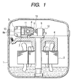
- Fig. 1 is a longitudinal sectional view showing an example the assembly structure of a closed compressor of this invention.
- Inside the closed housing 1 are installed an electric motor 2 and a compressor mechanism section 3.
- a frame 4 supports the electric motor 2 and the compressor mechanism section 3 inside of the closed housing 1.
- a shaft 5 with a rotor of the electric motor 2 fixed thereon is supported on the frame 4.
- On the upper end of the shaft 5 is mounted a crankshaft 6.
- a ball joint section 13 for joining between the crankshaft 6 and the piston 8 is comprised of a ball seat 8a of the piston 8 and a ball 11 of a connecting rod 9.
- the connecting rod 9 includes a rod portion 10, the ball 11 fixedly joined to one end of the rod portion 10, and a ring 12 which is fixedly mounted on the other end of the rod portion 10 and slides on the crankshaft 6.
- the electric motor 2 and the compressor mechanism section 3 are housed in the closed housing 1.
- the compressor mechanism section 3 is disposed on the upper end of the shaft 5 which is axially supported by the frame 4.
- the compressor mechanism section 3 is comprised of the eccentrically rotating crankshaft 6, the piston 8 reciprocally slided in the cylinder 7, and the connecting rod 9 including the ring 12 connected to the crankshaft 6 and the ball 11 connected to the piston 8 which are fixedly connected to the rod portion 10 into one unit.
- the connecting rod 9 and the piston 8, as shown in Fig. 1, are connected by the ball joint section 13 which is an assembly of the ball 11 and the ball seat 8a of the piston 8.
- Fig. 2 is a longitudinal sectional view showing an example of the shape of the piston 8 according to this invention.
- Fig. 3 is a side view seen from the direction of arrow of Fig. 2.
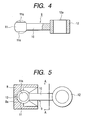
- Fig. 4 is a longitudinal sectional view showing an example of the shape of configuration of the connecting rod 9 including three members.
- the piston 8 is provided with the ball seat 8a in which the ball 11 of the connecting rod 9 is placed.
- the piston 8 is also provided with a hole 8c extending in a shape of funnel toward the piston end face side from the opening section 8b (Fig. 3) which is freely made smaller in diameter than the inside diameter of the ball seat 8a.
- the insertion groove 8d is an insertion port through which the ball 11 is inserted, and is formed symmetrically to the centerline Y-Y of the piston 8, with the bottom 8e extending to a position on an extension from the center of the ball diameter of the ball seat 8a.
- the connecting rod 9 is of such a configuration that the ball 11 is joined on one end of the rod portion 10 and the ring 12 on the other end by welding or other.
- the ball 11 has flat cut portion 11a, which is provided by removing the upper and lower portions of the ball indicated by broken lines.
- the flat cut portion 11a is formed in parallel with the end faces 12a of the ring 12, that is, in parallel with the upper and lower surfaces.
- the flat cut portion 11a may not necessarily be parallel, but is desired to be formed in parallel from the viewpoint of the shape of the opening section 8b of the piston 8 and the strength of the ball joint section 13 as described later.
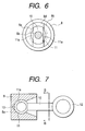
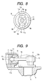
- Figs. 5, 6, 7 and 8 show the method of assembling the piston 8, the connecting rod 9 and the ball joint section 13.
- Fig. 5 is a longitudinal sectional view indicating the ball joint section 13 with the connecting rod 9 inserted into the piston 8 and also with the ring 12 tilted about 90 degrees to the direction in which the ring 12 is actually used in the closed compressor(with the ring 12 vertically tilted).
- Fig. 6 is a sectional view taken along line A-A of Fig. 5.
- Fig. 7 is a transverse sectional view of the cylinder 7 and the connecting rod 9 in Fig. 1.
- Fig. 8 is a sectional view taken along line B-B of Fig. 7. There is formed a space 14 between the insertion groove 8d of the piston 8 and the flat cut portion 11a of the ball 11, exposing a part of the ball seat 8a therethrough.
- the lubricating oil drawn up from an oil reservoir passes through the shaft 5 and a hole provided in the crankshaft, being squirted from the forward end of the crankshaft 6.
- the lubricating oil thus squirted partly flows along the rod portion 10 of the connecting rod 9 toward the inside of the piston 8.
- the lubricating oil that has entered the piston 8 flows along the hole 8c of the piston 8 into the space 14 formed by the insertion groove 8d and the flat cut portion 11a of the ball 11.
- the ball seat 8a is sufficiently lubricated with the lubricating oil squirted to a space which communicates with the space 14 formed by the ball seat 8a and the flat cut portion 11a.
- the insertion port of the piston 8 may be constituted also by inserting and fixing as large a block as the hole 8c which extends in a shape of funnel toward the end face of the piston, from the opening section 8b which is freely made smaller in diameter than the inside diameter of the ball seat 8a, or also by forming the insertion groove later.
- the piston 8 is freely rotatable in relation to the ball 11 during operation. With the operation of the compressor, a force acts on the piston 8, which rotates in relation to the connecting rod 9. If the insertion groove 8d of the piston 8 is aligned with the flat cut portion 11a of the ball 11 (the state shown in Fig. 5), the ball 11 will come out of the ball seat 8a. That is, the bail joint 13 is disconnected, resulting in a failure in proper compressor operation.
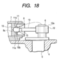
- Figs. 10 to 18 show a structure for restricting the relative rotation of the ball 11 and the piston 8, which will hereinafter be explained in detail.
- Figs. 10, 11 sectional view taken along line C-C of Fig. 10
- Fig. 12 perspective view seen from a stopper 15 described later
- Fig. 10 is a longitudinal sectional view of the crankshaft 6 with the stopper 15 installed on the structure that the connecting rod 9 is assembled to the piston 8.
- Fig. 12 shows one example of the stopper 15 formed of an elastic steel sheet.
- the stopper 15 has a flat portion 15a which is closely attached on the flat cut portion 11a of the ball 11, and is provided with a rising portion 15b on the forward end. On the opposite side of the rising portion 15b, a circular portion 15c having an opening of appropriate width continues to the flat portion 15a.
- the rising portion 15b is inserted, with an appropriate amount of clearance provided, into the space 14 formed by the insertion groove 8d of the piston 8 and the flat cut portion 11a of the ball 11.
- the circular portion 15c is placed in the stepped area 10a of the rod portion 10 (rolled around and crimped to the rod portion 10).
- the stopper 15 can be securely installed by firmly attaching the flat portion 15a to the flat cut portion 11a of the ball 11 and by crimping the circular portion 15c as stated above.
- the rotation of the piston 8 is restricted by interference of the rising portion 15b inserted into the space 14 and the insertion groove 8d.
- Figs. 13 and 14 (a sectional view taken along line D-D of Fig. 13), similarly to the stopper 15, show another example of the structure which restricts the rotation of the piston 8.
- Fig. 13 is a longitudinal sectional view showing the piston 8 installed in the cylinder 7.
- a spring pin 16 is pressed into a hole 8f formed by drilling in the surface of the ball seat 8a which communicates with the space 14.
- the spring pin 16 is designed to interfere with the ball 11 of the connecting rod 9 when the piston 8 turns, thereby restricting the rotation of the piston 8.
- Figs. 15, 16 (a sectional view taken along line E-E of Fig. 15), and 17 (a perspective view of the stopper 17) show one example of the stopper 17 produced of a piano wire.
- Fig. 15 is a transverse sectional view from the direction of the crankshaft, showing the structure of the piston 8 assembled with the connecting rod 9 and furthermore fitted with the stopper 17.
- Fig. 16 is a sectional view taken along line E-E of Fig. 15, the structure for installing the stopper 17 will be explained.
- a circular groove 8g in any arbitrary position in the slanting surface portion of the funnel-shaped hole 8c which is an opening of the piston 8 (the groove may be formed by cutting in the slanting surface).
- the circular portion 17a of the stopper 17 is fitted in the circular groove 8g.
- the stopper 17 has at least one circular portion 17a; in the embodiment disclosed in Fig. 17, the stopper has two circular portions 17a. A projection 17b is provided between these circular portions 17a. The width of the projection 17b is much the same as, or a little smaller than, that of the insertion groove 8d of the piston 8, that is, the width between the flat cut portions 11a of the ball 11.
- the projections 17b are set in the space 14 formed by the insertion groove 8d of the piston 8 and the flat cut portions 11a of the ball 11.
- the stopper 27 is fixed.
- the circular portion 17a of the stopper 17, as shown in Fig. 17, is formed expanded in relation to the projection 17b, thus being fitted with a spring force in the circular groove 8g.
- the lower space 14 is opened to feed the lubricating oil to the ball seat 8a.
Landscapes
- Engineering & Computer Science (AREA)
- Mechanical Engineering (AREA)
- General Engineering & Computer Science (AREA)
- Compressor (AREA)
- Pistons, Piston Rings, And Cylinders (AREA)
Applications Claiming Priority (2)
| Application Number | Priority Date | Filing Date | Title |
|---|---|---|---|
| JP2001386898 | 2001-12-20 | ||
| JP2001386898A JP4058266B2 (ja) | 2001-12-20 | 2001-12-20 | 密閉形圧縮機 |
Publications (3)
| Publication Number | Publication Date |
|---|---|
| EP1321673A2 true EP1321673A2 (fr) | 2003-06-25 |
| EP1321673A3 EP1321673A3 (fr) | 2003-11-26 |
| EP1321673B1 EP1321673B1 (fr) | 2007-05-09 |
Family
ID=19188006
Family Applications (1)
| Application Number | Title | Priority Date | Filing Date |
|---|---|---|---|
| EP02024842A Expired - Lifetime EP1321673B1 (fr) | 2001-12-20 | 2002-11-07 | Liaison piston-bielle |
Country Status (6)
| Country | Link |
|---|---|
| US (1) | US6718864B2 (fr) |
| EP (1) | EP1321673B1 (fr) |
| JP (1) | JP4058266B2 (fr) |
| KR (1) | KR100502382B1 (fr) |
| CN (1) | CN1232727C (fr) |
| ES (1) | ES2286189T3 (fr) |
Cited By (2)
| Publication number | Priority date | Publication date | Assignee | Title |
|---|---|---|---|---|
| WO2011001017A1 (fr) * | 2009-06-29 | 2011-01-06 | Wärtsilä Finland Oy | Procédé d'installation et de tourillonnement rotatif d'une tige de liaison sur un piston |
| CN107660826A (zh) * | 2016-07-27 | 2018-02-06 | 谢泽淦 | 双阀置空口罩 |
Families Citing this family (14)
| Publication number | Priority date | Publication date | Assignee | Title |
|---|---|---|---|---|
| DE10356200B4 (de) * | 2003-12-02 | 2006-08-03 | Man B & W Diesel Ag | Triebwerk einer Brennkraftmaschine mit Kolben und Pleuelstange |
| JP4512193B2 (ja) * | 2005-03-07 | 2010-07-28 | 日立アプライアンス株式会社 | レシプロ式密閉型圧縮機及びそれを用いた冷蔵・冷凍装置 |
| KR100724669B1 (ko) * | 2005-03-07 | 2007-06-07 | 히타치 홈 앤드 라이프 솔루션즈 가부시키가이샤 | 밀폐형 압축기 및 그 제조 방법 및 냉장ㆍ냉동 장치 |
| JP4834395B2 (ja) * | 2005-08-03 | 2011-12-14 | 日立アプライアンス株式会社 | 密閉形圧縮機 |
| CN101397987B (zh) * | 2005-08-03 | 2011-08-03 | 日立空调·家用电器株式会社 | 密封式压缩机 |
| CN200985869Y (zh) * | 2005-09-08 | 2007-12-05 | 松下电器产业株式会社 | 制冷剂压缩机 |
| JP4694956B2 (ja) * | 2005-12-07 | 2011-06-08 | 日立アプライアンス株式会社 | 密閉形圧縮機 |
| JP4300219B2 (ja) * | 2006-03-10 | 2009-07-22 | 日立アプライアンス株式会社 | 密閉型圧縮機及びこれを用いた冷蔵庫 |
| BRPI0603568A (pt) * | 2006-08-16 | 2008-04-08 | Whirlpool Sa | arranjo de montagem de pistão e haste de acionamento para compressor alternativo |
| US7497638B2 (en) * | 2006-11-09 | 2009-03-03 | The Boeing Company | Socket joint for tie-rod attachment system and method |
| JP4778995B2 (ja) * | 2008-09-03 | 2011-09-21 | 日立アプライアンス株式会社 | 密閉形圧縮機 |
| JP5086950B2 (ja) * | 2008-09-11 | 2012-11-28 | 本田技研工業株式会社 | ピストンとコンロッドとの球面連結構造 |
| JP4832502B2 (ja) * | 2008-12-15 | 2011-12-07 | 日立アプライアンス株式会社 | 密閉形圧縮機及び密閉形圧縮機を用いた冷蔵庫 |
| CN105221388A (zh) * | 2014-07-01 | 2016-01-06 | 安徽美芝制冷设备有限公司 | 具有外转子式电机的压缩机 |
Citations (1)
| Publication number | Priority date | Publication date | Assignee | Title |
|---|---|---|---|---|
| JPH0236794B2 (fr) | 1982-08-31 | 1990-08-20 | Tokyo Shibaura Electric Co |
Family Cites Families (15)
| Publication number | Priority date | Publication date | Assignee | Title |
|---|---|---|---|---|
| BE409023A (fr) | 1934-04-26 | |||
| GB1145140A (en) * | 1966-12-13 | 1969-03-12 | Danfoss As | Piston assemblies |
| SE372803B (fr) | 1972-12-22 | 1975-01-13 | Volvo Flygmotor Ab | |
| JPS53106906A (en) | 1977-03-02 | 1978-09-18 | Hitachi Ltd | Compressor |
| DE2829676A1 (de) | 1978-07-06 | 1980-01-24 | Gmt Medizinische Technik Gmbh | Endoprothese |
| JPS57132854U (fr) * | 1981-02-13 | 1982-08-19 | ||
| JPS60125784A (ja) * | 1983-12-08 | 1985-07-05 | Matsushita Refrig Co | 密閉型圧縮機のピストン・コンロッド結合装置 |
| JPH01124389U (fr) * | 1988-02-18 | 1989-08-24 | ||
| JPH01301964A (ja) * | 1988-05-31 | 1989-12-06 | Hitachi Ltd | ボールジョイントピストン |
| JPH02161180A (ja) * | 1988-12-14 | 1990-06-21 | Hitachi Ltd | ボールジョイントピストン |
| US5114261A (en) | 1989-07-31 | 1992-05-19 | Honda Giken Kogyo Kabushiki Kaisha | Swashplate type hydraulic device having a ball joint connection |
| US5048993A (en) * | 1989-12-30 | 1991-09-17 | Samsung Electronics Co., Ltd. | Ball joint assembly |
| US5118263A (en) * | 1990-04-27 | 1992-06-02 | Fritchman Jack F | Hermetic refrigeration compressor |
| KR100355956B1 (ko) * | 1998-11-27 | 2002-12-26 | 삼성광주전자 주식회사 | 자동조심기능을갖는볼조인트방식의피스톤조립체 |
| KR100350802B1 (ko) * | 1999-06-25 | 2002-09-09 | 삼성광주전자 주식회사 | 밀폐형 압축기 |
-
2001
- 2001-12-20 JP JP2001386898A patent/JP4058266B2/ja not_active Expired - Lifetime
-
2002
- 2002-10-28 US US10/281,158 patent/US6718864B2/en not_active Expired - Fee Related
- 2002-11-07 EP EP02024842A patent/EP1321673B1/fr not_active Expired - Lifetime
- 2002-11-07 ES ES02024842T patent/ES2286189T3/es not_active Expired - Lifetime
- 2002-11-19 CN CNB021514275A patent/CN1232727C/zh not_active Expired - Fee Related
- 2002-11-19 KR KR10-2002-0071823A patent/KR100502382B1/ko not_active Expired - Fee Related
Patent Citations (1)
| Publication number | Priority date | Publication date | Assignee | Title |
|---|---|---|---|---|
| JPH0236794B2 (fr) | 1982-08-31 | 1990-08-20 | Tokyo Shibaura Electric Co |
Cited By (2)
| Publication number | Priority date | Publication date | Assignee | Title |
|---|---|---|---|---|
| WO2011001017A1 (fr) * | 2009-06-29 | 2011-01-06 | Wärtsilä Finland Oy | Procédé d'installation et de tourillonnement rotatif d'une tige de liaison sur un piston |
| CN107660826A (zh) * | 2016-07-27 | 2018-02-06 | 谢泽淦 | 双阀置空口罩 |
Also Published As
| Publication number | Publication date |
|---|---|
| JP2003184751A (ja) | 2003-07-03 |
| CN1427152A (zh) | 2003-07-02 |
| EP1321673B1 (fr) | 2007-05-09 |
| EP1321673A3 (fr) | 2003-11-26 |
| JP4058266B2 (ja) | 2008-03-05 |
| US20030116013A1 (en) | 2003-06-26 |
| ES2286189T3 (es) | 2007-12-01 |
| CN1232727C (zh) | 2005-12-21 |
| US6718864B2 (en) | 2004-04-13 |
| KR100502382B1 (ko) | 2005-07-19 |
| KR20030052972A (ko) | 2003-06-27 |
Similar Documents
| Publication | Publication Date | Title |
|---|---|---|
| US6718864B2 (en) | Closed compressor | |
| EP1232342B1 (fr) | Ensemble compresseur | |
| US6254365B1 (en) | Compressor | |
| JP3477474B2 (ja) | ボールジョイントの組立方法 | |
| JP6298087B2 (ja) | コネクティングロッドおよび内燃機関 | |
| CN105849443A (zh) | 具有通道的无销活塞 | |
| US6705203B2 (en) | Extended male slipper servo pad arrangement for positioning swashplate and method assembling same | |
| JP3410220B2 (ja) | 電動流量制御弁 | |
| JPH11257110A (ja) | 内燃機関の圧縮比切換装置 | |
| KR20050086356A (ko) | 가변용량 압축기 | |
| JP2004251410A (ja) | 軸継ぎ手 | |
| KR20010065249A (ko) | 밀폐형 압축기의 커넥팅로드 설치구조 및 그 방법 | |
| CN114076208B (zh) | 流量控制阀及冷冻循环系统 | |
| JP7405781B2 (ja) | 流量制御弁および冷凍サイクルシステム | |
| JP3886186B2 (ja) | 往復ピストン圧縮機 | |
| US20060140712A1 (en) | Gas spring ball joint and method for manufacturing the same | |
| JP2003049943A (ja) | ロッドの連結構造およびロッド連結用のかしめ具 | |
| JP2009097399A (ja) | スクロール圧縮機及びその製造方法 | |
| KR200184075Y1 (ko) | 밀폐형 압축기의 커넥팅로드 설치구조 | |
| KR200293348Y1 (ko) | 밀폐형 왕복동식 압축기 | |
| KR200224988Y1 (ko) | 밀폐형 압축기의 피스톤핀 설치구조 | |
| KR100780835B1 (ko) | 밀폐형 압축기의 프레임과 실린더 결합구조 | |
| JP4652125B2 (ja) | 密閉形圧縮機 | |
| US6401594B1 (en) | Connecting rod with integral grease reservoir | |
| KR20040020550A (ko) | 밀폐형 압축기의 프레임 |
Legal Events
| Date | Code | Title | Description |
|---|---|---|---|
| PUAI | Public reference made under article 153(3) epc to a published international application that has entered the european phase |
Free format text: ORIGINAL CODE: 0009012 |
|
| 17P | Request for examination filed |
Effective date: 20021107 |
|
| AK | Designated contracting states |
Designated state(s): AT BE BG CH CY CZ DE DK EE ES FI FR GB GR IE IT LI LU MC NL PT SE SK TR |
|
| AX | Request for extension of the european patent |
Extension state: AL LT LV MK RO SI |
|
| PUAL | Search report despatched |
Free format text: ORIGINAL CODE: 0009013 |
|
| AK | Designated contracting states |
Kind code of ref document: A3 Designated state(s): AT BE BG CH CY CZ DE DK EE ES FI FR GB GR IE IT LI LU MC NL PT SE SK TR |
|
| AX | Request for extension of the european patent |
Extension state: AL LT LV MK RO SI |
|
| 17Q | First examination report despatched |
Effective date: 20040426 |
|
| AKX | Designation fees paid |
Designated state(s): ES IT |
|
| REG | Reference to a national code |
Ref country code: DE Ref legal event code: 8566 |
|
| GRAP | Despatch of communication of intention to grant a patent |
Free format text: ORIGINAL CODE: EPIDOSNIGR1 |
|
| GRAS | Grant fee paid |
Free format text: ORIGINAL CODE: EPIDOSNIGR3 |
|
| GRAA | (expected) grant |
Free format text: ORIGINAL CODE: 0009210 |
|
| RAP1 | Party data changed (applicant data changed or rights of an application transferred) |
Owner name: HITACHI APPLIANCES, INC. |
|
| AK | Designated contracting states |
Kind code of ref document: B1 Designated state(s): ES IT |
|
| REG | Reference to a national code |
Ref country code: ES Ref legal event code: FG2A Ref document number: 2286189 Country of ref document: ES Kind code of ref document: T3 |
|
| PLBE | No opposition filed within time limit |
Free format text: ORIGINAL CODE: 0009261 |
|
| STAA | Information on the status of an ep patent application or granted ep patent |
Free format text: STATUS: NO OPPOSITION FILED WITHIN TIME LIMIT |
|
| 26N | No opposition filed |
Effective date: 20080212 |
|
| PGFP | Annual fee paid to national office [announced via postgrant information from national office to epo] |
Ref country code: IT Payment date: 20121113 Year of fee payment: 11 Ref country code: ES Payment date: 20121123 Year of fee payment: 11 |
|
| PG25 | Lapsed in a contracting state [announced via postgrant information from national office to epo] |
Ref country code: IT Free format text: LAPSE BECAUSE OF NON-PAYMENT OF DUE FEES Effective date: 20131107 |
|
| REG | Reference to a national code |
Ref country code: ES Ref legal event code: FD2A Effective date: 20150407 |
|
| PG25 | Lapsed in a contracting state [announced via postgrant information from national office to epo] |
Ref country code: ES Free format text: LAPSE BECAUSE OF NON-PAYMENT OF DUE FEES Effective date: 20131108 |