EP1321732A2 - Dispositif pour le séchage des ébauches - Google Patents
Dispositif pour le séchage des ébauches Download PDFInfo
- Publication number
- EP1321732A2 EP1321732A2 EP02027238A EP02027238A EP1321732A2 EP 1321732 A2 EP1321732 A2 EP 1321732A2 EP 02027238 A EP02027238 A EP 02027238A EP 02027238 A EP02027238 A EP 02027238A EP 1321732 A2 EP1321732 A2 EP 1321732A2
- Authority
- EP
- European Patent Office
- Prior art keywords
- blow
- openings
- moldings
- drying
- suction openings
- Prior art date
- Legal status (The legal status is an assumption and is not a legal conclusion. Google has not performed a legal analysis and makes no representation as to the accuracy of the status listed.)
- Withdrawn
Links
Images


Classifications
-
- B—PERFORMING OPERATIONS; TRANSPORTING
- B28—WORKING CEMENT, CLAY, OR STONE
- B28B—SHAPING CLAY OR OTHER CERAMIC COMPOSITIONS; SHAPING SLAG; SHAPING MIXTURES CONTAINING CEMENTITIOUS MATERIAL, e.g. PLASTER
- B28B11/00—Apparatus or processes for treating or working the shaped or preshaped articles
- B28B11/24—Apparatus or processes for treating or working the shaped or preshaped articles for curing, setting or hardening
- B28B11/243—Setting, e.g. drying, dehydrating or firing ceramic articles
-
- B—PERFORMING OPERATIONS; TRANSPORTING
- B28—WORKING CEMENT, CLAY, OR STONE
- B28B—SHAPING CLAY OR OTHER CERAMIC COMPOSITIONS; SHAPING SLAG; SHAPING MIXTURES CONTAINING CEMENTITIOUS MATERIAL, e.g. PLASTER
- B28B11/00—Apparatus or processes for treating or working the shaped or preshaped articles
- B28B11/24—Apparatus or processes for treating or working the shaped or preshaped articles for curing, setting or hardening
- B28B11/248—Supports for drying
-
- F—MECHANICAL ENGINEERING; LIGHTING; HEATING; WEAPONS; BLASTING
- F26—DRYING
- F26B—DRYING SOLID MATERIALS OR OBJECTS BY REMOVING LIQUID THEREFROM
- F26B21/00—Arrangements for supplying or controlling air or other gases for drying solid materials or objects
- F26B21/50—Ducting arrangements from the source of air or other gases to the materials or objects being dried
-
- F—MECHANICAL ENGINEERING; LIGHTING; HEATING; WEAPONS; BLASTING
- F26—DRYING
- F26B—DRYING SOLID MATERIALS OR OBJECTS BY REMOVING LIQUID THEREFROM
- F26B25/00—Details of general application not covered by group F26B21/00 or F26B23/00
- F26B25/06—Chambers, containers, or receptacles
- F26B25/14—Chambers, containers, receptacles of simple construction
- F26B25/18—Chambers, containers, receptacles of simple construction mainly open, e.g. dish, tray, pan, rack
-
- F—MECHANICAL ENGINEERING; LIGHTING; HEATING; WEAPONS; BLASTING
- F26—DRYING
- F26B—DRYING SOLID MATERIALS OR OBJECTS BY REMOVING LIQUID THEREFROM
- F26B2210/00—Drying processes and machines for solid objects characterised by the specific requirements of the drying goods
- F26B2210/02—Ceramic articles or ceramic semi-finished articles
Definitions
- the invention relates to a device for drying moldings, in particular Ceramic moldings, such as roof tiles or the like, according to the generic term of claim 1.
- Freshly pressed moldings are placed on so-called dry goods carriers during drying (TGT) supported, of which several are stacked and side by side can be held in the device.
- TGT dry goods carriers during drying
- the TGT often consist of supporting ones Frames, on which, for example, 8 frames are applied, whose support elements support the moldings.
- Ceramic moldings pressed and preferably moist from a ceramic mass can lie on the drying rack of the dry goods carrier be stored.
- the dry goods carriers are in dryer cars or racks used. In the form with one or more on top of and next to each other lying layers form the so-called pile stock. You can both inserted in the dryer box car levels and on platform cars be piled up.
- the drying frames are in a continuous or chamber dryer with the moldings with a drying gas, especially conditioned Drying air, washed around.
- the moldings are essentially on their surfaces Flows in parallel.
- a parallel flow creates in the area the molded surfaces slipstream and boundary layers, which only a low Ensure heat transfer and low evaporation and thus a unsatisfactory drying of the moldings.
- the undersides of the Moldings are also largely covered so that they dry more slowly than the tops of the moldings.
- the arrangement in the Pile trimmings sweep the air one after the other along several rows of moldings. It absorbs moisture and gives off heat, so that the later, rows of moldings exposed air to a different humidity and temperature flows along. Since the total drying time after the drying time for the the slowest drying molding is long drying times necessary.
- the dry goods carriers are known from DE 100 00 261 themselves to be provided with air supply ducts, which are connected to the facing each molded product and transverse to the plane of extension of the dry goods carrier Pointing blow-out openings apply drying air to the moldings.
- the outlet openings are distributed over the dry goods carrier.
- a suction of the drying gas takes place, for example, via vertical walls, that stand next to the molding and have suction openings instead.
- the invention is therefore based on the task of drying the individual To better take into account the geometry of the moldings and the above To avoid disadvantages.
- At least one suction opening is assigned to each discharge opening, can short flows can be set, which cover only a small area of the Touch moldings, such as an area that dries particularly slowly.
- the geometry of the respective molding can be individually optimized Drying can be achieved.
- the drying time can be very different Types of moldings can be lowered.
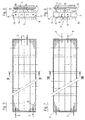
- a device designated overall by 1 is an example shown to dry various types of items, such as Moldings 2 made of ceramic, is used.
- the device is designed here as a platform car and includes - not necessarily - several levels 3 on which the moldings 2 can be arranged side by side.
- the device 1 is rollable and in a drying room 4, such as one Continuous or chamber dryer, inserted.
- a drying room 4 such as one Continuous or chamber dryer
- Each individual tier 3 comprises at least one dry goods carrier 5, which is in a substantially horizontal plane 7 and the base 6a, 6b, 6c, 6d, 6e, 6f supports moldings 2 resting on them.
- the moldings 2 can form a wide variety of shapes, such as roof tiles, etc. a. also verge bricks or other special shapes, up to large-scale products such as large ones Slabs or surfaces.
- the moldings 2 do not have to be made of ceramic be, but there are a wide variety of materials that a binding or Go through drying process into consideration.
- the dry goods carriers 5 each have one or more channels 8 for feeding of drying gas, here conditioned air, as well as one or more channels 9 to derive them.
- the feed channels 8 open into first blow-out openings 10 on the top 12 and second exhaust openings 11 on the bottom 13 the dry goods carrier 5. Due to the tiered arrangement of the dry goods carriers 5, the blow-out openings 10 are at least one resting and the Blow-out openings 11 at least one lying under the dry goods carrier 5 Form 2 facing.
- One end of the channels 8, 9 is in each case with bulkhead plates 8a, 9a closed.
- first and second suction openings on the top 12 and on the bottom 13 14, 15 are provided, each in a discharge channel 9 of the Open dry goods carrier 5.
- both the arrangements of Blow-out and suction openings 10, 11, 14, 15 and the associated feed openings and discharge channels 8, 9 vary.
- the feed and discharge channels 8, 9 in the extension plane 7 of the dry goods carrier 5 alternating with each other, which is not mandatory. Also is for example an arrangement of the feed and discharge channels 8, 9 one above the other is possible. In any case, feed and discharge channels 8, 9 are located such that Drying gas flows 16 within the area of a dry goods carrier 5 can take place.
- drying gas flows 16 which also define the moldings 2 Apply air.
- drying gas flow 16 is not just a selective impact of the air, but it can also result in tangential flow areas that are linear or flat flow along the molding 2 and thus define critical areas can expose to an increased degree of drying.
- blow-out and suction openings 10, 11, 14, 15 each are formed only as holes in the surface, but the openings 10, 11, 14, 15 can also run as channels with an oblique direction, whereby the air already exits the surface of the dry goods carrier 5 Component tangent to molding 2 can receive.
- Intake openings 14, 15 possible, the oblique position of blow-out and intake openings 10, 14 or 11, 15 can each be coordinated, for example in that the inclinations face each other. This can almost any flow optimization for different areas of a Moldings 2 are formed.
- blow-out and suction openings 10, 11, 14, 15 are advantageous in their arrangement adapted to the respective molding 2, so regularly not in uniform Spaces arranged side by side.
- the invention is adaptable to different moldings 2 and overall for Various drying devices and drying chambers can be used.
Landscapes
- Engineering & Computer Science (AREA)
- Mechanical Engineering (AREA)
- Ceramic Engineering (AREA)
- General Engineering & Computer Science (AREA)
- Structural Engineering (AREA)
- Chemical & Material Sciences (AREA)
- Drying Of Solid Materials (AREA)
- Devices For Post-Treatments, Processing, Supply, Discharge, And Other Processes (AREA)
Applications Claiming Priority (2)
| Application Number | Priority Date | Filing Date | Title |
|---|---|---|---|
| DE10163129 | 2001-12-20 | ||
| DE10163129A DE10163129C1 (de) | 2001-12-20 | 2001-12-20 | Vorrichtung zum Trocknen von Formlingen |
Publications (1)
| Publication Number | Publication Date |
|---|---|
| EP1321732A2 true EP1321732A2 (fr) | 2003-06-25 |
Family
ID=7710280
Family Applications (1)
| Application Number | Title | Priority Date | Filing Date |
|---|---|---|---|
| EP02027238A Withdrawn EP1321732A2 (fr) | 2001-12-20 | 2002-12-06 | Dispositif pour le séchage des ébauches |
Country Status (2)
| Country | Link |
|---|---|
| EP (1) | EP1321732A2 (fr) |
| DE (1) | DE10163129C1 (fr) |
Cited By (1)
| Publication number | Priority date | Publication date | Assignee | Title |
|---|---|---|---|---|
| EP2065664A3 (fr) * | 2007-11-27 | 2012-11-07 | Robert Thomas Metall- und Elektrowerke GmbH & Co. KG | Séchoir pour ébauches de céramique perforées |
Families Citing this family (5)
| Publication number | Priority date | Publication date | Assignee | Title |
|---|---|---|---|---|
| DE102005037881A1 (de) * | 2005-08-10 | 2007-02-22 | Hans Lingl Anlagenbau Und Verfahrenstechnik Gmbh & Co. Kg | Vorrichtung zum Trocknen von Formlingen, mit an der Einfahrseite für einen Trocknungswagen zugänglichen Trocknungskammern |
| FR2890728B1 (fr) * | 2005-09-14 | 2007-11-02 | Terreal Sa | Dispositif de support pour le sechage de produits en terre crue |
| DE102006050625B4 (de) * | 2006-10-26 | 2008-07-10 | Maschinen- Und Stahlbau Julius Lippert Gmbh & Co. Kg | Anlage zum Trocknen mindestens einer mehrteiligen Gießform |
| ITMO20070127A1 (it) * | 2007-04-06 | 2008-10-07 | Ancora Spa | Apparato per asciugare piastrelle |
| IT1393966B1 (it) * | 2009-03-26 | 2012-05-17 | Gerardi | Essicatoio per manufatti, particolarmente ceramiche, laterizi, resine, cementi, pietre naturali e simili |
Citations (1)
| Publication number | Priority date | Publication date | Assignee | Title |
|---|---|---|---|---|
| DE10000261A1 (de) | 2000-01-06 | 2001-07-19 | Thomas Robert Metall Elektro | Trockner für plattenförmige Keramikformlinge |
-
2001
- 2001-12-20 DE DE10163129A patent/DE10163129C1/de not_active Expired - Fee Related
-
2002
- 2002-12-06 EP EP02027238A patent/EP1321732A2/fr not_active Withdrawn
Patent Citations (1)
| Publication number | Priority date | Publication date | Assignee | Title |
|---|---|---|---|---|
| DE10000261A1 (de) | 2000-01-06 | 2001-07-19 | Thomas Robert Metall Elektro | Trockner für plattenförmige Keramikformlinge |
Cited By (1)
| Publication number | Priority date | Publication date | Assignee | Title |
|---|---|---|---|---|
| EP2065664A3 (fr) * | 2007-11-27 | 2012-11-07 | Robert Thomas Metall- und Elektrowerke GmbH & Co. KG | Séchoir pour ébauches de céramique perforées |
Also Published As
| Publication number | Publication date |
|---|---|
| DE10163129C1 (de) | 2002-10-24 |
Similar Documents
| Publication | Publication Date | Title |
|---|---|---|
| DE3030604A1 (de) | Windtrocknungsvorrichtung | |
| DE202015106039U1 (de) | Behandlungseinrichtung | |
| DE2744449C2 (de) | Vorrichtung zur Steuerung der Strömung von körnigem Gut durch einen Trocknungsturm | |
| EP0707530B1 (fr) | Procede et installation pour le sechage et/ou la cuisson de briques vertes | |
| EP1114972B1 (fr) | Sécheur pour corps céramiques sous forme de plaques | |
| DE19606892C2 (de) | Flachbandverfahren zur Trocknung von Plättchen | |
| DE2934022C2 (fr) | ||
| EP1321732A2 (fr) | Dispositif pour le séchage des ébauches | |
| DE2918833C2 (de) | Vorrichtung zum Trocknen und Krumpfen von textiler Maschenware | |
| EP0751360B1 (fr) | Procédé de séchage de briques creuses, et tunnel de séchage pour la mise en oeuvre de ce procédé | |
| WO1997005437A1 (fr) | Procede et dispositif de sechage de briques crues ceramique | |
| DE4412352A1 (de) | Verfahren und Tunneltrockner zum Trocknen keramischer Formlinge | |
| DE3545498A1 (de) | Verfahren und vorrichtung zur herstellung keramischer massenprodukte | |
| DE19727937C2 (de) | Tunneltrockner-Anlage zum Trocknen von Ziegeln, insbesondere Lochziegeln | |
| EP2065664A2 (fr) | Séchoir pour ébauches de céramique perforées | |
| AT405878B (de) | Verfahren zum trocknen von formlingen aus keramischem material, insbesondere von ziegeln, sowie anlage zur durchführung des verfahrens | |
| EP0828125A2 (fr) | Procédé et tunnel de séchage pour sécher des ébauches à bloc creux | |
| DE1604774C (de) | Vorrichtung zum Trocknen von kerami sehen Gegenstanden mittels Warmluft | |
| EP0754285B1 (fr) | Procede et dispositif permettant de secher des briques perforees ou des articles similaires | |
| EP0489369B1 (fr) | Plaque de grille | |
| DE4412353C2 (de) | Tunneltrockner zum Trocknen keramischer Formlinge | |
| DE2033355C3 (de) | Tunneltrockner, insbesondere zum WeiBtrocknen von geformten Rohlingen sanitärer Gegenstände aus keramischem Material, wie Klosett-, Waschbecken u.dgl | |
| DE29813535U1 (de) | Tunneltrockner-Anlage zum Trocknen von Dachziegel-Formlingen | |
| DE1604774B (de) | Vorrichtung zum Trocknen von keramischen Gegenständen mittels Warmluft | |
| EP0877220A2 (fr) | Dispositif et procédé de séchage de corps céramiques moulés |
Legal Events
| Date | Code | Title | Description |
|---|---|---|---|
| PUAI | Public reference made under article 153(3) epc to a published international application that has entered the european phase |
Free format text: ORIGINAL CODE: 0009012 |
|
| AK | Designated contracting states |
Designated state(s): AT BE BG CH CY CZ DE DK EE ES FI FR GB GR IE IT LI LU MC NL PT SE SI SK TR |
|
| AX | Request for extension of the european patent |
Extension state: AL LT LV MK RO |
|
| STAA | Information on the status of an ep patent application or granted ep patent |
Free format text: STATUS: THE APPLICATION HAS BEEN WITHDRAWN |
|
| 18W | Application withdrawn |
Effective date: 20041028 |