EP1321960A2 - Tube cathodique couleur de type plat - Google Patents
Tube cathodique couleur de type plat Download PDFInfo
- Publication number
- EP1321960A2 EP1321960A2 EP02254615A EP02254615A EP1321960A2 EP 1321960 A2 EP1321960 A2 EP 1321960A2 EP 02254615 A EP02254615 A EP 02254615A EP 02254615 A EP02254615 A EP 02254615A EP 1321960 A2 EP1321960 A2 EP 1321960A2
- Authority
- EP
- European Patent Office
- Prior art keywords
- panel
- ray tube
- cathode ray
- color cathode
- type color
- Prior art date
- Legal status (The legal status is an assumption and is not a legal conclusion. Google has not performed a legal analysis and makes no representation as to the accuracy of the status listed.)
- Withdrawn
Links
Images


Classifications
-
- H—ELECTRICITY
- H01—ELECTRIC ELEMENTS
- H01J—ELECTRIC DISCHARGE TUBES OR DISCHARGE LAMPS
- H01J29/00—Details of cathode-ray tubes or of electron-beam tubes of the types covered by group H01J31/00
- H01J29/02—Electrodes; Screens; Mounting, supporting, spacing or insulating thereof
-
- H—ELECTRICITY
- H01—ELECTRIC ELEMENTS
- H01J—ELECTRIC DISCHARGE TUBES OR DISCHARGE LAMPS
- H01J29/00—Details of cathode-ray tubes or of electron-beam tubes of the types covered by group H01J31/00
- H01J29/86—Vessels; Containers; Vacuum locks
-
- H—ELECTRICITY
- H01—ELECTRIC ELEMENTS
- H01J—ELECTRIC DISCHARGE TUBES OR DISCHARGE LAMPS
- H01J2229/00—Details of cathode ray tubes or electron beam tubes
- H01J2229/86—Vessels and containers
- H01J2229/8613—Faceplates
- H01J2229/8616—Faceplates characterised by shape
-
- H—ELECTRICITY
- H01—ELECTRIC ELEMENTS
- H01J—ELECTRIC DISCHARGE TUBES OR DISCHARGE LAMPS
- H01J2229/00—Details of cathode ray tubes or electron beam tubes
- H01J2229/86—Vessels and containers
- H01J2229/8613—Faceplates
- H01J2229/8616—Faceplates characterised by shape
- H01J2229/862—Parameterised shape, e.g. expression, relationship or equation
Definitions
- the present invention relates to a flat type color cathode ray tube, and more particularly, the present invention relates to a flat type color cathode ray tube of high quality, which is capable of guaranteeing brightness uniformity while improving contrast, thereby ensuring flatness and visual distinction of an image.
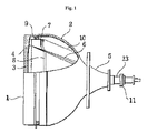
- the color cathode ray tube includes a panel 1 defining a front surface of the cathode ray tube, a shadow mask 3 performing a function of selecting colors of emitted electron beams 11 in the panel 1, a frame 4 for fastening and supporting the shadow mask 3, a stud pin 6 for securing the frame 4 to the panel 1, a spring 5 for connecting the stud pin 6 and the frame 4 with each other, a funnel 2 coupled to a rear end of the panel 1 to maintain the inside of the panel 1 under a vacuum pressure, a tubular neck section 10 extending rearward from a rear end of the funnel 2, an electron gun 8 mounted in the neck section 10 to emit electron beams 11, an inner shield 17 assembled to the frame 4 to protect the emitted electron beams 11 from an external magnetic field, a deflection yoke 9 surrounding a circumferential outer surface of the funnel 2 to deflect the
- Curvatures of inner and outer surfaces of the panel 1 influence an implosion-resistant characteristic and visual distinction of an image displayed on the panel 1.
- a curvature of the inner surface of the panel 1 significantly affects flatness and distortion of an image, to thereby influence the visual distinction.
- the curvature of the inner surface of the panel 1 affects a transmittance of the panel 1 and transmittance formation, so as to ensure brightness uniformity and allow light and dark regions on a picture image to be easily distinguished. That is to say, a precise inner surface curvature of the panel 1 plays an important role in realizing a cathode ray tube of high quality.
- the electron beams 11 emitted from the electron gun 8 are deflected by the deflection yoke 9 and then pass through apertures defined in the shadow mask 3, in a manner such that they are impinged onto fluorescent materials applied on the inner surface of the panel 1 and respectively aligned with the apertures of the shadow mask 3, to display a picture image.
- a contour of the picture image is determined by the inner and outer surfaces of the panel 1.
- a contour of the picture image is changed by refraction of light, and the resultantly displayed picture image has a curved contour depending on the curvatures of the inner and outer surfaces.
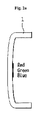
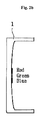
- FIG. 2a is a side cross-sectional view independently illustrating a contour of a curved panel which has curvatures on both inner and outer surfaces thereof; and FIG. 2b is a side cross-sectional view independently illustrating a contour of a flat panel which has a curvature only on an inner surface thereof.
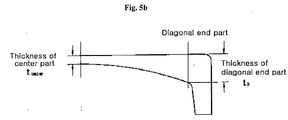
- An inner surface curvature of a panel can be expressed by a "wedge rate" which is a thickness ratio between a center part and a diagonal end part of the panel.
- the conventional flat panel having a curvature only on an inner surface thereof possesses a wedge rate of no less than 200%.
- the conventional flat panel tends to be overly increased in its thickness at a peripheral part thereof, especially at the diagonal end part. Consequently, as a difference between transmittances of the center part and the peripheral part is increased, when a picture image is created on the panel, a remarkable difference exists between brightnesses of the center and peripheral parts, so that eye strain is caused.
- the conventional cathode ray tube has a wedge rate of 200%, which is calculated as a thickness ratio between the center part and the diagonal end part of the panel, a transmittance is decreased at the peripheral part, and thereby, brightness uniformity of the picture image cannot be guaranteed.
- the present invention has been made in an effort to address the problems occurring in the related art.
- a flat type color cathode ray tube comprising: a rectangular panel having an outer surface which is substantially flat and an inner surface which takes a predetermined curvature, the rectangular panel being formed with a skirt part which extends substantially perpendicularly to the inner and outer surfaces; a shadow mask for performing a function of selecting colors of emitted electron beams in the panel; a frame for applying tensioning force to the shadow mask and supporting the shadow mask; a funnel coupled to a rear end of the panel to maintain the inside of the panel under a vacuum pressure; a tubular neck section extending rearward from a rear end of the funnel; an electron gun mounted in the neck section to emit electron beams; and a deflection yoke surrounding a circumferential outer surface of the funnel to deflect electron beams; wherein the panel possesses at a center part thereof a transmittance of 45% ⁇ 75%, and the inner surface of the panel possesses an on-diagonal-axis
- a flat type color cathode ray tube comprising: a panel having an outer surface which is substantially flat and an inner surface which takes a predetermined curvature, the inner surface of the panel possessing an on-major-axis curvature R X , an on-minor-axis curvature R Y and an on-diagonal-axis curvature R D which respectively satisfy correlations, 4.5R XO ⁇ R X ⁇ 8.0R XO , 2.5R YO ⁇ R Y ⁇ 8.0R YO and 3.5R DO ⁇ R D ⁇ 8.0R DO .
- a flat type color cathode ray tube comprising: a panel having an outer surface which is substantially flat and an inner surface which takes a predetermined curvature, the panel possessing at a center part thereof a transmittance of 45% ⁇ 75%, the panel further possessing a wedge rate as a thickness ratio between the center part and a diagonal end part of the panel, which satisfies a correlation, 1.4 ⁇ wedge rate ⁇ 2.0.
- a conventional flat panel having a curvature only on an inner surface thereof possesses a substantial wedge rate of no less than 200%, which wedge rate is a thickness ratio between a center part and a diagonal end part of the panel.
- wedge rate is a thickness ratio between a center part and a diagonal end part of the panel.
- the panel having a high transmittance while it is possible to increase a brightness at a center part of a picture image, a distinguishability between lightness and darkness, that is, contrast which is a brightness ratio of the lightest to the darkest parts of the picture image when an illumination of an external light source is 200 lux, is deteriorated.
- contrast which is a brightness ratio of the lightest to the darkest parts of the picture image when an illumination of an external light source is 200 lux
- a representative radius of curvature R D along a diagonal axis and on the inner surface of the panel is designed to satisfy the following inequality (1): 3.5R ⁇ R D ⁇ 8.0R where R is a product of 1.767 and a diagonal length of an effective surface along the diagonal axis.
- an image floating phenomenon in which an image is floated in conformity with a refractive index and a thickness of the panel may occur in the picture image which is produced when electron beams are impinged onto fluorescent materials applied to the inner surface of the panel.
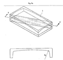
- this image floating phenomenon as can be readily seen from FIG. 3d, if a representative radius of curvature R D along the diagonal axis and on the inner surface of the panel is no less than 8R, by a floated amount I D of the diagonal end part of the panel, a concave picture image curved in a reverse direction is produced.
- a representative radius of curvature R D along the diagonal axis and on the inner surface of the panel is no greater than 4R, since an image floating effect of the peripheral part is insufficient when compared to that of the center part, degradation of flatness of the picture image is caused.
- a representative radius of curvature R D along the diagonal axis and on the inner surface of the panel is designed to satisfy the following inequality (2): 4.0R ⁇ R D ⁇ 5.0R
- an on-diagonal-axis curvature is regarded as a most important factor for determining an entire inner surface curvature.
- an on-major-axis curvature and an on-minor-axis curvature must be established to define a contour substantially coinciding to that defined by the on-diagonal-axis curvature, thereby to prevent a picture image from being distorted.
- an on-major-axis curvature R X in order to improve image quality and prevent flatness of a picture image from being degraded, an on-major-axis curvature R X , an on-minor-axis curvature R Y and an on-diagonal-axis curvature R D must respectively satisfy the following inequalities (3), (4) and (5): 4.5R XO ⁇ R X ⁇ 8.0R XO 2.5R YO ⁇ R Y ⁇ 8.0R YO 3.5R DO ⁇ R D ⁇ 8.0R DO where R XO , R YO and R DO are products of 1.767 and on-major-axis, on-minor-axis and on-diagonal-axis lengths, respectively, of an effective surface of the panel.
- an on-major-axis curvature R X in order to augment a strength and a howling characteristic of the shadow mask, which are influenced by the inner surface curvature of the panel, while improving flatness of the picture image, it is preferred that an on-major-axis curvature R X , an on-minor-axis curvature R Y and an on-diagonal-axis curvature R D respectively satisfy the following inequalities (6), (7) and (8): 5.0R XO ⁇ R X ⁇ 7.0R XO 2.5R YO ⁇ R Y ⁇ 3.5R YO 4.0R DO ⁇ R D ⁇ 5.0R DO
- Another one of important factors of a flat type cathode ray tube is brightness uniformity of the picture image.
- brightness uniformity of a picture image which provides viewing comfort, is considered as appropriate when a rate between a brightness of the diagonal end part and a brightness of the center part is no less than 50%.
- the conventional panel for a cathode ray tube which has at the center part thereof a high transmittance of no less than 85%, while it is possible to secure brightness uniformity of no less than 50% because a thickness is increased at the diagonal end part of the panel, a distinguishability between lightness and darkness is deteriorated.
- a rate of a transmittance at the diagonal end part of the panel with respect to a transmittance at the center part of the panel is maintained within a range of no greater than 80%.
- a thickness must be decreased at the peripheral part of the panel.
- a transmittance ratio between the center part and the diagonal end part of the panel exceeds 80%, as a thickness is increased at the diagonal end part, a radius of curvature of the inner surface is increased.
- a strength of the shadow mask, for withstanding external vibration is diminished.
- quality of the cathode ray tube cannot but be degraded.
- a transmittance ratio between the center part and the diagonal end part of the panel is maintained within a range of no greater than 80%.
- a wedge rate which is a thickness ratio between the center part and the diagonal end part of the panel, can satisfy the following inequality (9):
- the more a thickness ratio between the center part and the diagonal end part of the panel is increased the more a thermal stress is excessively induced, due to a corresponding thickness difference, in a thermal process through which the panel passes, whereby a defective proportion is increased upon manufacture of panels.
- a wedge rate as a thickness ratio between the center part and the diagonal end part of the panel is no greater than 1.4, as a radius of curvature of the shadow mask is increased depending upon an inner surface curvature of the panel, a strength and a howling characteristic of the shadow mask are diminished.
- a thickness of the center part of the panel is related with an implosion-resistant characteristic and safety of the finally-produced cathode ray tube. If a thickness of the center part of the panel is less than 12 mm, while a transmittance at the diagonal end part of the panel can be increased under the same wedge rate to improve brightness uniformity of the picture image, as an implosion-resistant characteristic is degraded, the likelihood of a cathode ray tube to implode upon impact test is increased, and thereby, a safety-related issue is raised.
- a thickness of the center part of the panel is greater than 15 mm in consideration of safety, while impact resistance is ameliorated to improve an implosion-resistant characteristic, nevertheless, as can be readily seen from FIG. 2, since a transmittance of the peripheral part has a low value and a transmittance ratio between the center part and the diagonal end part of the panel is decreased, it is difficult to properly maintain brightness uniformity over the picture image.
- the flat type color cathode ray tube according to the present invention including a panel which has a flat outer surface and a curved inner surface, provides advantages in that, since a transmittance of a center part of the panel is maintained within a range of 45 ⁇ 75%, a distinguishability between lightness and darkness (contrast) as one of major characteristics determining image quality is improved.
- contrast and brightness uniformity can be complementarily improved while not incurring additional processes and manufacturing costs, whereby it is possible to enhance flatness and visual distinction of a resultant picture image.
Landscapes
- Vessels, Lead-In Wires, Accessory Apparatuses For Cathode-Ray Tubes (AREA)
Applications Claiming Priority (2)
| Application Number | Priority Date | Filing Date | Title |
|---|---|---|---|
| KR2001081418 | 2001-12-19 | ||
| KR10-2001-0081418A KR100439268B1 (ko) | 2001-12-19 | 2001-12-19 | 평면형 컬러음극선관 |
Publications (2)
| Publication Number | Publication Date |
|---|---|
| EP1321960A2 true EP1321960A2 (fr) | 2003-06-25 |
| EP1321960A3 EP1321960A3 (fr) | 2004-07-14 |
Family
ID=19717264
Family Applications (1)
| Application Number | Title | Priority Date | Filing Date |
|---|---|---|---|
| EP02254615A Withdrawn EP1321960A3 (fr) | 2001-12-19 | 2002-07-01 | Tube cathodique couleur de type plat |
Country Status (5)
| Country | Link |
|---|---|
| US (1) | US6677702B2 (fr) |
| EP (1) | EP1321960A3 (fr) |
| JP (1) | JP2003197126A (fr) |
| KR (1) | KR100439268B1 (fr) |
| CN (1) | CN1276462C (fr) |
Cited By (1)
| Publication number | Priority date | Publication date | Assignee | Title |
|---|---|---|---|---|
| EP1786015A3 (fr) * | 2005-11-09 | 2009-07-15 | Thomson Licensing, Inc. | Panneau frontale pour un tube à rayons cathodiques à profondeur réduite |
Families Citing this family (7)
| Publication number | Priority date | Publication date | Assignee | Title |
|---|---|---|---|---|
| JP3701943B2 (ja) * | 2002-02-28 | 2005-10-05 | 三星コーニング株式会社 | 陰極線管用フォームドタイプフラットパネル |
| KR100443611B1 (ko) * | 2002-06-26 | 2004-08-09 | 엘지.필립스디스플레이(주) | 음극선관용 패널 |
| US7084561B2 (en) * | 2002-11-20 | 2006-08-01 | Lg.Philips Displays Korea Co., Ltd. | Panel for flat type color cathode ray tube |
| CN1278365C (zh) * | 2003-06-24 | 2006-10-04 | Lg飞利浦显示器(韩国)株式会社 | 改进的阴极射线管 |
| US7154215B2 (en) * | 2003-09-05 | 2006-12-26 | Lg. Philips Displays Korea Co., Ltd. | Color cathode ray tube capable of reducing stress |
| US7291964B2 (en) * | 2003-09-05 | 2007-11-06 | Lg. Philips Displays Korea Co., Ltd. | Color cathode ray tube |
| US20050052112A1 (en) * | 2003-09-05 | 2005-03-10 | Kim Sung Hun | Color cathode ray tube |
Family Cites Families (16)
| Publication number | Priority date | Publication date | Assignee | Title |
|---|---|---|---|---|
| US5536995A (en) * | 1993-11-16 | 1996-07-16 | Asahi Glass Company Ltd. | Glass bulb for a cathode ray and a method of producing the same |
| JPH10241604A (ja) * | 1997-02-27 | 1998-09-11 | Asahi Glass Co Ltd | 陰極線管用ガラスパネル |
| US6160344A (en) * | 1997-04-12 | 2000-12-12 | Samsung Display Devices Co., Ltd. | Cathode-ray tube |
| US6680565B2 (en) * | 1997-04-12 | 2004-01-20 | Samsung Sdi Co., Ltd. | Cathode-ray tube |
| JPH11288676A (ja) * | 1997-12-10 | 1999-10-19 | Toshiba Corp | カラー受像管 |
| US6268693B1 (en) * | 1998-03-26 | 2001-07-31 | Nippon Electric Glass Co., Ltd. | Cathode ray tube having a reduced difference in light transmittances between a central region and a peripheral region of a panel face thereof |
| KR100267963B1 (ko) * | 1998-08-17 | 2000-10-16 | 구자홍 | 음극선관용 패널 |
| KR100300319B1 (ko) * | 1998-11-13 | 2001-10-29 | 김순택 | 음극선관 |
| KR100277797B1 (ko) * | 1999-01-20 | 2000-12-15 | 김순택 | 음극선관 |
| US6465945B1 (en) * | 1999-06-16 | 2002-10-15 | Kabushiki Kaisha Toshiba | Color cathode-ray tube |
| TW508613B (en) * | 1999-10-25 | 2002-11-01 | Matsushita Electric Industrial Co Ltd | Cathode-ray tube |
| US6337535B1 (en) * | 1999-10-26 | 2002-01-08 | Lg Electronics Inc. | Panel in cathode ray tube |
| JP2001185060A (ja) * | 1999-12-24 | 2001-07-06 | Hitachi Ltd | インライン形カラー受像管 |
| US6441566B2 (en) * | 2000-03-24 | 2002-08-27 | Kabushiki Kaisha Toshiba | Color cathode ray tube and color picture tube apparatus having the same |
| KR100364707B1 (ko) * | 2000-04-29 | 2003-02-06 | 엘지전자 주식회사 | 칼라 음극선관용 패널 |
| US6597097B2 (en) * | 2000-09-26 | 2003-07-22 | Lg Electronics Inc. | Cathode ray tube having panel with improved tensile stress |
-
2001
- 2001-12-19 KR KR10-2001-0081418A patent/KR100439268B1/ko not_active Expired - Fee Related
-
2002
- 2002-05-31 US US10/157,854 patent/US6677702B2/en not_active Expired - Fee Related
- 2002-07-01 EP EP02254615A patent/EP1321960A3/fr not_active Withdrawn
- 2002-07-15 CN CNB021262152A patent/CN1276462C/zh not_active Expired - Fee Related
- 2002-07-24 JP JP2002214867A patent/JP2003197126A/ja active Pending
Non-Patent Citations (1)
| Title |
|---|
| None * |
Cited By (1)
| Publication number | Priority date | Publication date | Assignee | Title |
|---|---|---|---|---|
| EP1786015A3 (fr) * | 2005-11-09 | 2009-07-15 | Thomson Licensing, Inc. | Panneau frontale pour un tube à rayons cathodiques à profondeur réduite |
Also Published As
| Publication number | Publication date |
|---|---|
| CN1427444A (zh) | 2003-07-02 |
| KR100439268B1 (ko) | 2004-07-07 |
| JP2003197126A (ja) | 2003-07-11 |
| KR20030050880A (ko) | 2003-06-25 |
| CN1276462C (zh) | 2006-09-20 |
| EP1321960A3 (fr) | 2004-07-14 |
| US20030117060A1 (en) | 2003-06-26 |
| US6677702B2 (en) | 2004-01-13 |
Similar Documents
| Publication | Publication Date | Title |
|---|---|---|
| EP1333464B1 (fr) | Tube cathodique couleur | |
| US6459196B1 (en) | Cathode-ray tube | |
| US6677702B2 (en) | Flat type color cathode ray tube | |
| JP2000113841A (ja) | CRT(CathodeRayTube)用セミフラットパネル | |
| KR100282536B1 (ko) | 음극선관 | |
| US7084561B2 (en) | Panel for flat type color cathode ray tube | |
| US7109647B2 (en) | Lightweight flat screen color cathode ray tube | |
| US7038369B2 (en) | Reinforcing band structure for cathode ray tube | |
| US6774553B2 (en) | Cathode-ray tube | |
| US7329981B2 (en) | Optical filter and display apparatus with the same | |
| KR100489606B1 (ko) | 음극선관 | |
| US7095165B2 (en) | Color cathode ray tube | |
| US7015635B2 (en) | Color cathode ray tube | |
| KR100331533B1 (ko) | 칼라음극선관 | |
| US7095166B2 (en) | Cathode ray tube with improved thickness profile | |
| KR100426568B1 (ko) | 평면 브라운관 | |
| KR100432114B1 (ko) | 칼라 음극선관 | |
| US7329980B2 (en) | Shadow mask for cathode ray tubes | |
| KR20040008779A (ko) | 음극선관 | |
| KR100474363B1 (ko) | 칼라 음극선관 | |
| KR20050001568A (ko) | 개선된 패널구조를 갖는 음극선관 | |
| KR20050091308A (ko) | 평면형 음극선관 | |
| JPS61185851A (ja) | 陰極線管 | |
| KR20050038269A (ko) | 음극선관 | |
| JPH10144242A (ja) | カラー陰極線管 |
Legal Events
| Date | Code | Title | Description |
|---|---|---|---|
| PUAI | Public reference made under article 153(3) epc to a published international application that has entered the european phase |
Free format text: ORIGINAL CODE: 0009012 |
|
| AK | Designated contracting states |
Designated state(s): AT BE BG CH CY CZ DE DK EE ES FI FR GB GR IE IT LI LU MC NL PT SE SK TR |
|
| AX | Request for extension of the european patent |
Extension state: AL LT LV MK RO SI |
|
| PUAL | Search report despatched |
Free format text: ORIGINAL CODE: 0009013 |
|
| AK | Designated contracting states |
Kind code of ref document: A3 Designated state(s): AT BE BG CH CY CZ DE DK EE ES FI FR GB GR IE IT LI LU MC NL PT SE SK TR |
|
| AX | Request for extension of the european patent |
Extension state: AL LT LV MK RO SI |
|
| 17P | Request for examination filed |
Effective date: 20050114 |
|
| AKX | Designation fees paid |
Designated state(s): AT BE BG CH CY CZ DE DK EE ES FI FR GB GR IE IT LI LU MC NL PT SE SK TR |
|
| 17Q | First examination report despatched |
Effective date: 20070105 |
|
| STAA | Information on the status of an ep patent application or granted ep patent |
Free format text: STATUS: THE APPLICATION IS DEEMED TO BE WITHDRAWN |
|
| 18D | Application deemed to be withdrawn |
Effective date: 20070516 |