EP1322010A1 - Kabelabmantelungswerkzeug - Google Patents
Kabelabmantelungswerkzeug Download PDFInfo
- Publication number
- EP1322010A1 EP1322010A1 EP02445166A EP02445166A EP1322010A1 EP 1322010 A1 EP1322010 A1 EP 1322010A1 EP 02445166 A EP02445166 A EP 02445166A EP 02445166 A EP02445166 A EP 02445166A EP 1322010 A1 EP1322010 A1 EP 1322010A1
- Authority
- EP
- European Patent Office
- Prior art keywords
- hook
- spring means
- cam disc
- cam follower
- cam
- Prior art date
- Legal status (The legal status is an assumption and is not a legal conclusion. Google has not performed a legal analysis and makes no representation as to the accuracy of the status listed.)
- Granted
Links
- 230000015572 biosynthetic process Effects 0.000 claims abstract description 14
- 238000005755 formation reaction Methods 0.000 claims abstract description 14
- 230000009471 action Effects 0.000 claims description 9
- 238000010276 construction Methods 0.000 description 2
- 238000006073 displacement reaction Methods 0.000 description 2
- 230000002093 peripheral effect Effects 0.000 description 2
- 230000008859 change Effects 0.000 description 1
- 230000001419 dependent effect Effects 0.000 description 1
- 230000000994 depressogenic effect Effects 0.000 description 1
- 230000000694 effects Effects 0.000 description 1
- 238000003197 gene knockdown Methods 0.000 description 1
- 230000007246 mechanism Effects 0.000 description 1
- 238000000034 method Methods 0.000 description 1
- 230000004044 response Effects 0.000 description 1
Images
Classifications
-
- H—ELECTRICITY
- H02—GENERATION; CONVERSION OR DISTRIBUTION OF ELECTRIC POWER
- H02G—INSTALLATION OF ELECTRIC CABLES OR LINES, OR OF COMBINED OPTICAL AND ELECTRIC CABLES OR LINES
- H02G1/00—Methods or apparatus specially adapted for installing, maintaining, repairing or dismantling electric cables or lines
- H02G1/12—Methods or apparatus specially adapted for installing, maintaining, repairing or dismantling electric cables or lines for removing insulation or armouring from cables, e.g. from the end thereof
- H02G1/1202—Methods or apparatus specially adapted for installing, maintaining, repairing or dismantling electric cables or lines for removing insulation or armouring from cables, e.g. from the end thereof by cutting and withdrawing insulation
- H02G1/1204—Hand-held tools
- H02G1/1229—Hand-held tools the cutting element making a longitudinal, and a transverse or a helical cut
- H02G1/1231—Hand-held tools the cutting element making a longitudinal, and a transverse or a helical cut using a swivelling cutting element
Definitions
- the present invention relates to a cable-stripping tool of the kind defined in the preamble of Claim 1.
- U.S. 6,073,349 teaches a cable-stripping tool which comprises a first part and a second part that can be rotated relative to each other about an axis and of which the first part carries a cutting blade and the second part carries a hook.
- the hook is axially moveable and is biased towards an end position relative to the cutting blade by means of a first spring means (50), wherein the hook has a concave side that faces towards the cutting blade for receiving a cable to be stripped, and wherein the hook has a generally axially orientated stem which is received in the tool.
- the first part includes a handle that has a radial shoulder and that is biased by a spring peripherally in relation to the second part, so as to bias the shoulder into abutment with an attachment on the second part, wherein the attachment is displaceable axially and has two axially spaced abutment portions that lie in different circumferential positions and that can co-act with the shoulder to define respectively a first and a second position of rotation of the cutting blade relative to the hook.
- the body also includes a further abutment, wherewith the handgrip can be twisted manually relative to the second part against the force of said spring, until the shoulder lies against said further abutment, which defines a third position of rotation.
- the first and the second parts are returned to the first position of rotation immediately the handgrip and said second part are released relative to each other,.
- the positions of rotation correspond respectively to blade positions in which the blade is perpendicular to the axial direction of a cable to be stripped and received in the hook, a blade position which is inclined to said axial direction, and a blade position which is parallel with said axial direction.
- a further drawback is that the body, and therewith the cutting blade, take two different positions of rotation when the tool is relieved of load.
- Another drawback is that it is necessary to undertake comprehensive dismantling of the tool in order to change the hook.
- One object of the invention is to provide a tool of the aforesaid kind with which the cutting blade can be set stably in pre-selected orientations relative to the body/hook, by manually twisting the handgrip relative to the body.
- a further object is to ensure that the blade will return to a predetermined position relative to the hook when the load on the hook is quickly relieved in an axial direction.
- Yet a further object is to provide a tool construction that enables tool hooks to be easily exchanged, and to provide hooks of different effective lengths.
- Still another object is to provide a tool construction in which the free end of the hook stem forms an instrument with which a hook element can be easily released from the tool.
- the tool includes a cam disc which is non-rotatably coupled to the first part and arranged for axial movement therealong. That side of the cam disc which lies proximal to the cutting blade has engagement formations disposed in spaced relationship around its periphery.
- a cam follower carried by the second part is able to co-act with said formations in order to set the blade in corresponding positions relative to the second part.
- a second spring means functions to axially bias the cam disc into contact with the cam follower at a pre-chosen force.
- a third spring means functions to rotatably bias the second part to a pre-selected position of rotation relative to the first part or handgrip, in which the blade may be perpendicular to a cable gripped by the hook.
- the first part includes a hollow handgrip and a pin which is disposed centrally in the handgrip and which carries a cutting blade.
- the second part is a body which is rotatably mounted in the handgrip and which has a pin-receiving recess.
- the hook element is adapted to be brought into contact with the cam disc, either directly or indirectly, through the medium of its spring when the hook element is released so that the cam disc will be displaced axially, at least briefly, and pass free from the cam follower.
- the third spring means is able to twist/rotate the body and the handgrip to a predetermined, normal position.
- cam disc formations and the cam follower are by force and shape coupled, for instance by being rounded to enable the cam follower disc to be rotatably displaced relative to the cam follower by manually twisting the handgrip relative to the body, wherewith the second spring means functions to permit axial displacement of the cam disc on the one hand and to maintain the contact between the cam follower and the cam disc on the other hand, so as to hold the cam disc, and therewith also the cutting blade, in set positions against the action of the second spring means.
- the stem portion of the hook is preferably received in a releasable latching arrangement on a carrier element which can be moved axially along the pin and which is secured against rotation relative to the body.
- the handgrip and the body have openings which, in the normal position of the cam disc relative to the body, are in alignment with each other and with a release latch in the latching device, whereby the latch can be released by inserting an instrument through the openings so as to enable the stem part of the hook to be withdrawn from the carrier element in conjunction with effecting a hook exchange.
- the tool includes associated exchange hooks or replacement hooks, and the free ends of respective hook stems each have the form of a pin which forms said instrument.
- the tool may also include a number of readily replaced hooks of mutually different effective lengths that adapt the tool to cables of mutually different diameters.
- the latches may be pretensioned towards latching positions, and the free stem-portion of the hook may have a wedge shape so as to move the latch away from its latching position when inserting the hook stem into the carrier element, until the latching element engages in a latching recess in the hook stem under the action of spring bias.
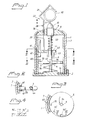
- the tool includes a generally tubular handgrip 1 that has a bottom 2 which carries a central pin 3, an end-part 10 of which extends out of the tool and carries a cutting blade 17.
- a body 7 is mounted for rotation relative to the handgrip 1 in the tubular tool 1.
- the body includes an end wall 8 that has a central opening 9 through which the end-part 10 of the pin extends.
- the end wall 8 has an opening 16 for receiving a straight shaft 20 whose end is connected to a carrier element 40 that can be moved axially relative to the body but that is non-rotatable in relation thereto.
- the carrier element 40 has an opening 44 through which the pin 3 extends.
- the element 40 includes a nose 41 that engages between two axially extending and parallel guide flanges 42 on the body 7.
- the hook 22 has a hook part 21 which is adapted to centre the cable 30 in relation to the cutting blade 17.
- a spring 50 acts axially between the end-part 10 of the pin 3 and the carrier element 40 such as to urge the cable 30 against the cutting blade 17 through the medium of the hook part 21 of the hook element 22.
- the bottom end-part of the pin 3 carries axial splines 4 which engage with corresponding axial splines 34 on an opening-defining wall 52 on a cam disc.
- the cam disc 5 can thus be moved axially along the pin 3 and is secured against rotation relative thereto as a result of the engagement between the spline formations 4, 34.
- the body 7 carries a cam follower 60 which co-acts with a peripheral region of the cam disc 5.
- a cam follower 60 which co-acts with a peripheral region of the cam disc 5.
- formations 70', 70" in which the cam follower 60 can engage.
- a pressure spring 4 Provided between the bottom part 2 of the handgrip and the cam disc 5 is a pressure spring 4 which biases the disc 5 into contact with the cam follower 60.
- a spring 51 which strives to return the handgrip 1 and the body 7 towards a mutual position of rotation in which the cam follower 60 rests on the upper side of the cam disc in a position 70 which, for instance, may correspond to the blade 17 lying in a plane normal to the axial direction of the cable 30.
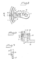
- the formation 70' (rounded recess) on the cam disc can define, in co-action with the cam follower 60, a cutting blade orientation in which the blade 17 cuts a helical slit in the cable casing as the tool (the hook 21) rotates about the cable axis.
- the third formation 70" corresponds to the cutting blade 17 lying in an axial plane of the cable 30.
- the cutting blade 17 can thus be set to stable positions of rotation relative to the body 7, with the aid of the recesses 70', 70" and the cam follower 60, and therewith relative to the hook 22, against the action of the spring 51.
- Fig. 1 shows a downwardly and forwardly projecting cylindrical part 43 on the carrier element 40.
- the hook and its carrier element 40 When the hook element 22 is released from a position in which the spring 50 is pressure-loaded, the hook and its carrier element 40 will move down into contact with the cam disc 5, wherein the characteristic and stroke length of the spring 50 is chosen so that the forwardly projecting part 43 of the carrier element will drive the cam disc 5 down against the action of its axial biasing spring 4, so that the disc 5 will pass free from its engagement with the cam follower 60.
- the spring 51 then returns the handgrip 1 and the body 7 to a normal position whilst the cam disc is out of contact with the cam follower.
- the spring 4 in combination with the curvatures of the cam follower 60 and the co-action of the recesses 70 can thus provide a retaining force against the action of the return spring 51.
- the cam follower 60 and the recesses 70 shall provide a wedging effect which results in axial displacement of the cam disc against the spring 4 in response to an applied torque.
- the carrier element 40 has an axially directed recess 45 which receives the bottom end-part of the hook stem 20.
- the nose part 41 of said element has a radially extending channel 46 which is aligned with an opening 72 in the body 7 and an opening 11 in the handgrip 1 when the tool is in its normal state, towards which it is biased by the spring 51.
- a spring tongue 47 affixed to the carrier element 40 carries a locking pin 48 which extends through a corresponding guide and into the channel 45 so as to be able to engage a latch opening 24 in the hook stem 20 when said stem is inserted down into the channel 45.
- the end of the hook stem 20 has a bevel 26 that forms a wedge surface which will function to move the locking pin 48 away as the hook stem 20 is inserted into the channel 45.
- the end-part of the hook stem includes a narrow, elongate rod portion 27.
- the rod portion 27 on the stem-end of a replacement hook 22 can be inserted through the openings 11, 72 and through the channel 26 so as to press the latch pin 28 to one side and out of the opening 24, whereafter the hook element 22 of said tool can be lifted up to pass free from the latch pin 48 and the rod 27 of the replacement hook can then be drawn out to permit continued withdrawal of the hook element 22 of said tool.
- the stem-part of the replacement hook can then be easily placed in position through the eccentric guide channel 16, and down into the receiving channel 45 of the carrier element, wherewith the spring element 47 causes the carrier pin 48 to engage with the opening 24 when the stem 16 is positioned correctly in the element 40.
- the bottom plate 2 of said handgrip may include a container for storing replacement cutting blades 17.
- the hook stem may have a shoulder or ledge 28 that co-acts with the upper side 8 of the body, so as to define a hook end position.
- the latch mechanism for fastening the hook stem will then be exposed through the openings.
- the spring 50 may be adapted to knock down the cam disc temporarily out of contact with the cam follower, although the spring 50 may alternatively be made stronger than the spring 76, so that the cam disc 5 will be held depressed at a distance beneath the cam follower 60 when the tool is unloaded (no cable in the hook).
- the hook stem 16 may have an abutment that co-acts with the upper side of the end-wall 8 of said body 7.
Landscapes
- Removal Of Insulation Or Armoring From Wires Or Cables (AREA)
- Knives (AREA)
Applications Claiming Priority (2)
| Application Number | Priority Date | Filing Date | Title |
|---|---|---|---|
| SE0104297A SE519152C2 (sv) | 2001-12-19 | 2001-12-19 | Kabelskalningsverktyg |
| SE0104297 | 2001-12-19 |
Publications (2)
| Publication Number | Publication Date |
|---|---|
| EP1322010A1 true EP1322010A1 (de) | 2003-06-25 |
| EP1322010B1 EP1322010B1 (de) | 2007-02-14 |
Family
ID=20286397
Family Applications (1)
| Application Number | Title | Priority Date | Filing Date |
|---|---|---|---|
| EP02445166A Expired - Lifetime EP1322010B1 (de) | 2001-12-19 | 2002-12-04 | Kabelabmantelungswerkzeug |
Country Status (5)
| Country | Link |
|---|---|
| US (1) | US6802125B2 (de) |
| EP (1) | EP1322010B1 (de) |
| AT (1) | ATE354196T1 (de) |
| DE (1) | DE60218115T2 (de) |
| SE (1) | SE519152C2 (de) |
Cited By (3)
| Publication number | Priority date | Publication date | Assignee | Title |
|---|---|---|---|---|
| EP2015416A1 (de) * | 2007-07-10 | 2009-01-14 | Rennsteig Werkzeuge GmbH | Kabelabmantelwerkzeug |
| CN103956690A (zh) * | 2013-05-24 | 2014-07-30 | 国家电网公司 | 使用绝缘导线绝缘层环切器切割绝缘层的方法 |
| CN115241810A (zh) * | 2022-09-23 | 2022-10-25 | 国网山东省电力公司高密市供电公司 | 一种配电箱电缆用剥皮装置及剥皮方法 |
Families Citing this family (2)
| Publication number | Priority date | Publication date | Assignee | Title |
|---|---|---|---|---|
| US20050102838A1 (en) * | 2005-02-20 | 2005-05-19 | David Leason | Clam Shell and Blister Package Opening Device and Method for Using Same |
| FR2992108B1 (fr) * | 2012-06-14 | 2014-06-13 | Stanley Works Europe Gmbh | Outil manuel perfectionne de denudage de cable |
Citations (2)
| Publication number | Priority date | Publication date | Assignee | Title |
|---|---|---|---|---|
| US5345681A (en) * | 1992-02-12 | 1994-09-13 | Weidmuller Interface Gmbh & Co. | Tool for stripping a conductor |
| US6073349A (en) * | 1995-09-13 | 2000-06-13 | Liversidge; Barry P. | Wire stripper |
Family Cites Families (8)
| Publication number | Priority date | Publication date | Assignee | Title |
|---|---|---|---|---|
| US1866095A (en) * | 1930-04-29 | 1932-07-05 | Western Electric Co | Cutting tool |
| US3535785A (en) * | 1968-02-26 | 1970-10-27 | James J Matthews | Cable scoring tool |
| GB1458366A (en) * | 1973-04-26 | 1976-12-15 | Bieganski Z | Tools for cutting |
| US3881249A (en) * | 1974-06-05 | 1975-05-06 | Ideal Ind | Cable stripper |
| SE460939B (sv) * | 1980-08-29 | 1989-12-04 | Ca Weidmueller Gmbh & Co | Verktyg foer avisolering av kabelaendar |
| DE3263749D1 (en) * | 1981-08-28 | 1985-06-27 | Weidmueller C A Gmbh Co | Wire stripping tool |
| GB2231732A (en) * | 1989-04-29 | 1990-11-21 | Barry Peter Liversidge | Wire stripping tool |
| US6334253B1 (en) * | 2000-08-28 | 2002-01-01 | Yin-Ho Cheng | Adjustable wire stripper |
-
2001
- 2001-12-19 SE SE0104297A patent/SE519152C2/sv not_active IP Right Cessation
-
2002
- 2002-12-02 US US10/307,375 patent/US6802125B2/en not_active Expired - Lifetime
- 2002-12-04 EP EP02445166A patent/EP1322010B1/de not_active Expired - Lifetime
- 2002-12-04 DE DE60218115T patent/DE60218115T2/de not_active Expired - Lifetime
- 2002-12-04 AT AT02445166T patent/ATE354196T1/de not_active IP Right Cessation
Patent Citations (2)
| Publication number | Priority date | Publication date | Assignee | Title |
|---|---|---|---|---|
| US5345681A (en) * | 1992-02-12 | 1994-09-13 | Weidmuller Interface Gmbh & Co. | Tool for stripping a conductor |
| US6073349A (en) * | 1995-09-13 | 2000-06-13 | Liversidge; Barry P. | Wire stripper |
Cited By (5)
| Publication number | Priority date | Publication date | Assignee | Title |
|---|---|---|---|---|
| EP2015416A1 (de) * | 2007-07-10 | 2009-01-14 | Rennsteig Werkzeuge GmbH | Kabelabmantelwerkzeug |
| CN103956690A (zh) * | 2013-05-24 | 2014-07-30 | 国家电网公司 | 使用绝缘导线绝缘层环切器切割绝缘层的方法 |
| CN103956690B (zh) * | 2013-05-24 | 2016-03-02 | 国家电网公司 | 使用绝缘导线绝缘层环切器切割绝缘层的方法 |
| CN115241810A (zh) * | 2022-09-23 | 2022-10-25 | 国网山东省电力公司高密市供电公司 | 一种配电箱电缆用剥皮装置及剥皮方法 |
| CN115241810B (zh) * | 2022-09-23 | 2022-12-02 | 国网山东省电力公司高密市供电公司 | 一种配电箱电缆用剥皮装置及剥皮方法 |
Also Published As
| Publication number | Publication date |
|---|---|
| US20030110636A1 (en) | 2003-06-19 |
| SE0104297L (sv) | 2003-01-21 |
| ATE354196T1 (de) | 2007-03-15 |
| SE519152C2 (sv) | 2003-01-21 |
| SE0104297D0 (sv) | 2001-12-19 |
| DE60218115D1 (de) | 2007-03-29 |
| DE60218115T2 (de) | 2007-06-21 |
| US6802125B2 (en) | 2004-10-12 |
| EP1322010B1 (de) | 2007-02-14 |
Similar Documents
| Publication | Publication Date | Title |
|---|---|---|
| DE2354168C2 (de) | Werkzeughalter für einen Bohrhammer | |
| EP0775036B1 (de) | Schnellentriegelungsmechanismus für werkzeuge wie z.b. schraubenschlüssel | |
| EP2163357B1 (de) | Zusatzhandgriff für eine Handwerkzeugmaschine | |
| CA2107858C (en) | Quick release mechanism for tools such as socket wrenches | |
| US5934139A (en) | Bi-directional impact tool | |
| SE459635B (sv) | Drivaggregat foer en anordning foer vaevnadsprovtagning | |
| WO1998048178A1 (en) | An adjustable tool with a locking hinge mechanism | |
| EP1324447A2 (de) | Kabelabmantelungswerkzeug | |
| EP1322010B1 (de) | Kabelabmantelungswerkzeug | |
| EP1427570B1 (de) | Extraktionswerkzeug für mit griff versehene schraubenförmig gewundene einsätze | |
| US6196103B1 (en) | Punch guide assembly | |
| WO2011104105A1 (de) | Handwerkzeugmaschine | |
| DE10109956A1 (de) | Handwerkzeugmaschine | |
| CA2138844C (en) | Quick release mechanism for tools such as socket wrenches | |
| EP1582297B1 (de) | Selbstverriegelnde Kurbel für eine Winde | |
| DE1255059B (de) | Montagewerkzeug fuer eine Blindschraubenverbindung | |
| EP2683512B1 (de) | Schnellwechselsystem für ein drehbares werkzeug und basis eines solchen systems | |
| DE10260324B4 (de) | Elektrisches Werkzeug | |
| US6219883B1 (en) | Locking assembly for push broom | |
| EP0940210A1 (de) | Sägeblattspannvorrichtung und Säge versehen mit dieser Vorrichtung | |
| EP4480650B1 (de) | Fleisch-trimmer, kupplungsanordnung hierfür sowie verwendung derselben | |
| DE102006015274B4 (de) | Bohrwerkzeuggerät | |
| CA2120856C (en) | Quick release mechanism for tools such as socket wrenches | |
| DE8913081U1 (de) | Vorrichtung zum manuellen Starten eines Verbrennungsmotors eines Rasenmähers o.dgl. | |
| CN113910164A (zh) | 一种深通道内扣拧紧工具 |
Legal Events
| Date | Code | Title | Description |
|---|---|---|---|
| PUAI | Public reference made under article 153(3) epc to a published international application that has entered the european phase |
Free format text: ORIGINAL CODE: 0009012 |
|
| AK | Designated contracting states |
Designated state(s): AT BE BG CH CY CZ DE DK EE ES FI FR GB GR IE IT LI LU MC NL PT SE SI SK TR |
|
| AX | Request for extension of the european patent |
Extension state: AL LT LV MK RO |
|
| 17P | Request for examination filed |
Effective date: 20031129 |
|
| AKX | Designation fees paid |
Designated state(s): AT BE BG CH CY CZ DE DK EE ES FI FR GB GR IE IT LI LU MC NL PT SE SI SK TR |
|
| GRAP | Despatch of communication of intention to grant a patent |
Free format text: ORIGINAL CODE: EPIDOSNIGR1 |
|
| GRAS | Grant fee paid |
Free format text: ORIGINAL CODE: EPIDOSNIGR3 |
|
| GRAA | (expected) grant |
Free format text: ORIGINAL CODE: 0009210 |
|
| AK | Designated contracting states |
Kind code of ref document: B1 Designated state(s): AT BE BG CH CY CZ DE DK EE ES FI FR GB GR IE IT LI LU MC NL PT SE SI SK TR |
|
| PG25 | Lapsed in a contracting state [announced via postgrant information from national office to epo] |
Ref country code: DK Free format text: LAPSE BECAUSE OF FAILURE TO SUBMIT A TRANSLATION OF THE DESCRIPTION OR TO PAY THE FEE WITHIN THE PRESCRIBED TIME-LIMIT Effective date: 20070214 Ref country code: FI Free format text: LAPSE BECAUSE OF FAILURE TO SUBMIT A TRANSLATION OF THE DESCRIPTION OR TO PAY THE FEE WITHIN THE PRESCRIBED TIME-LIMIT Effective date: 20070214 Ref country code: SI Free format text: LAPSE BECAUSE OF FAILURE TO SUBMIT A TRANSLATION OF THE DESCRIPTION OR TO PAY THE FEE WITHIN THE PRESCRIBED TIME-LIMIT Effective date: 20070214 Ref country code: NL Free format text: LAPSE BECAUSE OF FAILURE TO SUBMIT A TRANSLATION OF THE DESCRIPTION OR TO PAY THE FEE WITHIN THE PRESCRIBED TIME-LIMIT Effective date: 20070214 Ref country code: BE Free format text: LAPSE BECAUSE OF FAILURE TO SUBMIT A TRANSLATION OF THE DESCRIPTION OR TO PAY THE FEE WITHIN THE PRESCRIBED TIME-LIMIT Effective date: 20070214 Ref country code: AT Free format text: LAPSE BECAUSE OF FAILURE TO SUBMIT A TRANSLATION OF THE DESCRIPTION OR TO PAY THE FEE WITHIN THE PRESCRIBED TIME-LIMIT Effective date: 20070214 Ref country code: LI Free format text: LAPSE BECAUSE OF FAILURE TO SUBMIT A TRANSLATION OF THE DESCRIPTION OR TO PAY THE FEE WITHIN THE PRESCRIBED TIME-LIMIT Effective date: 20070214 Ref country code: CH Free format text: LAPSE BECAUSE OF FAILURE TO SUBMIT A TRANSLATION OF THE DESCRIPTION OR TO PAY THE FEE WITHIN THE PRESCRIBED TIME-LIMIT Effective date: 20070214 |
|
| REG | Reference to a national code |
Ref country code: GB Ref legal event code: FG4D |
|
| REG | Reference to a national code |
Ref country code: CH Ref legal event code: EP |
|
| REF | Corresponds to: |
Ref document number: 60218115 Country of ref document: DE Date of ref document: 20070329 Kind code of ref document: P |
|
| REG | Reference to a national code |
Ref country code: IE Ref legal event code: FG4D |
|
| PG25 | Lapsed in a contracting state [announced via postgrant information from national office to epo] |
Ref country code: SE Free format text: LAPSE BECAUSE OF FAILURE TO SUBMIT A TRANSLATION OF THE DESCRIPTION OR TO PAY THE FEE WITHIN THE PRESCRIBED TIME-LIMIT Effective date: 20070514 |
|
| PG25 | Lapsed in a contracting state [announced via postgrant information from national office to epo] |
Ref country code: BG Free format text: LAPSE BECAUSE OF THE APPLICANT RENOUNCES Effective date: 20070515 |
|
| PG25 | Lapsed in a contracting state [announced via postgrant information from national office to epo] |
Ref country code: ES Free format text: LAPSE BECAUSE OF FAILURE TO SUBMIT A TRANSLATION OF THE DESCRIPTION OR TO PAY THE FEE WITHIN THE PRESCRIBED TIME-LIMIT Effective date: 20070525 |
|
| ET | Fr: translation filed | ||
| PG25 | Lapsed in a contracting state [announced via postgrant information from national office to epo] |
Ref country code: PT Free format text: LAPSE BECAUSE OF FAILURE TO SUBMIT A TRANSLATION OF THE DESCRIPTION OR TO PAY THE FEE WITHIN THE PRESCRIBED TIME-LIMIT Effective date: 20070716 |
|
| NLV1 | Nl: lapsed or annulled due to failure to fulfill the requirements of art. 29p and 29m of the patents act | ||
| REG | Reference to a national code |
Ref country code: CH Ref legal event code: PL |
|
| PG25 | Lapsed in a contracting state [announced via postgrant information from national office to epo] |
Ref country code: SK Free format text: LAPSE BECAUSE OF FAILURE TO SUBMIT A TRANSLATION OF THE DESCRIPTION OR TO PAY THE FEE WITHIN THE PRESCRIBED TIME-LIMIT Effective date: 20070214 |
|
| PLBE | No opposition filed within time limit |
Free format text: ORIGINAL CODE: 0009261 |
|
| STAA | Information on the status of an ep patent application or granted ep patent |
Free format text: STATUS: NO OPPOSITION FILED WITHIN TIME LIMIT |
|
| PG25 | Lapsed in a contracting state [announced via postgrant information from national office to epo] |
Ref country code: CZ Free format text: LAPSE BECAUSE OF FAILURE TO SUBMIT A TRANSLATION OF THE DESCRIPTION OR TO PAY THE FEE WITHIN THE PRESCRIBED TIME-LIMIT Effective date: 20070214 |
|
| 26N | No opposition filed |
Effective date: 20071115 |
|
| PG25 | Lapsed in a contracting state [announced via postgrant information from national office to epo] |
Ref country code: GR Free format text: LAPSE BECAUSE OF FAILURE TO SUBMIT A TRANSLATION OF THE DESCRIPTION OR TO PAY THE FEE WITHIN THE PRESCRIBED TIME-LIMIT Effective date: 20070515 |
|
| PG25 | Lapsed in a contracting state [announced via postgrant information from national office to epo] |
Ref country code: MC Free format text: LAPSE BECAUSE OF NON-PAYMENT OF DUE FEES Effective date: 20071231 |
|
| PG25 | Lapsed in a contracting state [announced via postgrant information from national office to epo] |
Ref country code: IE Free format text: LAPSE BECAUSE OF NON-PAYMENT OF DUE FEES Effective date: 20071204 |
|
| PG25 | Lapsed in a contracting state [announced via postgrant information from national office to epo] |
Ref country code: EE Free format text: LAPSE BECAUSE OF FAILURE TO SUBMIT A TRANSLATION OF THE DESCRIPTION OR TO PAY THE FEE WITHIN THE PRESCRIBED TIME-LIMIT Effective date: 20070214 |
|
| PG25 | Lapsed in a contracting state [announced via postgrant information from national office to epo] |
Ref country code: CY Free format text: LAPSE BECAUSE OF FAILURE TO SUBMIT A TRANSLATION OF THE DESCRIPTION OR TO PAY THE FEE WITHIN THE PRESCRIBED TIME-LIMIT Effective date: 20070214 |
|
| PG25 | Lapsed in a contracting state [announced via postgrant information from national office to epo] |
Ref country code: LU Free format text: LAPSE BECAUSE OF NON-PAYMENT OF DUE FEES Effective date: 20071204 |
|
| PG25 | Lapsed in a contracting state [announced via postgrant information from national office to epo] |
Ref country code: TR Free format text: LAPSE BECAUSE OF FAILURE TO SUBMIT A TRANSLATION OF THE DESCRIPTION OR TO PAY THE FEE WITHIN THE PRESCRIBED TIME-LIMIT Effective date: 20070214 |
|
| REG | Reference to a national code |
Ref country code: FR Ref legal event code: PLFP Year of fee payment: 14 |
|
| REG | Reference to a national code |
Ref country code: FR Ref legal event code: PLFP Year of fee payment: 15 |
|
| REG | Reference to a national code |
Ref country code: FR Ref legal event code: PLFP Year of fee payment: 16 |
|
| PGFP | Annual fee paid to national office [announced via postgrant information from national office to epo] |
Ref country code: DE Payment date: 20211222 Year of fee payment: 20 Ref country code: GB Payment date: 20211221 Year of fee payment: 20 Ref country code: FR Payment date: 20211215 Year of fee payment: 20 |
|
| PGFP | Annual fee paid to national office [announced via postgrant information from national office to epo] |
Ref country code: IT Payment date: 20211217 Year of fee payment: 20 |
|
| REG | Reference to a national code |
Ref country code: DE Ref legal event code: R071 Ref document number: 60218115 Country of ref document: DE |
|
| REG | Reference to a national code |
Ref country code: GB Ref legal event code: PE20 Expiry date: 20221203 |
|
| PG25 | Lapsed in a contracting state [announced via postgrant information from national office to epo] |
Ref country code: GB Free format text: LAPSE BECAUSE OF EXPIRATION OF PROTECTION Effective date: 20221203 |