EP1322012A1 - Dispositif de fixation en surface d'un interface d'installation domestique - Google Patents
Dispositif de fixation en surface d'un interface d'installation domestique Download PDFInfo
- Publication number
- EP1322012A1 EP1322012A1 EP01129394A EP01129394A EP1322012A1 EP 1322012 A1 EP1322012 A1 EP 1322012A1 EP 01129394 A EP01129394 A EP 01129394A EP 01129394 A EP01129394 A EP 01129394A EP 1322012 A1 EP1322012 A1 EP 1322012A1
- Authority
- EP
- European Patent Office
- Prior art keywords
- holding means
- fastening
- installation interface
- interface
- plate
- Prior art date
- Legal status (The legal status is an assumption and is not a legal conclusion. Google has not performed a legal analysis and makes no representation as to the accuracy of the status listed.)
- Granted
Links
- 238000009434 installation Methods 0.000 title claims description 31
- 210000002105 tongue Anatomy 0.000 claims description 46
- 230000003287 optical effect Effects 0.000 claims description 4
- 238000003825 pressing Methods 0.000 description 2
- 238000004026 adhesive bonding Methods 0.000 description 1
- 230000015572 biosynthetic process Effects 0.000 description 1
- 230000000881 depressing effect Effects 0.000 description 1
- 238000005755 formation reaction Methods 0.000 description 1
- 238000003780 insertion Methods 0.000 description 1
- 230000037431 insertion Effects 0.000 description 1
- 238000004519 manufacturing process Methods 0.000 description 1
- 230000000717 retained effect Effects 0.000 description 1
- 238000003892 spreading Methods 0.000 description 1
Images


Classifications
-
- H—ELECTRICITY
- H02—GENERATION; CONVERSION OR DISTRIBUTION OF ELECTRIC POWER
- H02G—INSTALLATION OF ELECTRIC CABLES OR LINES, OR OF COMBINED OPTICAL AND ELECTRIC CABLES OR LINES
- H02G3/00—Installations of electric cables or lines or protective tubing therefor in or on buildings, equivalent structures or vehicles
- H02G3/02—Details
- H02G3/08—Distribution boxes; Connection or junction boxes
- H02G3/10—Distribution boxes; Connection or junction boxes for surface mounting on a wall
Definitions
- the invention relates to a fastening arrangement for surface mounting an electrical and / or optical home installation interface on a wall according to the preamble of claim 1 and a mounting plate such an arrangement according to claim 11.
- Home installation interfaces for electrical and / or optical lines include e.g. Interfaces (also known as apparatus) for mains voltage, like sockets or switches, or for phone, Radio, television and data lines.
- Interfaces also known as apparatus
- Flush mounting of such interfaces becomes an inlet box fixed in a wall recess, in which box the interface, e.g. a light switch and / or a socket to be connected to cables are.
- box the interface e.g. a light switch and / or a socket to be connected to cables are. It is proposed in CH-A-585 472 or CH-A-647 898 the devices by means of retaining springs or Spreading clamps without screw fastening in the inlet box mountable.
- the pipes are installed using installation pipes laid on the masonry and the apparatus are screwed directly onto the wall or for precise positioning Installation preferably using a mounting bracket or a mounting plate attached to the wall, wherein first screwed the bracket or plate to the wall and then the apparatus with the bracket or the plate is screwed.
- the latter Screw connections with threaded holes and small ones Screws result in high manufacturing and assembly costs. Tool-free attachment of the device the house installation interface on the mounting plate would therefore be desirable.
- the retaining springs or There are no expansion brackets for flush mounting an inlet box is obviously unsuitable and the provision of a box on the wall proves to be complex and impractical for the line connection.
- CH-A-654 147 suggests a tool-free installation of a surface-mounted socket at poorly accessible installation locations using Velcro or magnets or by means of a clamping rail before, the clamping rail angled guides has, in which side flanges of the socket housing be introduced. The tours widen when inserting the flanges spring something up and hold so the socket housing is clamped, in the direction of pull of the connector the angulation of the guides one Otherwise there is a positive connection that holds the socket but only a non-positive hold takes place.
- Such an attachment is for a normally accessible Apparatus on a wall, which is also suitable for frequent use must not be used and is therefore in the state the technology for mounting sockets in intermediate floors proposed where use of the Interface by inserting and pulling out a Connector.
- the invention is therefore based on the object a possibility of mounting an interface to create a wall that is also tool-free Assembly step includes, but the disadvantages mentioned does not have and a permanently secure attachment results in the wall and thus for generally accessible, normal usable interfaces (sockets, switches) good suitable is.
- holding means and separate locking means are provided, can be locked Interface in their final position, what results in a defined assembly position in the end position and a secure attachment, even with frequent use the interface has a defined permanent position the interface guaranteed.
- the holding and latching means are preferably designed so that the assembly of the interface by rotating the same or by moving it the same takes place, these movements essentially only over the base of the mounting plate take place, so that this assembly essentially only the Space above the mounting plate is required and therefore through the installation pipes and possibly next to the mounting plate existing door frames not difficult or is made impossible. It is also preferred if the assembly movements of the holding or locking means will that from different, especially two different starting positions when attaching the to be assembled Home installation interface on the mounting plate are moved to the defined end position can also do the assembly next to the mounting plate elements on the wall (door frame, Lines) facilitated.
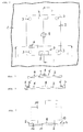
- the mounting plate 2 permanently attached to the wall.
- the mounting plate 2 now has on the one hand the holding means 4, 5 on, and locking means 6 and 7.
- the holding means 4, 5 which is used to differentiate the holding means the installation interface as the first holding device can be referred to as two angled Formations 4, 5 of the mounting plate is carried out, which each have an undercut or a groove 4 'or 5 'have.
- the grooves 4 'and 5' are in this embodiment each also open at the front and point as shown in the section of Figure 2, a curved Groove bottom on.
- the first holding means as a rigid, with the Mounting plate 2 is one-piece bends 4, 5 of course only to be understood as an example.
- the holding device 4, 5 could also be separate, attached to the mounting plate Have parts and these could e.g. also as flexible spring tongues can be executed, which the surface act on the mounting plate, which follows will be explained later.
- the one shown in this example Locking means comprises a resilient tongue 6, which in the shown example also in one piece with the mounting plate 2 is trained and in their rest position rises above their surface and when loaded in the mounting plate 2 can be pushed in, as in Section of Figure 3 can be seen.
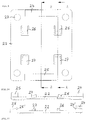
- FIG 4 shows a home installation interface 10, which in this example is an electrical one Switch, especially a light switch.
- This Interface 10 also has a holding means, which distinguishes the first holding means 4, 5 can be referred to as a second holding means.
- This is designed to interact with the first holding means and is in the example shown as plate 11 executed, which two arranged opposite each other Tongues 12 and 13, the tongue 13 in the sectional view of Figure 7 can be seen.
- the Tongues 12 and 13 of the second holding means are for engagement with the grooves 5 'and 4' of the first holding means trained, as can be seen below.
- the Execution of the second holding means as from the housing of the Interface 10 separate plate, which on the actual Housing is attached, e.g. by screwing or Gluing or otherwise is only an example too consider.
- the second fastener could also made in one piece with the housing of the interface 10 his; for example the wings 12 and 13 parts of the housing of the interface 10.
- FIG. 4 shows the interface 10 above the wall mounting plate 2 shortly before the actual tool-free surface mounting begins the interface 10 on the wall by means of the fastening arrangement.
- Figure 5 shows how the interface 10 in the slightly twisted position shown the plate 11 on the surface of the mounting plate 2 has been positioned, which is done by the fitter by hand.
- the spring tongue 6 is in the mounting plate 2 pushed in. From the twisted position of Figure 5 can now by rotating or rotating the interface 10 counterclockwise on the mounting plate are brought into the final assembly position, which is shown in Figure 6.
- When rotating the Interface 10 drive the wings 12 and 13 in the grooves 5 'or 4' of the first holding means, so that this positive locking of the interface 10 in the direction perpendicular to the wall.
- the interface 10 is thus by the first and second holding means 4, 5 or 12, 13 fixed in the direction perpendicular to the wall, like this is particularly evident from FIG. 7, and by the locking means 6 and 7 in the final assembly position, so that there is a precisely defined position of the interface.
- this can preferably the assembly is done so that the interface from above the mounting plate 2 on this is placed so that no entry into the assembly position necessary from one side of the mounting plate is.
- This is particularly preferred, as it is often alongside a door frame runs on the mounting plate on the wall and also the surface conduit run, so that a Entry from one of the four sides of plate 2 only would be difficult or impossible what the use restrict the mounting arrangement according to the invention would.
- the assembly position is also predetermined such that from the inclined position shown counterclockwise must be installed.
- the center of rotation is specified, e.g. through a Pin 8 on the mounting plate and a corresponding one Recess at the interface 10 or vice versa.
- locking means can also be at the interface 10 be arranged and includes e.g. also a spring tongue, which when pressed in accordance with FIG Interface is pushed in and which one is reached the end position in a recess of the mounting plate 2 springs into it.
- Disassembly is also necessary in this case possible again by unlatching the locking means is, in the case just described, by this spring tongue is levered out of the recess at the interface, in the case shown in the figures, by the spring tongue 6 into the mounting plate by hand or using a tool 6 is pushed in so that disassembly by turning clockwise, which makes the position of FIG. 5 again results, from which the interface 10 removed from the mounting plate can be.
- FIGS. 8-16 Embodiment explained, in which the first and second holding means are designed so that an assembly done by translational movement.
- Figure 8 shows again a mounting plate 22 on a wall 1, the plate is fastened by screws through the screw holes 23 on the wall.
- the first holding means is here by bridge-like Parts 24 and 25 formed which are integral with the Mounting plate or can be attached to this. Continuously open recesses 24 'and 25' are on the one hand from the surface of the plate 22 and on the other hand bounded by the underside of the respective bridge 25 and are limited on the front by the pillars of the bridges.
- Spring tongues 26 and 27 are provided here as latching means.
- Figures 9, 10 and 11 show a top view the mounting plate of Figure 8 or a section along the line A-A or B-B.
- Figure 11 the shape of the recesses 24 'and 25' can be seen, which preferably at their towards the middle of the plate open end expanded compared to the plate edge end are.
- Figures 12-15 now show the assembly an interface 30, which in turn also Light switch is provided with a second holding means which is a plate 31 in this example Tongues 32 and 33 is.
- This holding means can in turn in one piece with the housing of the interface 30 or attached as a separate part to this his.
- Figures 12 and 13 show how at the start of assembly the interface 30 in turn from above over the mounting plate 22 can be placed, this in angled Position takes place so that the tongue 33 in the recess 24 'can be retracted under the bridge 24, as shown in Figures 12 and 13.
- the Interface 30 is then pressed down to plate 22, so that the spring tongues 26, which are located under the plate 31, in the mounting plate 22 are pushed in.
- the wing 32 extends between the spring tongues 27, which therefore when pressing the interface 30 down on the mounting plate 22 can still be extended, like this can be seen in Figure 14.
- the interface 30 is now moved in the direction of arrow A, the Tongue 32 moves into the recess 25 '.
- the postponement is as far as possible until the plate 31 on the spring tongues 27, which serve here as fixed stops.
- the tongues 32 and 33 are among the Bridges 25 and 24 retracted, which by the first and second holding means holding the installation interface in the direction perpendicular to the wall and the spring tongues 26 are in turn from the mounting plate 22 extended because they are released from the plate 31 have become, whereby the plate 31 snaps into place between the spring tongues 26 and 27 of the locking means in the Final assembly position results.
- the assembly could also be done by the other side than shown, so that by opposite slope than shown in Figures 12 and 13 first the tongue 32 is inserted under the holding bridge 25 and by depressing the interface 30 the spring tongues 27 are pressed into the plate 22, which is followed by the shifting movement the arrow A, so that the tongue 33 under the Bridge 24 retracts and interface 30 at the stops 26 is pending and the spring tongues 27 in the end position be released.
- Disassembly is again by pressing down one or the other spring tongue 26 or 27 possible.
- too Latching means can be arranged at the interface, like this roughly by a schematically shown spring tongue 26 'on the plate 31 and a recess 27' in the plate 22 is indicated in Figure 13.
Landscapes
- Engineering & Computer Science (AREA)
- Architecture (AREA)
- Civil Engineering (AREA)
- Structural Engineering (AREA)
- Casings For Electric Apparatus (AREA)
- Hooks, Suction Cups, And Attachment By Adhesive Means (AREA)
- Selective Calling Equipment (AREA)
- Devices For Indicating Variable Information By Combining Individual Elements (AREA)
- Distribution Board (AREA)
- Details Of Indoor Wiring (AREA)
- Mounting Components In General For Electric Apparatus (AREA)
Priority Applications (5)
| Application Number | Priority Date | Filing Date | Title |
|---|---|---|---|
| DK01129394T DK1322012T3 (da) | 2001-12-18 | 2001-12-18 | Fastgörelsesanordning til synlig montering af en hjemmeinstallationsgrænseflade |
| AT01129394T ATE440397T1 (de) | 2001-12-18 | 2001-12-18 | Befestigungsanordnung zur aufputzmontage einer hausinstallationsschnittstelle |
| DE50115061T DE50115061D1 (de) | 2001-12-18 | 2001-12-18 | Befestigungsanordnung zur Aufputzmontage einer Hausinstallationsschnittstelle |
| EP01129394A EP1322012B1 (fr) | 2001-12-18 | 2001-12-18 | Dispositif de fixation en surface d'un interface d'installation domestique |
| NO20025874A NO20025874L (no) | 2001-12-18 | 2002-12-06 | Festeanordning til utenpåliggende montasje av et husinstallasjonsgrensesnitt |
Applications Claiming Priority (1)
| Application Number | Priority Date | Filing Date | Title |
|---|---|---|---|
| EP01129394A EP1322012B1 (fr) | 2001-12-18 | 2001-12-18 | Dispositif de fixation en surface d'un interface d'installation domestique |
Publications (2)
| Publication Number | Publication Date |
|---|---|
| EP1322012A1 true EP1322012A1 (fr) | 2003-06-25 |
| EP1322012B1 EP1322012B1 (fr) | 2009-08-19 |
Family
ID=8179496
Family Applications (1)
| Application Number | Title | Priority Date | Filing Date |
|---|---|---|---|
| EP01129394A Expired - Lifetime EP1322012B1 (fr) | 2001-12-18 | 2001-12-18 | Dispositif de fixation en surface d'un interface d'installation domestique |
Country Status (5)
| Country | Link |
|---|---|
| EP (1) | EP1322012B1 (fr) |
| AT (1) | ATE440397T1 (fr) |
| DE (1) | DE50115061D1 (fr) |
| DK (1) | DK1322012T3 (fr) |
| NO (1) | NO20025874L (fr) |
Cited By (4)
| Publication number | Priority date | Publication date | Assignee | Title |
|---|---|---|---|---|
| DE102004049971B4 (de) * | 2004-10-14 | 2007-12-06 | Insta Elektro Gmbh | Vorrichtung |
| EP2006966A1 (fr) * | 2007-06-22 | 2008-12-24 | C & C Marshall Limited | Système de distribution électrique et de service |
| FR2931017A1 (fr) * | 2008-05-06 | 2009-11-13 | Legrand France | Dispositif electrique mural a fixation et branchement independants |
| EP2009756A3 (fr) * | 2007-06-25 | 2016-10-19 | Abb Ag | Socle d'un appareil d'installation destiné à la réception d'éléments de contact électriques |
Citations (6)
| Publication number | Priority date | Publication date | Assignee | Title |
|---|---|---|---|---|
| DE1590141A1 (de) | 1966-07-28 | 1970-04-16 | Berker Geb | Befestigung eines Installationsgeraetes,insbesondere gekapselten Installationsgeraetes,an einer Flaeche |
| CH585472A5 (fr) | 1975-09-08 | 1977-02-28 | Feller Ag Adolf | |
| CH647898A5 (en) | 1979-06-27 | 1985-02-15 | Reichle & De Massari Fa | Device for screwless attachment of an electrical installation means, especially a plug socket, in an insertion box which is open at the front |
| CH654147A5 (en) | 1985-06-24 | 1986-01-31 | Schweizerische Kreditanstalt Z | Plug socket for mounting at points where access is difficult, and an attachment device for plug sockets and use of the same |
| EP0798834A1 (fr) | 1996-03-30 | 1997-10-01 | TEMIC TELEFUNKEN microelectronic GmbH | Boîte avec un dispositif d'attachement à une platine de montage |
| EP1050939A1 (fr) | 1999-05-06 | 2000-11-08 | Palazzoli S.p.A. | Systeme modulaire d'attache rapide pour dispositifs electriques |
-
2001
- 2001-12-18 EP EP01129394A patent/EP1322012B1/fr not_active Expired - Lifetime
- 2001-12-18 DE DE50115061T patent/DE50115061D1/de not_active Expired - Fee Related
- 2001-12-18 AT AT01129394T patent/ATE440397T1/de not_active IP Right Cessation
- 2001-12-18 DK DK01129394T patent/DK1322012T3/da active
-
2002
- 2002-12-06 NO NO20025874A patent/NO20025874L/no not_active Application Discontinuation
Patent Citations (6)
| Publication number | Priority date | Publication date | Assignee | Title |
|---|---|---|---|---|
| DE1590141A1 (de) | 1966-07-28 | 1970-04-16 | Berker Geb | Befestigung eines Installationsgeraetes,insbesondere gekapselten Installationsgeraetes,an einer Flaeche |
| CH585472A5 (fr) | 1975-09-08 | 1977-02-28 | Feller Ag Adolf | |
| CH647898A5 (en) | 1979-06-27 | 1985-02-15 | Reichle & De Massari Fa | Device for screwless attachment of an electrical installation means, especially a plug socket, in an insertion box which is open at the front |
| CH654147A5 (en) | 1985-06-24 | 1986-01-31 | Schweizerische Kreditanstalt Z | Plug socket for mounting at points where access is difficult, and an attachment device for plug sockets and use of the same |
| EP0798834A1 (fr) | 1996-03-30 | 1997-10-01 | TEMIC TELEFUNKEN microelectronic GmbH | Boîte avec un dispositif d'attachement à une platine de montage |
| EP1050939A1 (fr) | 1999-05-06 | 2000-11-08 | Palazzoli S.p.A. | Systeme modulaire d'attache rapide pour dispositifs electriques |
Cited By (4)
| Publication number | Priority date | Publication date | Assignee | Title |
|---|---|---|---|---|
| DE102004049971B4 (de) * | 2004-10-14 | 2007-12-06 | Insta Elektro Gmbh | Vorrichtung |
| EP2006966A1 (fr) * | 2007-06-22 | 2008-12-24 | C & C Marshall Limited | Système de distribution électrique et de service |
| EP2009756A3 (fr) * | 2007-06-25 | 2016-10-19 | Abb Ag | Socle d'un appareil d'installation destiné à la réception d'éléments de contact électriques |
| FR2931017A1 (fr) * | 2008-05-06 | 2009-11-13 | Legrand France | Dispositif electrique mural a fixation et branchement independants |
Also Published As
| Publication number | Publication date |
|---|---|
| NO20025874D0 (no) | 2002-12-06 |
| EP1322012B1 (fr) | 2009-08-19 |
| ATE440397T1 (de) | 2009-09-15 |
| DE50115061D1 (de) | 2009-10-01 |
| DK1322012T3 (da) | 2009-11-16 |
| NO20025874L (no) | 2003-06-19 |
Similar Documents
| Publication | Publication Date | Title |
|---|---|---|
| DE3214528C2 (de) | Vorrichtung zur Festlegung von Instrumentengehäusen in einer Trägerplatte | |
| EP1418652A1 (fr) | Dispositif de fixation pour connecteur | |
| EP1994614B1 (fr) | Construction a cadre pour une armoire electrique, armoire electrique et kit pour l'armoire electrique | |
| DE102006057766B4 (de) | Befestigungsvorrichtung von Elektronikmodulen auf Tragschiene | |
| DE20300637U1 (de) | Verbinder für Profile und Verbindungsanordnung | |
| EP1322012B1 (fr) | Dispositif de fixation en surface d'un interface d'installation domestique | |
| AT526098A2 (de) | Befestigungseinrichtung zum Befestigen einer Leuchtbaugruppe sowie Beleuchtungsanordnung mit mindestens einer derartigen Befestigungseinrichtung | |
| DE19540111B4 (de) | Elektronik- und Instrumentierungsgehäuse | |
| DE2835952A1 (de) | Elektrisches versorgungssystem | |
| DE3717363A1 (de) | Einbaudose zum montieren in einer kabelschiene | |
| DE102005022441B4 (de) | Kanal-Steckdose | |
| DE4012442C2 (fr) | ||
| DE4438477C2 (de) | Gehäuse, insbesondere für Elektronikeinbauten | |
| EP1089412B1 (fr) | Appareil d'installation avec des griffes de coincement rétractables | |
| DE202007016981U1 (de) | Befestigungsvorrichtung für ein elektrotechnisches Bauteil | |
| DE3938337A1 (de) | Fernmeldetechnische installationsdose | |
| DE20217322U1 (de) | Hohlwanddose | |
| DE69619021T2 (de) | Gehäuse eines elektrischen Gerätes | |
| DE29808857U1 (de) | Steckdosenleiste | |
| DE102024100353B4 (de) | Leuchte mit verriegelbarem Befestigungsabgriff und Verfahren zur Montage einer Leuchte | |
| EP1005263B1 (fr) | Dispositif de fixation d'un appareil électronique, ou son cadre-support dans l'ouverture d'une façade | |
| DE3834448A1 (de) | Haltevorrichtung insbesondere fuer einbaugeraete in kraftfahrzeuge | |
| DE19916074A1 (de) | Elektrische Steckverbindung, insbesondere für Kfz-Anwendungen | |
| DE202006020037U1 (de) | Rahmenkonstruktion für einen Schaltschrank, Schaltschrank und Bausatz für den Schaltschrank | |
| DE19932850C1 (de) | Befestigungssystem für elektrische Anlagen |
Legal Events
| Date | Code | Title | Description |
|---|---|---|---|
| PUAI | Public reference made under article 153(3) epc to a published international application that has entered the european phase |
Free format text: ORIGINAL CODE: 0009012 |
|
| AK | Designated contracting states |
Designated state(s): AT BE CH CY DE DK ES FI FR GB GR IE IT LI LU MC NL PT SE TR |
|
| AX | Request for extension of the european patent |
Extension state: AL LT LV MK RO SI |
|
| 17P | Request for examination filed |
Effective date: 20031204 |
|
| AKX | Designation fees paid |
Designated state(s): AT BE CH CY DE DK ES FI FR GB GR IE IT LI LU MC NL PT SE TR |
|
| 17Q | First examination report despatched |
Effective date: 20071213 |
|
| GRAP | Despatch of communication of intention to grant a patent |
Free format text: ORIGINAL CODE: EPIDOSNIGR1 |
|
| GRAS | Grant fee paid |
Free format text: ORIGINAL CODE: EPIDOSNIGR3 |
|
| GRAA | (expected) grant |
Free format text: ORIGINAL CODE: 0009210 |
|
| AK | Designated contracting states |
Kind code of ref document: B1 Designated state(s): AT BE CH CY DE DK ES FI FR GB GR IE IT LI LU MC NL PT SE TR |
|
| REG | Reference to a national code |
Ref country code: GB Ref legal event code: FG4D Free format text: NOT ENGLISH |
|
| REG | Reference to a national code |
Ref country code: CH Ref legal event code: NV Representative=s name: E. BLUM & CO. AG PATENT- UND MARKENANWAELTE VSP Ref country code: CH Ref legal event code: EP |
|
| REG | Reference to a national code |
Ref country code: IE Ref legal event code: FG4D |
|
| REF | Corresponds to: |
Ref document number: 50115061 Country of ref document: DE Date of ref document: 20091001 Kind code of ref document: P |
|
| REG | Reference to a national code |
Ref country code: DK Ref legal event code: T3 |
|
| PG25 | Lapsed in a contracting state [announced via postgrant information from national office to epo] |
Ref country code: SE Free format text: LAPSE BECAUSE OF FAILURE TO SUBMIT A TRANSLATION OF THE DESCRIPTION OR TO PAY THE FEE WITHIN THE PRESCRIBED TIME-LIMIT Effective date: 20090819 Ref country code: ES Free format text: LAPSE BECAUSE OF FAILURE TO SUBMIT A TRANSLATION OF THE DESCRIPTION OR TO PAY THE FEE WITHIN THE PRESCRIBED TIME-LIMIT Effective date: 20091130 Ref country code: FI Free format text: LAPSE BECAUSE OF FAILURE TO SUBMIT A TRANSLATION OF THE DESCRIPTION OR TO PAY THE FEE WITHIN THE PRESCRIBED TIME-LIMIT Effective date: 20090819 |
|
| NLV1 | Nl: lapsed or annulled due to failure to fulfill the requirements of art. 29p and 29m of the patents act | ||
| PG25 | Lapsed in a contracting state [announced via postgrant information from national office to epo] |
Ref country code: NL Free format text: LAPSE BECAUSE OF FAILURE TO SUBMIT A TRANSLATION OF THE DESCRIPTION OR TO PAY THE FEE WITHIN THE PRESCRIBED TIME-LIMIT Effective date: 20090819 |
|
| REG | Reference to a national code |
Ref country code: IE Ref legal event code: FD4D |
|
| PG25 | Lapsed in a contracting state [announced via postgrant information from national office to epo] |
Ref country code: PT Free format text: LAPSE BECAUSE OF FAILURE TO SUBMIT A TRANSLATION OF THE DESCRIPTION OR TO PAY THE FEE WITHIN THE PRESCRIBED TIME-LIMIT Effective date: 20091221 Ref country code: CY Free format text: LAPSE BECAUSE OF FAILURE TO SUBMIT A TRANSLATION OF THE DESCRIPTION OR TO PAY THE FEE WITHIN THE PRESCRIBED TIME-LIMIT Effective date: 20090819 |
|
| PG25 | Lapsed in a contracting state [announced via postgrant information from national office to epo] |
Ref country code: IE Free format text: LAPSE BECAUSE OF FAILURE TO SUBMIT A TRANSLATION OF THE DESCRIPTION OR TO PAY THE FEE WITHIN THE PRESCRIBED TIME-LIMIT Effective date: 20090819 |
|
| PLBE | No opposition filed within time limit |
Free format text: ORIGINAL CODE: 0009261 |
|
| STAA | Information on the status of an ep patent application or granted ep patent |
Free format text: STATUS: NO OPPOSITION FILED WITHIN TIME LIMIT |
|
| BERE | Be: lapsed |
Owner name: FELLER A.G. Effective date: 20091231 |
|
| 26N | No opposition filed |
Effective date: 20100520 |
|
| PG25 | Lapsed in a contracting state [announced via postgrant information from national office to epo] |
Ref country code: MC Free format text: LAPSE BECAUSE OF NON-PAYMENT OF DUE FEES Effective date: 20100701 |
|
| REG | Reference to a national code |
Ref country code: DK Ref legal event code: EBP |
|
| GBPC | Gb: european patent ceased through non-payment of renewal fee |
Effective date: 20091218 |
|
| REG | Reference to a national code |
Ref country code: FR Ref legal event code: ST Effective date: 20100831 |
|
| PG25 | Lapsed in a contracting state [announced via postgrant information from national office to epo] |
Ref country code: BE Free format text: LAPSE BECAUSE OF NON-PAYMENT OF DUE FEES Effective date: 20091231 Ref country code: GR Free format text: LAPSE BECAUSE OF FAILURE TO SUBMIT A TRANSLATION OF THE DESCRIPTION OR TO PAY THE FEE WITHIN THE PRESCRIBED TIME-LIMIT Effective date: 20091120 Ref country code: FR Free format text: LAPSE BECAUSE OF NON-PAYMENT OF DUE FEES Effective date: 20091231 |
|
| PG25 | Lapsed in a contracting state [announced via postgrant information from national office to epo] |
Ref country code: DE Free format text: LAPSE BECAUSE OF NON-PAYMENT OF DUE FEES Effective date: 20100701 |
|
| PG25 | Lapsed in a contracting state [announced via postgrant information from national office to epo] |
Ref country code: GB Free format text: LAPSE BECAUSE OF NON-PAYMENT OF DUE FEES Effective date: 20091218 |
|
| PG25 | Lapsed in a contracting state [announced via postgrant information from national office to epo] |
Ref country code: DK Free format text: LAPSE BECAUSE OF NON-PAYMENT OF DUE FEES Effective date: 20100104 |
|
| PG25 | Lapsed in a contracting state [announced via postgrant information from national office to epo] |
Ref country code: IT Free format text: LAPSE BECAUSE OF FAILURE TO SUBMIT A TRANSLATION OF THE DESCRIPTION OR TO PAY THE FEE WITHIN THE PRESCRIBED TIME-LIMIT Effective date: 20090819 |
|
| PG25 | Lapsed in a contracting state [announced via postgrant information from national office to epo] |
Ref country code: LU Free format text: LAPSE BECAUSE OF NON-PAYMENT OF DUE FEES Effective date: 20091218 |
|
| PG25 | Lapsed in a contracting state [announced via postgrant information from national office to epo] |
Ref country code: AT Free format text: LAPSE BECAUSE OF NON-PAYMENT OF DUE FEES Effective date: 20091218 |
|
| PG25 | Lapsed in a contracting state [announced via postgrant information from national office to epo] |
Ref country code: TR Free format text: LAPSE BECAUSE OF FAILURE TO SUBMIT A TRANSLATION OF THE DESCRIPTION OR TO PAY THE FEE WITHIN THE PRESCRIBED TIME-LIMIT Effective date: 20090819 |
|
| PGFP | Annual fee paid to national office [announced via postgrant information from national office to epo] |
Ref country code: CH Payment date: 20151102 Year of fee payment: 15 |
|
| REG | Reference to a national code |
Ref country code: CH Ref legal event code: PL |
|
| PG25 | Lapsed in a contracting state [announced via postgrant information from national office to epo] |
Ref country code: CH Free format text: LAPSE BECAUSE OF NON-PAYMENT OF DUE FEES Effective date: 20161231 Ref country code: LI Free format text: LAPSE BECAUSE OF NON-PAYMENT OF DUE FEES Effective date: 20161231 |