EP1322123A2 - Système et méthode pour la calibration d'un système d'afficheur utilisant un modulateur à reseau linéaire - Google Patents
Système et méthode pour la calibration d'un système d'afficheur utilisant un modulateur à reseau linéaire Download PDFInfo
- Publication number
- EP1322123A2 EP1322123A2 EP02080194A EP02080194A EP1322123A2 EP 1322123 A2 EP1322123 A2 EP 1322123A2 EP 02080194 A EP02080194 A EP 02080194A EP 02080194 A EP02080194 A EP 02080194A EP 1322123 A2 EP1322123 A2 EP 1322123A2
- Authority
- EP
- European Patent Office
- Prior art keywords
- intensity data
- image intensity
- array
- projection display
- image
- Prior art date
- Legal status (The legal status is an assumption and is not a legal conclusion. Google has not performed a legal analysis and makes no representation as to the accuracy of the status listed.)
- Withdrawn
Links
Images


Classifications
-
- H—ELECTRICITY
- H04—ELECTRIC COMMUNICATION TECHNIQUE
- H04N—PICTORIAL COMMUNICATION, e.g. TELEVISION
- H04N9/00—Details of colour television systems
- H04N9/12—Picture reproducers
- H04N9/31—Projection devices for colour picture display, e.g. using electronic spatial light modulators [ESLM]
- H04N9/3179—Video signal processing therefor
- H04N9/3182—Colour adjustment, e.g. white balance, shading or gamut
-
- H—ELECTRICITY
- H04—ELECTRIC COMMUNICATION TECHNIQUE
- H04N—PICTORIAL COMMUNICATION, e.g. TELEVISION
- H04N17/00—Diagnosis, testing or measuring for television systems or their details
- H04N17/04—Diagnosis, testing or measuring for television systems or their details for receivers
-
- H—ELECTRICITY
- H04—ELECTRIC COMMUNICATION TECHNIQUE
- H04N—PICTORIAL COMMUNICATION, e.g. TELEVISION
- H04N5/00—Details of television systems
- H04N5/74—Projection arrangements for image reproduction, e.g. using eidophor
- H04N5/7416—Projection arrangements for image reproduction, e.g. using eidophor involving the use of a spatial light modulator, e.g. a light valve, controlled by a video signal
-
- H—ELECTRICITY
- H04—ELECTRIC COMMUNICATION TECHNIQUE
- H04N—PICTORIAL COMMUNICATION, e.g. TELEVISION
- H04N9/00—Details of colour television systems
- H04N9/12—Picture reproducers
- H04N9/31—Projection devices for colour picture display, e.g. using electronic spatial light modulators [ESLM]
- H04N9/3129—Projection devices for colour picture display, e.g. using electronic spatial light modulators [ESLM] scanning a light beam on the display screen
- H04N9/3132—Projection devices for colour picture display, e.g. using electronic spatial light modulators [ESLM] scanning a light beam on the display screen using one-dimensional electronic spatial light modulators
-
- H—ELECTRICITY
- H04—ELECTRIC COMMUNICATION TECHNIQUE
- H04N—PICTORIAL COMMUNICATION, e.g. TELEVISION
- H04N9/00—Details of colour television systems
- H04N9/12—Picture reproducers
- H04N9/31—Projection devices for colour picture display, e.g. using electronic spatial light modulators [ESLM]
- H04N9/3191—Testing thereof
- H04N9/3194—Testing thereof including sensor feedback
Definitions
- the present invention relates to the calibration of a display system employing a linear array of light modulators, and more particularly to a display system with a linear array of conformal GEMS devices and an image sensor for uniformity calibration
- Many display systems including large screen TVs, conference room projectors, and digital cinema projectors generate an output image by employing a spatial light modulator that receives light from a light source to impart image information on a uniform light field.
- the light source is typically a white light lamp and the spatial light modulator is typically an area array containing liquid crystal devices or micromirror devices.
- Alternative projection display architectures with one or more laser light sources and spatial light modulators that are linear arrays of electromechanical grating devices, have been demonstrated and show much promise for the future.
- a scanning mirror is used to generate a two-dimensional scene from a projected one-dimensional image of the linear array.
- the background signal is sufficiently high, there are problems with the signal-to-noise ratio in determining the correction factors needed to produce a uniform flat field.
- This signal-to-noise ratio problem is especially pronounced in calibrating the flat field of a low intensity gray level.
- the background signal is 20 times larger than the output intensity from a single device.
- An additional disadvantage is that a device-by-device approach does not readily produce accurate calibration factors for a uniform flat field because the outputs of adjacent devices may not add linearly (for example, the output intensity measured when two adjacent devices are turned on is not equal to twice the intensity of a single device).
- This output non-linearity is due to changes in the diffraction pattern that occur when adjacent devices are turned on.
- the diffraction effects are even more pronounced when using light sources with high coherence, such as lasers.
- a third disadvantage is that the device-by-device approach does not directly calibrate the flat field on the screen as seen by a viewer.
- a significant problem with display systems that employ linear array modulators is that even a slight non-uniformity in the projected one-dimensional image produces parallel bands in the two-dimensional scene that are noticeable and objectionable to many viewers.
- a calibration system is required to reduce these objectionable bands in the two-dimensional scene.
- a system and method for calibration of a display system with a linear modulator array that includes: a light source; a linear array of light modulating devices driven by a controller; a projection lens system that creates a line image of the linear array on a screen; a scanning mirror that sweeps the line image across the screen to form a two-dimensional scene; and an image sensor containing an area array of light sensitive detectors that captures image intensity data from the two-dimensional scene and transmits the image intensity data to the controller, wherein the controller converts the image intensity data into a one-dimensional array of correction factors for the linear array of light modulating devices.
- embodiments of the present invention include a software program. Those skilled in the art will readily recognize that the equivalent of such software may also be constructed in hardware. Because image manipulation algorithms and systems are well known, the present description will be directed in particular to algorithms and systems forming part of, or cooperating more directly with, the method in accordance with the present invention. Other aspects of such algorithms and systems, and hardware and/or software for producing and otherwise processing the image signals involved therewith, not specifically shown or described herein may be selected from such systems, algorithms, components, and elements known in the art. Given the description as set forth in the following specification, all software implementation thereof is conventional and within the ordinary skill in such arts.
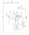
- Figure 1 shows a display system 48 containing a spatial light modulator with a linear array 85 of individually operable devices.
- Light is emitted from a source 70 and conditioned by a pair of lenses 72 and 74 before hitting a turning mirror 82 and illuminating the linear array 85.
- the display system of Fig. 1 forms an entire flicker-free two-dimensional scene on the screen 90 from a one-dimensional linear array modulator.
- the devices of the linear array 85 should therefore be capable of rapidly modulating incident light to produce multiple lines of pixels with gray levels.
- Electromechanical grating devices are the only welldeveloped spatial and temporal light modulators that, at the present time, can provide the required response times at low cost.
- the preferred modulators are either the conformal Grating ElectroMechanical System (GEMS) devices made by Eastman Kodak Company (see U.S. Patent No. 6,307,663, entitled “Spatial Light Modulator With Conformal Grating Device,” by Kowarz, October 23, 2001 and European Patent Application No. 01200128.5, entitled, “Method For Manufacturing A Mechanical Conformal Grating Device,” by Kowarz, et al., filed January 15, 2001); or the Grating Light Valves (GLV) made by Silicon Light Machines, disclosed in U.S. Patent No. 5,982,553, entitled, "Display Device Incorporating One-Dimensional Grating Light-Valve Array,” by Bloom et al., November 9, 1999.
- GEMS Conformal Grating ElectroMechanical System
- the linear array 85 contains conformal GEMS devices.
- display system 48 based on scanning linear arrays of conformal GEMS devices can be found in European Patent Application No. 01203551.5, " Electromechanical Grating Display System with Spatially Separate Light Beams," filed Sept. 19, 2001 by Kowarz, Brazas and Phalen.
- the controller 80 selectively activates the linear array 85 to obtain the desired pixel pattern for a given line of a two-dimensional scene. If a particular conformal GEMS device is not actuated, it reflects the incident light beam primarily into the 0th order light beam, which is directed back towards the source 70 by the turning mirror 82. If the device is actuated, it diffracts the incident light beams primarily into +2 nd ,+1 st , -1 st and -2 nd order light beams. These diffracted beams pass around the turning mirror 82 and are projected on the screen 90 by the projection lens system 75. The scanning mirror 77 sweeps the line image across the screen 90 to form the two-dimensional scene. The controller 80 provides synchronization between the sweep of the scanning mirror 77 and the data stream that provides the scene content.
- Figure 2 depicts a linear array 85 of conformal GEMS devices illuminated by a line of light 88.
- Figure 3 is a view facing the screen 90 showing the formation of the two-dimensional scene.
- HDTV resolution is obtained by scanning the image of the linear array 85 of 1080 conformal GEMS devices to generate 1920 sequential lines, thereby producing a scene with 1080 by 1920 pixels.
- the projection display system of Fig. 1 generates gray levels in the scene from code values in the data stream. Gray levels are obtained by using a look-up-table (LUT) to determine the required actuation voltage waveform for the devices of the linear array 85 based on the code value in the data stream.
- LUT look-up-table
- the LUT provides conversion between code values in the data stream and pulse-width modulated voltage pulses appropriate for actuating the devices.
- calibration of non-uniformities is possible if the LUT also allows a different correspondence between code values and gray levels for each of the devices of the linear array 85.
- FIG. 4A is a rendition of a photograph taken from a prototype projection display system with an uncalibrated flat field projected on a screen 90.
- This prototype system contains a linear array with 256 conformal GEMS devices.
- the uncalibrated flat field is generated by sending a data stream to the controller 80 with equal code values for each device on the linear array 85.
- the two-dimensional scene is formed by reimaging the non-zero diffracted orders of the linear array onto the screen 90 and using a galvanometer to sweep the line image across the screen 90.
- Parallel horizontal banding artifacts are clearly visible in the uncalibrated flat field along the scan direction.
- the bands are generated by the vertical non-uniformity that is present in the line image of the uncalibrated linear array.
- an image sensor 50 is added to the display system of Fig. 1.
- the controller 80 turns on the linear array 85 so that, initially, an uncalibrated flat field scene is projected on the screen 90.
- the image sensor 50 is used to capture an image of the uncalibrated flat field.
- the image sensor is a two-dimensional area array of light sensitive detectors incorporated into a digital camera.
- a precise estimate of the required correction factors requires an image sensor with a resolution along the device axis (vertical axis in Figs. 3, 4A and 4B) larger than the number of devices on the linear array 85.
- the image intensity data from the image sensor 50 is processed by the controller 80 to generate the appropriate correction factors for each device on the linear array 85. These correction factors are used to modify the LUT for converting code values in the data stream to actuation voltage waveforms for each device, thereby adjusting the gray levels. If necessary, the calibration steps can be repeated to optimize the uniformity of the flat field scene. This calibration process can be performed for additional gray levels of the flat field scene to assure uniformity throughout the gray scale needed for image display.
- Fig. 4B is a rendition of a photograph of the calibrated flat field scene (same system as Fig. 4A) after repeating the above calibration procedure several times.
- the horizontal banding visible in Fig. 4A is eliminated by calibration.
- the conformal GEMS array in this system produces gray levels through pulse width modulation. A particular gray level is produced by actuating the devices for a certain portion of the line time used to generate a vertical line of pixels.
- the correction factors are used to modify the LUT assignment for each device of the linear array between input code values and the pulse width of the actuation voltages.
- Calibration requires processing the image intensity data of the flat field to obtain a correction factor for each device of the linear array 85.
- One scheme for generating these correction factors is to average the image intensity data along the horizontal scan direction, with correction for any known skew or distortion created by the display system, camera system, or viewing conditions.
- the horizontal averaging reduces the two-dimensional image intensity data to a one-dimensional array of values corresponding to the average horizontal intensity.
- the averaging process improves signal-to-noise ratio for determining the appropriate correction factor. Noise from several different sources can be suppressed in this manner, including speckle in the projected image, local non-uniformity in the screen, and noise in the image sensor.
- the one-dimensional data set needs to be resampled to obtain a correction factor for each device of the linear array 85.
- the above embodiment overcomes several limitations of the prior art relating to the calibration of a display system with a linear array modulator: 1) it provides a high signal-to-noise ratio for calibrating even low intensity gray levels; 2) it performs calibration on the entire flat field scene simultaneously, thereby avoiding any non-linear effects between adjacent pixels; and 3) it directly calibrates the scene on the screen as viewed by the audience.
- Figure 5 illustrates an alternate embodiment in which the calibration image is formed internally within the display system 92.
- a beam splitter plate 56 is used to redirect a small portion of the diffracted light 73 through an image-forming lens 54 that produces an image for calibration directly on the image sensor 52.
- the image sensor 52 in Fig. 5 is preferably an area array of light sensitive sensors that simultaneously captures the entire image intensity data for calibration.
- a linear array of sensors with timesequential readout can be used to replace an area array of sensors.
- Figure 6 illustrates implementation of a display system 93 that produces RGB simultaneously.
- the red, green and blue channels each have their own light sources (70r, 70g, and 70b), lenses (72r, 72g, 72b, 74r, 74g, and 74b), turning mirrors (82r, 82g, and 82b) and linear arrays of light modulating devices (85r, 85g, and 85b).
- a color combining cube 100 is used to direct the red, green and blue outputs through the projection lens system 75 and onto the screen 90.
- the image sensor 50 is used to capture the image intensity data needed to generate the correction factors required for uniformity calibration of each of the three colors. For a monochrome image sensor 50, the three colors are calibrated one at a time.
- the calibration may be performed simultaneously for all three colors.
- the correction factors are used to modify the LUT assignment of the gray levels for each of the three linear arrays (85r, 85g, and 85b).
- the image intensity data can also be used to adjust the LUT assignments of the red, green and blue images to obtain a desired color balance.
- the image sensor 50 can be used to capture offset factors for calibration of pixel registration along the horizontal direction.
- an offset test pattern preferably consisting of vertical lines with high spatial frequency, is projected on the screen.
- the offset factors are determined by comparing the relative alignment of the three RGB images captured by the image sensor 50.
- Correction then involves a timing delay or advance between the data streams of the three linear arrays 85r, 85g, and 85b. The correction eliminates horizontal misalignment between the red, green and blue pixels on the screen 90.
- the purpose of the uniformity calibration process used in the projection display systems of Figs. 1, 5, and 6 is modification of the gray scale LUT used to convert code values in the data stream to actuation voltage waveforms for the modulating devices on the linear array 85.
- the calibration process assures that a data stream with equal code values for each modulating device will produce a uniform flat field scene on the screen 90 and that a range of code values will produce the desired range of gray levels.
- a method for calibrating a projection display having a scanned linear array modulator involves several operating steps. To start the calibration, operation 705 initializes the gray scale LUT. The appropriate initial values depend on the particular type of linear array modulator in the projection display.
- operation 710 a flat field scene is displayed on the screen.
- operation 720 causes image intensity data to be captured from the nominally flat field scene.
- the correction factors needed to generate a uniform flat field scene are calculated by appropriately processing the two-dimensional image intensity data. For example, in operations 730 and 740, this data processing is accomplished by averaging the image intensity data along the scan direction and determining the required correction factors for the gray scale LUT from the scan-averaged data. A re-sampling of the scan-averaged image intensity data may also be required (not shown).
- the subsequent operation 750 determines whether the flat field scene is sufficiently well calibrated. A uniformity metric is needed for this decision, such as the standard deviation of the newly calculated correction factors. If the standard deviation is below a certain threshold, the calibration procedure is terminated. Otherwise, operation 760 modifies the gray scale LUT using the correction factors and operations 710-750 are repeated. The calibration process is iterated until the flat field scene is sufficiently uniform as determined by the uniformity metric.
- FIG. 8 shows an alternative method for calibrating a projection display containing a scanned linear array modulator. Unlike the previous method, this approach does not require projection of a flat field scene. It can also be applied during the projection of scenes with real image content.
- the gray scale LUT is first initialized by operation 805.
- a data stream, continuously fed into the display system (operation 807), is used for two purposes: to display scenes on the screen (operation 810) and to provide a reference for calculating correction factors (operation 870).
- the scenes may contain images designed specifically for uniformity calibration or may contain ordinary motion images for display to a viewing audience.
- Operations 820 and 830 cause image intensity data to be captured and averaged along the scan direction. At the same time, operation 870 calculates the average expected intensity from the data stream.
- operation 840 compares the scan-averaged image intensity data to the average expected intensity.
- the standard deviation of the correction factors, or another suitable metric, is used by operation 850 to determine whether the gray scale LUT should be adjusted by performing operation 860. The method can be iterated as needed.
Landscapes
- Engineering & Computer Science (AREA)
- Multimedia (AREA)
- Signal Processing (AREA)
- Physics & Mathematics (AREA)
- Optics & Photonics (AREA)
- Health & Medical Sciences (AREA)
- Biomedical Technology (AREA)
- General Health & Medical Sciences (AREA)
- Control Of Indicators Other Than Cathode Ray Tubes (AREA)
- Projection Apparatus (AREA)
- Controls And Circuits For Display Device (AREA)
Applications Claiming Priority (2)
| Application Number | Priority Date | Filing Date | Title |
|---|---|---|---|
| US37954 | 2001-12-21 | ||
| US10/037,954 US6611380B2 (en) | 2001-12-21 | 2001-12-21 | System and method for calibration of display system with linear array modulator |
Publications (2)
| Publication Number | Publication Date |
|---|---|
| EP1322123A2 true EP1322123A2 (fr) | 2003-06-25 |
| EP1322123A3 EP1322123A3 (fr) | 2003-09-10 |
Family
ID=21897256
Family Applications (1)
| Application Number | Title | Priority Date | Filing Date |
|---|---|---|---|
| EP02080194A Withdrawn EP1322123A3 (fr) | 2001-12-21 | 2002-12-09 | Système et méthode pour la calibration d'un système d'afficheur utilisant un modulateur à reseau linéaire |
Country Status (4)
| Country | Link |
|---|---|
| US (1) | US6611380B2 (fr) |
| EP (1) | EP1322123A3 (fr) |
| JP (1) | JP4002504B2 (fr) |
| TW (1) | TWI240575B (fr) |
Cited By (21)
| Publication number | Priority date | Publication date | Assignee | Title |
|---|---|---|---|---|
| WO2005009048A1 (fr) * | 2003-07-17 | 2005-01-27 | Koninklijke Philips Electronics N.V. | Systeme d'imagerie optique avec agencement de modulateurs de lasers ou de diodes electroluminescentes monte sur une pellicule |
| WO2005015904A1 (fr) * | 2003-08-06 | 2005-02-17 | Mitsubishi Denki Kabushiki Kaisha | Procede et systeme pour determiner la correspondance entre les emplacements sur des surfaces d'affichage, presentant une forme arbitraire, et des pixels dans l'image de sortie d'un projecteur |
| WO2007081215A1 (fr) * | 2005-12-07 | 2007-07-19 | Polight As | Systeme d'affichage de projection a balayage lineaire comprenant un modulateur de lumiere a deux reseaux de pixels |
| WO2010151310A1 (fr) * | 2009-06-25 | 2010-12-29 | Eastman Kodak Company | Commande d'intensité de lumière hiérarchique dans un projecteur de lumière |
| US8045024B2 (en) | 2009-04-15 | 2011-10-25 | Omnivision Technologies, Inc. | Producing full-color image with reduced motion blur |
| US8068153B2 (en) | 2009-03-27 | 2011-11-29 | Omnivision Technologies, Inc. | Producing full-color image using CFA image |
| US8119435B2 (en) | 2008-07-09 | 2012-02-21 | Omnivision Technologies, Inc. | Wafer level processing for backside illuminated image sensors |
| US8125546B2 (en) | 2009-06-05 | 2012-02-28 | Omnivision Technologies, Inc. | Color filter array pattern having four-channels |
| US8139130B2 (en) | 2005-07-28 | 2012-03-20 | Omnivision Technologies, Inc. | Image sensor with improved light sensitivity |
| US8142021B2 (en) | 2009-06-25 | 2012-03-27 | Eastman Kodak Company | Dump path light intensity sensing in light projector |
| US8194296B2 (en) | 2006-05-22 | 2012-06-05 | Omnivision Technologies, Inc. | Image sensor with improved light sensitivity |
| US8203633B2 (en) | 2009-05-27 | 2012-06-19 | Omnivision Technologies, Inc. | Four-channel color filter array pattern |
| US8220938B2 (en) | 2009-06-25 | 2012-07-17 | Eastman Kodak Company | Image path light intensity sensing during a blanking period between a left-eye light beam and a right-eye light beam in a stereoscopic light projector |
| US8224082B2 (en) | 2009-03-10 | 2012-07-17 | Omnivision Technologies, Inc. | CFA image with synthetic panchromatic image |
| US8237831B2 (en) | 2009-05-28 | 2012-08-07 | Omnivision Technologies, Inc. | Four-channel color filter array interpolation |
| US8237777B2 (en) | 2009-06-25 | 2012-08-07 | Eastman Kodak Company | Stereoscopic image intensity balancing in light projector |
| US8253832B2 (en) | 2009-06-09 | 2012-08-28 | Omnivision Technologies, Inc. | Interpolation for four-channel color filter array |
| US8274715B2 (en) | 2005-07-28 | 2012-09-25 | Omnivision Technologies, Inc. | Processing color and panchromatic pixels |
| US8416339B2 (en) | 2006-10-04 | 2013-04-09 | Omni Vision Technologies, Inc. | Providing multiple video signals from single sensor |
| WO2014094827A1 (fr) * | 2012-12-18 | 2014-06-26 | Lemoptix Sa | Circuit de commande de laser et procédé de commande de laser |
| CN114419170A (zh) * | 2022-03-30 | 2022-04-29 | 杭州灵西机器人智能科技有限公司 | 线阵相机和面阵相机的联合标定方法、装置和介质 |
Families Citing this family (22)
| Publication number | Priority date | Publication date | Assignee | Title |
|---|---|---|---|---|
| US6976629B2 (en) * | 2002-03-20 | 2005-12-20 | Symbol Technologies, Inc. | Image capture system and method |
| JP2004157522A (ja) * | 2002-10-17 | 2004-06-03 | Sony Corp | 画像生成装置、画像表示装置、画像表示方法、及び光変調素子調整装置 |
| US6807010B2 (en) * | 2002-11-13 | 2004-10-19 | Eastman Kodak Company | Projection display apparatus having both incoherent and laser light sources |
| US6904376B2 (en) * | 2003-08-28 | 2005-06-07 | Chris Chen | Calibration device for a 2D image display module |
| US6984039B2 (en) * | 2003-12-01 | 2006-01-10 | Eastman Kodak Company | Laser projector having silhouette blanking for objects in the output light path |
| JP4507616B2 (ja) * | 2004-02-04 | 2010-07-21 | セイコーエプソン株式会社 | 投射型表示装置、画像出力機器および投射型表示装置の制御方法 |
| JP2005345904A (ja) * | 2004-06-04 | 2005-12-15 | Sony Corp | 画像生成装置 |
| JP2006323035A (ja) * | 2005-05-18 | 2006-11-30 | Sony Corp | 表示装置および表示方法 |
| US7411722B2 (en) * | 2005-08-24 | 2008-08-12 | Eastman Kodak Company | Display system incorporating bilinear electromechanical grating device |
| KR100819872B1 (ko) | 2006-05-17 | 2008-04-07 | 삼성전기주식회사 | 광 변조기 캘리브레이션 장치 |
| KR100755679B1 (ko) * | 2006-06-08 | 2007-09-05 | 삼성전기주식회사 | 광변조기에서의 변위차를 보상하기 위한 라인 프로파일을생성하는 방법 및 장치 |
| KR100861344B1 (ko) * | 2006-09-01 | 2008-10-01 | 삼성전기주식회사 | 광변조기를 포함하는 디스플레이 장치 및 영상 제어 방법 |
| US8749463B2 (en) * | 2007-01-19 | 2014-06-10 | Hamamatsu Photonics K.K. | Phase-modulating apparatus |
| US8994757B2 (en) | 2007-03-15 | 2015-03-31 | Scalable Display Technologies, Inc. | System and method for providing improved display quality by display adjustment and image processing using optical feedback |
| US7782521B2 (en) * | 2007-05-31 | 2010-08-24 | Texas Instruments Incorporated | System and method for displaying images |
| KR20090032171A (ko) * | 2007-09-27 | 2009-04-01 | 삼성전기주식회사 | 디스플레이 장치 및 빔 정렬 보상 방법 |
| JP5424676B2 (ja) * | 2009-03-13 | 2014-02-26 | キヤノン株式会社 | 画像処理装置 |
| EP2842330B1 (fr) | 2012-04-13 | 2018-08-29 | Red.Com, Llc | Système de projecteur vidéo |
| US9025086B2 (en) | 2012-04-13 | 2015-05-05 | Red.Com, Inc. | Video projector system |
| CN110891169B (zh) * | 2018-08-19 | 2021-07-09 | 安徽省东超科技有限公司 | 一种基于光泳捕获的可交互体三维显示装置及其控制方法 |
| ES3005120T3 (en) | 2020-01-30 | 2025-03-13 | Dolby Laboratories Licensing Corp | Projection system and method for uniformity correction |
| TWI900906B (zh) * | 2023-03-17 | 2025-10-11 | 財團法人工業技術研究院 | 陣列式物鏡模組及光學干涉顯微系統 |
Family Cites Families (11)
| Publication number | Priority date | Publication date | Assignee | Title |
|---|---|---|---|---|
| US4868668A (en) | 1986-08-21 | 1989-09-19 | Electrohome Limited | System and method for image adjustment in an optical projection system |
| GB9008031D0 (en) | 1990-04-09 | 1990-06-06 | Rank Brimar Ltd | Projection systems |
| US5793441A (en) * | 1995-06-07 | 1998-08-11 | Hughes-Jvc Technology Corporation | Method and apparatus for measuring illumination uniformity of a liquid crystal light valve projector |
| US5633691A (en) * | 1995-06-07 | 1997-05-27 | Nview Corporation | Stylus position sensing and digital camera with a digital micromirror device |
| GB2312121A (en) * | 1996-04-13 | 1997-10-15 | Thomson Multimedia Sa | LCD television projector with lamp aging compensation |
| US5982553A (en) | 1997-03-20 | 1999-11-09 | Silicon Light Machines | Display device incorporating one-dimensional grating light-valve array |
| US6307663B1 (en) | 2000-01-26 | 2001-10-23 | Eastman Kodak Company | Spatial light modulator with conformal grating device |
| US6411425B1 (en) * | 2000-09-27 | 2002-06-25 | Eastman Kodak Company | Electromechanical grating display system with spatially separated light beams |
| US6323984B1 (en) * | 2000-10-11 | 2001-11-27 | Silicon Light Machines | Method and apparatus for reducing laser speckle |
| US6476848B2 (en) * | 2000-12-21 | 2002-11-05 | Eastman Kodak Company | Electromechanical grating display system with segmented waveplate |
| US6384959B1 (en) * | 2001-01-09 | 2002-05-07 | Eastman Kodak Company | Optical data modulation system with self-damped electromechanical conformal grating |
-
2001
- 2001-12-21 US US10/037,954 patent/US6611380B2/en not_active Expired - Lifetime
-
2002
- 2002-11-04 TW TW091132483A patent/TWI240575B/zh not_active IP Right Cessation
- 2002-12-09 EP EP02080194A patent/EP1322123A3/fr not_active Withdrawn
- 2002-12-12 JP JP2002360291A patent/JP4002504B2/ja not_active Expired - Fee Related
Cited By (27)
| Publication number | Priority date | Publication date | Assignee | Title |
|---|---|---|---|---|
| WO2005009048A1 (fr) * | 2003-07-17 | 2005-01-27 | Koninklijke Philips Electronics N.V. | Systeme d'imagerie optique avec agencement de modulateurs de lasers ou de diodes electroluminescentes monte sur une pellicule |
| WO2005015904A1 (fr) * | 2003-08-06 | 2005-02-17 | Mitsubishi Denki Kabushiki Kaisha | Procede et systeme pour determiner la correspondance entre les emplacements sur des surfaces d'affichage, presentant une forme arbitraire, et des pixels dans l'image de sortie d'un projecteur |
| US7001023B2 (en) | 2003-08-06 | 2006-02-21 | Mitsubishi Electric Research Laboratories, Inc. | Method and system for calibrating projectors to arbitrarily shaped surfaces with discrete optical sensors mounted at the surfaces |
| US8711452B2 (en) | 2005-07-28 | 2014-04-29 | Omnivision Technologies, Inc. | Processing color and panchromatic pixels |
| US8330839B2 (en) | 2005-07-28 | 2012-12-11 | Omnivision Technologies, Inc. | Image sensor with improved light sensitivity |
| US8139130B2 (en) | 2005-07-28 | 2012-03-20 | Omnivision Technologies, Inc. | Image sensor with improved light sensitivity |
| US8274715B2 (en) | 2005-07-28 | 2012-09-25 | Omnivision Technologies, Inc. | Processing color and panchromatic pixels |
| WO2007081215A1 (fr) * | 2005-12-07 | 2007-07-19 | Polight As | Systeme d'affichage de projection a balayage lineaire comprenant un modulateur de lumiere a deux reseaux de pixels |
| US8194296B2 (en) | 2006-05-22 | 2012-06-05 | Omnivision Technologies, Inc. | Image sensor with improved light sensitivity |
| US8416339B2 (en) | 2006-10-04 | 2013-04-09 | Omni Vision Technologies, Inc. | Providing multiple video signals from single sensor |
| US8119435B2 (en) | 2008-07-09 | 2012-02-21 | Omnivision Technologies, Inc. | Wafer level processing for backside illuminated image sensors |
| US8224082B2 (en) | 2009-03-10 | 2012-07-17 | Omnivision Technologies, Inc. | CFA image with synthetic panchromatic image |
| US8068153B2 (en) | 2009-03-27 | 2011-11-29 | Omnivision Technologies, Inc. | Producing full-color image using CFA image |
| US8045024B2 (en) | 2009-04-15 | 2011-10-25 | Omnivision Technologies, Inc. | Producing full-color image with reduced motion blur |
| US8203633B2 (en) | 2009-05-27 | 2012-06-19 | Omnivision Technologies, Inc. | Four-channel color filter array pattern |
| US8237831B2 (en) | 2009-05-28 | 2012-08-07 | Omnivision Technologies, Inc. | Four-channel color filter array interpolation |
| US8125546B2 (en) | 2009-06-05 | 2012-02-28 | Omnivision Technologies, Inc. | Color filter array pattern having four-channels |
| US8253832B2 (en) | 2009-06-09 | 2012-08-28 | Omnivision Technologies, Inc. | Interpolation for four-channel color filter array |
| US8142021B2 (en) | 2009-06-25 | 2012-03-27 | Eastman Kodak Company | Dump path light intensity sensing in light projector |
| US8237777B2 (en) | 2009-06-25 | 2012-08-07 | Eastman Kodak Company | Stereoscopic image intensity balancing in light projector |
| US8162483B2 (en) | 2009-06-25 | 2012-04-24 | Eastman Kodak Company | Hierarchical light intensity control in light projector |
| US8220938B2 (en) | 2009-06-25 | 2012-07-17 | Eastman Kodak Company | Image path light intensity sensing during a blanking period between a left-eye light beam and a right-eye light beam in a stereoscopic light projector |
| WO2010151310A1 (fr) * | 2009-06-25 | 2010-12-29 | Eastman Kodak Company | Commande d'intensité de lumière hiérarchique dans un projecteur de lumière |
| WO2014094827A1 (fr) * | 2012-12-18 | 2014-06-26 | Lemoptix Sa | Circuit de commande de laser et procédé de commande de laser |
| US9496682B2 (en) | 2012-12-18 | 2016-11-15 | Intel Corporation | Laser driver and method of operating a laser |
| CN114419170A (zh) * | 2022-03-30 | 2022-04-29 | 杭州灵西机器人智能科技有限公司 | 线阵相机和面阵相机的联合标定方法、装置和介质 |
| CN114419170B (zh) * | 2022-03-30 | 2022-07-15 | 杭州灵西机器人智能科技有限公司 | 线阵相机和面阵相机的联合标定方法、装置和介质 |
Also Published As
| Publication number | Publication date |
|---|---|
| JP4002504B2 (ja) | 2007-11-07 |
| US20030117711A1 (en) | 2003-06-26 |
| TW200301653A (en) | 2003-07-01 |
| US6611380B2 (en) | 2003-08-26 |
| TWI240575B (en) | 2005-09-21 |
| EP1322123A3 (fr) | 2003-09-10 |
| JP2003195417A (ja) | 2003-07-09 |
Similar Documents
| Publication | Publication Date | Title |
|---|---|---|
| US6611380B2 (en) | System and method for calibration of display system with linear array modulator | |
| US6801365B2 (en) | Projection type image display system and color correction method thereof | |
| US5369433A (en) | Recording video signals on cinematographic film using a deformable mirror device | |
| US6552855B1 (en) | Image-forming system with enhanced gray levels | |
| JP3100628B2 (ja) | 投写システム | |
| US6736514B2 (en) | Imaging apparatus for increased color gamut using dual spatial light modulators | |
| US20050093982A1 (en) | Image pickup apparatus and method, image processing apparatus and method, image display system, recording medium and program | |
| JP2001265275A (ja) | 画像表示装置 | |
| JPH09326981A (ja) | 画像投影システム | |
| JP2004507987A (ja) | 光学関数生成器を使用するシームレスなタイル式ディスプレイのための電子較正 | |
| US9621862B2 (en) | Projector and method of controlling projector | |
| WO2002093913A1 (fr) | Systeme et procede pour capturer, transmettre et afficher une image | |
| WO2002093914A1 (fr) | Systeme et procede pour produire une image a l'aide d'un ecran utilisant des sources lumineuses d'effacement (inactivees) et de formation d'image (activees) | |
| US20030085857A1 (en) | Display apparatus box using a spatial light modulator | |
| JP2002223454A (ja) | 投射型画像表示装置 | |
| US7172288B2 (en) | Display device including a spatial light modulator with plural image regions | |
| US6837582B2 (en) | Image adjuster of projector and image adjusting method of image display | |
| CN114582260B (zh) | 颜色矫正方法及光纤扫描成像系统 | |
| JP2003018502A (ja) | 投射型表示装置 | |
| JP2006072221A (ja) | 画像生成装置及び画像投射装置 | |
| Agostinelli et al. | Gems: A simple light modulator for high-performance laser projection display | |
| WO2022052921A1 (fr) | Système de projection et procédé de correction d'image projetée | |
| JP2005099478A (ja) | スペクトル解析機能をもつプロジェクタ | |
| WO2021038692A1 (fr) | Dispositif d'imagerie, procédé d'imagerie, et programme de traitement vidéo | |
| JP2006295253A (ja) | 視覚情報処理装置及びその視覚情報処理方法 |
Legal Events
| Date | Code | Title | Description |
|---|---|---|---|
| PUAI | Public reference made under article 153(3) epc to a published international application that has entered the european phase |
Free format text: ORIGINAL CODE: 0009012 |
|
| AK | Designated contracting states |
Designated state(s): AT BE BG CH CY CZ DE DK EE ES FI FR GB GR IE IT LI LU MC NL PT SE SI SK TR |
|
| AX | Request for extension of the european patent |
Extension state: AL LT LV MK RO |
|
| PUAL | Search report despatched |
Free format text: ORIGINAL CODE: 0009013 |
|
| AK | Designated contracting states |
Kind code of ref document: A3 Designated state(s): AT BE BG CH CY CZ DE DK EE ES FI FR GB GR IE IT LI LU MC NL PT SE SI SK TR |
|
| AX | Request for extension of the european patent |
Extension state: AL LT LV MK RO |
|
| RIC1 | Information provided on ipc code assigned before grant |
Ipc: 7H 04N 5/74 B Ipc: 7H 04N 17/04 A |
|
| AKX | Designation fees paid | ||
| 17P | Request for examination filed |
Effective date: 20040503 |
|
| RBV | Designated contracting states (corrected) |
Designated state(s): DE GB |
|
| REG | Reference to a national code |
Ref country code: DE Ref legal event code: 8566 |
|
| 17Q | First examination report despatched |
Effective date: 20091106 |
|
| STAA | Information on the status of an ep patent application or granted ep patent |
Free format text: STATUS: THE APPLICATION IS DEEMED TO BE WITHDRAWN |
|
| 18D | Application deemed to be withdrawn |
Effective date: 20131127 |