EP1322885B1 - Vorrichtung zum greifen eines rohres oder einer stange - Google Patents
Vorrichtung zum greifen eines rohres oder einer stange Download PDFInfo
- Publication number
- EP1322885B1 EP1322885B1 EP01974451A EP01974451A EP1322885B1 EP 1322885 B1 EP1322885 B1 EP 1322885B1 EP 01974451 A EP01974451 A EP 01974451A EP 01974451 A EP01974451 A EP 01974451A EP 1322885 B1 EP1322885 B1 EP 1322885B1
- Authority
- EP
- European Patent Office
- Prior art keywords
- bar
- pipe
- external wall
- cage
- inserted pipe
- Prior art date
- Legal status (The legal status is an assumption and is not a legal conclusion. Google has not performed a legal analysis and makes no representation as to the accuracy of the status listed.)
- Expired - Lifetime
Links
- 239000012530 fluid Substances 0.000 claims abstract description 12
- 230000037431 insertion Effects 0.000 claims abstract description 4
- 238000003780 insertion Methods 0.000 claims abstract description 4
- 238000001125 extrusion Methods 0.000 claims description 6
- 229910000760 Hardened steel Inorganic materials 0.000 claims description 3
- 238000007789 sealing Methods 0.000 claims description 2
- 229910001369 Brass Inorganic materials 0.000 description 2
- 229910000831 Steel Inorganic materials 0.000 description 2
- 239000010951 brass Substances 0.000 description 2
- 230000000717 retained effect Effects 0.000 description 2
- 239000010959 steel Substances 0.000 description 2
- 230000015572 biosynthetic process Effects 0.000 description 1
- 239000000463 material Substances 0.000 description 1
- 239000002184 metal Substances 0.000 description 1
- 229920003052 natural elastomer Polymers 0.000 description 1
- 229920001194 natural rubber Polymers 0.000 description 1
- 239000004810 polytetrafluoroethylene Substances 0.000 description 1
- 229920001343 polytetrafluoroethylene Polymers 0.000 description 1
- 229920003051 synthetic elastomer Polymers 0.000 description 1
- 239000005061 synthetic rubber Substances 0.000 description 1
Images
Classifications
-
- F—MECHANICAL ENGINEERING; LIGHTING; HEATING; WEAPONS; BLASTING
- F16—ENGINEERING ELEMENTS AND UNITS; GENERAL MEASURES FOR PRODUCING AND MAINTAINING EFFECTIVE FUNCTIONING OF MACHINES OR INSTALLATIONS; THERMAL INSULATION IN GENERAL
- F16L—PIPES; JOINTS OR FITTINGS FOR PIPES; SUPPORTS FOR PIPES, CABLES OR PROTECTIVE TUBING; MEANS FOR THERMAL INSULATION IN GENERAL
- F16L37/00—Couplings of the quick-acting type
- F16L37/08—Couplings of the quick-acting type in which the connection between abutting or axially overlapping ends is maintained by locking members
- F16L37/084—Couplings of the quick-acting type in which the connection between abutting or axially overlapping ends is maintained by locking members combined with automatic locking
- F16L37/092—Couplings of the quick-acting type in which the connection between abutting or axially overlapping ends is maintained by locking members combined with automatic locking by means of elements wedged between the pipe and the frusto-conical surface of the body of the connector
- F16L37/0927—Couplings of the quick-acting type in which the connection between abutting or axially overlapping ends is maintained by locking members combined with automatic locking by means of elements wedged between the pipe and the frusto-conical surface of the body of the connector the wedge element being axially displaceable for releasing the coupling
-
- F—MECHANICAL ENGINEERING; LIGHTING; HEATING; WEAPONS; BLASTING
- F16—ENGINEERING ELEMENTS AND UNITS; GENERAL MEASURES FOR PRODUCING AND MAINTAINING EFFECTIVE FUNCTIONING OF MACHINES OR INSTALLATIONS; THERMAL INSULATION IN GENERAL
- F16L—PIPES; JOINTS OR FITTINGS FOR PIPES; SUPPORTS FOR PIPES, CABLES OR PROTECTIVE TUBING; MEANS FOR THERMAL INSULATION IN GENERAL
- F16L37/00—Couplings of the quick-acting type
- F16L37/22—Couplings of the quick-acting type in which the connection is maintained by means of balls, rollers or helical springs under radial pressure between the parts
- F16L37/23—Couplings of the quick-acting type in which the connection is maintained by means of balls, rollers or helical springs under radial pressure between the parts by means of balls
Definitions
- THIS INVENTION concerns a device for gripping the external wall surface of a pipe or bar and particularly, though not exclusively, to a connector adapted to receive and retain a pipe end for fluid connection to another pipe end or to a supply outlet.
- An object of the present invention is to provide a gripping device such as a pipe connector wherein the aforementioned disadvantage is substantially avoided.
- a device for gripping the external wall surface of a pipe or bar comprising a tubular body having at least one end open for insertion of a pipe or bar, a cage within the tubular body with balls or rollers cooperating with a first tapered internal wall part of the body, and resilient means to push the cage in an axial direction to cause the balls or rollers to grip the external wall surface of an inserted pipe or bar; characterised by a compressible member located within the body and cooperating with a second tapered internal wall part of the body and movable relative thereto when increased fluid pressure is present within the body thus also to grip the external wall surface of the inserted pipe or bar.
- the compressible member has a contact surface adapted to make substantially full circumferential contact with the external wall surface of the inserted pipe or bar.
- the device may include a sealing ring adapted to form a seal between the internal wall of the body and the external wall surface of the inserted pipe or bar.
- the cage and the compressible member may have respective cooperating faces for simultaneous axial movement within the body.
- the compressible member may be a circumferentially split ferrule.
- the body may comprise axially aligned separate body parts each threadedly engageable with a co-axial spring retaining member housed within the body.
- the body may contain an anti-extrusion ring axially aligned with the circumferentially split ferrule, and a tapered ring located between the anti-extrusion ring and the circumferentially split ferrule.
- the body may include an annular shoulder against wh ich an end of the inserted pipe or bar may be located.
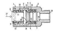
- the connector comprises a first tubular body part 1 having a first tapered internal wall part 11. Threadedly engaged within one end of the body part 1 is a spring retaining member 3. An external thread of the retaining member 3 receives a second tubular body part 2.
- a ball cage 8 is located co-axially within the body part 1 and includes an outwardly directed circumferential flange 12 which, together with an inwardly directed flange 13 on the spring retaining member 3, retains a coil spring 10 whereby the cage 8 is pushed in an axial direction to cause a number of ball bearings 9 to ride radially inwardly on the first tapered internal wall part 11.
- the cage is retained within the body part 1 by engagement of the flange 12 with the wall part 11.
- the flange 13 of the spring retaining member 3 has a tapered internal face 14 against which is located a corresponding tapered external face of a circumferentially split ferrule 4 located within the body part 2 co-axially therewith.
- a metal ring 5 Abutting an end face 15 of the ferrule 4 axially remote from the cage 8 is a metal ring 5 having a tapered face 16 against which is located a corresponding tapered face of an anti-extrusion ring 6 preferably, though not exclusively, of PTFE.
- Axially displaced from the anti-extrusion ring 6 is an 'O' ring 7 which in use forms a pressure tight seal between the internal wall of the body part 2 and a pipe to be inserted into the connector as will be described.
- body part 1, ball cage 8, spring retainer 3 and spring 10 may be pre-assembled, as can the body part 2, the 'O' ring 7, the rings 5 and 6 and the split ferrule 4, whereupon joining of the two body parts forms the final assembly.
- the body parts 1 and 2 may be of steel or brass; the spring-retainer 3 may be of steel; the ball bearings 9 may be of hardened steel, the split ferrule 4 may be of hardened steel segments with elastomeric inserts, the 'O' ring 7 may be of natural or synthetic rubber; and the ring 5 may be of brass.
- a connecting device as described may be used in conjunction with pipes of a diameter up to 50mm with internal pressures in the region of 207 to 474 bar (3,000 to 6,000 psi), but is typically tested to a pressure in excess of 1379 bar (20,000 psi).
- the connector is used by inserting a pipe end in the direction of arrow 17 which causes the ball cage 8 to move against the spring 10 such that the ball bearings 9 ride along the external wall of the inserted pipe.
- An annular shoulder 18 preferably, though not essentially, forms an end stop for the pipe whereupon the pipe is retained by the pressure of spring 10 acting to cause ball bearings 9 to form a grip upon the external wall of the inserted pipe but with insufficient pressure to become embedded therein.
- the body part 2 has an end portion 19 which may be connected to another such connecting device or to a port for the transportation of pressurised fluid.
- circumferentially split ferrule 4 is clear of the ipe during initial insertion and only grips the external wall thereof when compressed by the tapered face 14 upon the application of an increased fluid pressure within the device.
- a further advantage of the present device is that it is the internal fluid pressure which provides the gripping action and no additional tools or the like are needed for tightening the device, unlike some types of pipe connector where relative rotation of the parts is needed to grip the pipe.
- the device is thus self-gripping with minimal linear slip of the pipe in use and considerably reduced deformation or surface damage to the pipe wall in view of the substantially full circumferential contact between the latter and the split ferrule.
- any further increase in internal fluid pressure serves only to cause the split ferrule 4 to grip the pipe more firmly.
- ferrule 4 is illustrated as having an internal toothed gripping surface, in some cases a smooth internal surface is sufficient.
- the connector Since the ball bearings do not excessively grip the pipe wall the connector is re-usable with, perhaps, the split ferrule 4 being the only part requiring replacement in some cases.
- the device may serve as a pipe or bar retaining device, pressurised fluid being introduced into the body part 2 such as to force the 'O' ring 7 and the rings 6 and 5 towards the split ferrule 4.
- the pressurised fluid may be introduced through a port in the wall of the body part 2 or, in the case of a pressurised pipe, by way of an aperture in the pipe wall.
Landscapes
- Engineering & Computer Science (AREA)
- General Engineering & Computer Science (AREA)
- Mechanical Engineering (AREA)
- Quick-Acting Or Multi-Walled Pipe Joints (AREA)
- Load-Engaging Elements For Cranes (AREA)
- Manipulator (AREA)
- Investigating Or Analyzing Materials By The Use Of Ultrasonic Waves (AREA)
- Containers And Plastic Fillers For Packaging (AREA)
- Pipe Accessories (AREA)
Claims (9)
- Vorrichtung zum Einspannen der äußeren Wandoberfläche eines Rohres oder einer Stange, mit einem rohrförmigen Körper (1, 2), der wenigstens ein Ende hat, das zum Einführen eines Rohres oder einer Stange offen ist, einem Käfig (8) mit Kugeln (9) oder Rollen, die mit einem ersten konisch zulaufenden inneren Wandteil (11) des Körpers zusammenwirken, und einer elastischen Einrichtung (10), vorzugsweise einer Feder (10), zum Drücken des Käfigs (8) in eine axiale Richtung, um zu bewirken, dass die Kugeln (9) oder die Rollen die äußere Wand eines eingeführten Rohres oder einer eingeführten Stange einspannen; gekennzeichnet durch ein kompressibles Teil (4), das innerhalb des Körpers (1, 2) angeordnet ist und mit einem zweiten konisch zulaufenden inneren Wandteil (14) des Körpers oder eines koaxialen Federhalteteils (3), das in dem Gehäuse (1, 2) untergebracht ist, zusammenwirkt und relativ dazu beweglich ist, wenn erhöhter Fluiddruck innerhalb des Körpers vorhanden ist, um so auch die äußere Wand des eingeführten Rohres oder der eingeführten Stange einzuspannen.
- Vorrichtung nach Anspruch 1, wobei das kompressible Teil (4) eine Kontaktoberfläche hat, die dafür ausgebildet ist, im Wesentlichen vollständigen umfangsmäßigen Kontakt mit der äußeren Wandoberfläche des eingeführten Rohres oder der eingeführten Stange herzustellen.
- Vorrichtung nach Anspruch 1 oder 2, mit einem Dichtring (7), der dafür ausgebildet ist, eine Dichtung zwischen der inneren Wand des Körpers (1, 2) und der äußeren Wandoberfläche des eingeführten Rohres oder der eingeführten Stange zu bilden.
- Vorrichtung nach einem der vorhergehenden Ansprüche, wobei der Käfig (8) und das kompressible Teil (4) zusammenwirkende Stirnflächen (20, 21) zur gleichzeitigen axialen Bewegung innerhalb des Körpers haben.
- Vorrichtung nach einem der vorhergehenden Ansprüche, wobei das kompressible Teil (4) ein umfangsmäßig geteilter Spannring ist.
- Vorrichtung nach Anspruch 5, wobei der umfangsmäßig geteilte Spannring gehärtete Stahlsegmente mit elastomeren Einsätzen aufweist.
- Vorrichtung nach einem der vorhergehenden Ansprüche, wobei der Körper (1, 2) axial ausgerichtete separate Körperteile aufweist, die jeweils mit einem koaxialen Federhalteteil (3), das in dem Körper untergebracht ist, in Gewindeeingriff bringbar sind.
- Vorrichtung nach Anspruch 5 oder 6, wobei der Körper (1, 2) einen Antiextrusionsring (6) enthält, der mit dem umfangsmäßig geteilten Spannring (4) axial ausgerichtet ist, und einen konisch zulaufenden Ring (5), der zwischen dem Antiextrusionsring (6) und dem umfangsmäßig geteilten Spannring (4) angeordnet ist.
- Vorrichtung nach einem der vorhergehenden Ansprüche, wobei der Körper (1, 2) eine ringförmige Schulter (18) aufweist, an die sich ein Ende des eingeführten Rohres oder der eingeführten Stange anlegen kann.
Applications Claiming Priority (3)
| Application Number | Priority Date | Filing Date | Title |
|---|---|---|---|
| GBGB0024278.4A GB0024278D0 (en) | 2000-10-04 | 2000-10-04 | A device for gripping a pipe or bar |
| GB0024278 | 2000-10-04 | ||
| PCT/GB2001/004411 WO2002029301A1 (en) | 2000-10-04 | 2001-10-04 | A device for gripping a pipe or bar |
Publications (2)
| Publication Number | Publication Date |
|---|---|
| EP1322885A1 EP1322885A1 (de) | 2003-07-02 |
| EP1322885B1 true EP1322885B1 (de) | 2005-06-22 |
Family
ID=9900652
Family Applications (1)
| Application Number | Title | Priority Date | Filing Date |
|---|---|---|---|
| EP01974451A Expired - Lifetime EP1322885B1 (de) | 2000-10-04 | 2001-10-04 | Vorrichtung zum greifen eines rohres oder einer stange |
Country Status (14)
| Country | Link |
|---|---|
| US (1) | US6991265B2 (de) |
| EP (1) | EP1322885B1 (de) |
| JP (1) | JP2004510934A (de) |
| AT (1) | ATE298406T1 (de) |
| AU (2) | AU2001293966B2 (de) |
| BR (1) | BR0114412A (de) |
| CA (1) | CA2423679A1 (de) |
| DE (1) | DE60111641T2 (de) |
| DK (1) | DK1322885T3 (de) |
| ES (1) | ES2242773T3 (de) |
| GB (1) | GB0024278D0 (de) |
| NO (1) | NO20031520L (de) |
| PT (1) | PT1322885E (de) |
| WO (1) | WO2002029301A1 (de) |
Families Citing this family (32)
| Publication number | Priority date | Publication date | Assignee | Title |
|---|---|---|---|---|
| GB0301895D0 (en) * | 2003-01-28 | 2003-02-26 | Bsw Ltd | A gripping tool |
| US7284772B2 (en) * | 2003-12-19 | 2007-10-23 | Alder Randall F | Coupling assembly |
| US7445050B2 (en) * | 2006-04-25 | 2008-11-04 | Canrig Drilling Technology Ltd. | Tubular running tool |
| US7552764B2 (en) * | 2007-01-04 | 2009-06-30 | Nabors Global Holdings, Ltd. | Tubular handling device |
| NO328491B1 (no) * | 2007-02-06 | 2010-03-01 | Raufoss Water & Gas As | Kobling |
| US8074711B2 (en) | 2008-06-26 | 2011-12-13 | Canrig Drilling Technology Ltd. | Tubular handling device and methods |
| US8720541B2 (en) | 2008-06-26 | 2014-05-13 | Canrig Drilling Technology Ltd. | Tubular handling device and methods |
| NL2002303C2 (nl) * | 2008-12-08 | 2010-06-10 | Henri Peteri Beheer Bv | Leidingconstructie voor een heetwaterkraan, alsmede een dergelijke kraan. |
| US7986572B2 (en) * | 2009-08-17 | 2011-07-26 | Magic Technologies, Inc. | Magnetic memory capable of minimizing gate voltage stress in unselected memory cells |
| US9052047B2 (en) * | 2010-06-03 | 2015-06-09 | Keith Covert | Quick connect coupler for glass container molding machine |
| US20120001418A1 (en) * | 2010-07-02 | 2012-01-05 | Michel Garcin | Connector |
| EP2627938B1 (de) | 2010-10-15 | 2018-09-05 | Swagelok Company | Schnell einrastendes leitungsendstück mit hülse |
| WO2012100019A1 (en) | 2011-01-21 | 2012-07-26 | 2M-Tek, Inc. | Tubular running device and method |
| US20130056976A1 (en) * | 2011-09-02 | 2013-03-07 | Sung-Hun Kim | One-touch pipe connection device |
| GB201117049D0 (en) | 2011-10-04 | 2011-11-16 | Ecolok Ltd | Method and apparatus for gripping |
| CA2928522C (en) * | 2013-10-24 | 2021-02-23 | Swagelok Company | Single action push to connect conduit fitting |
| CA2890494C (en) * | 2014-05-02 | 2023-08-01 | Sigma Electric Manufacturing Corporation | Connectors and methods for making and using the same |
| GB201415044D0 (en) * | 2014-08-26 | 2014-10-08 | Ftl Subsea Ltd | Clamp |
| CN104455814B (zh) * | 2014-11-14 | 2016-11-30 | 无锡乐华自动化科技有限公司 | 一种动态膨胀油管接头 |
| CN104534212B (zh) * | 2014-12-22 | 2017-02-22 | 林圣博 | 一种锁紧式快速接头 |
| EP3286476B1 (de) * | 2015-04-23 | 2019-10-02 | Swagelok Company | Steckverbindung für ein rohr |
| US10458582B2 (en) | 2015-04-23 | 2019-10-29 | Swagelok Company | Single action push to connect conduit fitting with colleting |
| US20170097036A1 (en) * | 2015-10-02 | 2017-04-06 | Graham-White Manufacturing Company | Telescoping assembly |
| CN107606359A (zh) * | 2017-10-27 | 2018-01-19 | 陈清龙 | 一种管件插合自锁的连接件 |
| EP3948042B1 (de) | 2019-04-01 | 2025-01-08 | Swagelok Company | Push-to-connect-anschlussbaugruppen für leitungen und anordnungen |
| CN113232877A (zh) * | 2021-06-11 | 2021-08-10 | 江西洪都航空工业集团有限责任公司 | 一种吊舱快卸悬挂接头 |
| CN114321728B (zh) * | 2021-11-25 | 2023-10-27 | 中铁大桥科学研究院有限公司 | 一种泵撬系统及其施工方法 |
| KR102439578B1 (ko) * | 2022-03-16 | 2022-09-05 | 비오티 주식회사 | 배관용 커플러 |
| CN115142800A (zh) * | 2022-06-13 | 2022-10-04 | 广东英格尔地质装备科技股份有限公司 | 一种球卡式钻杆防坠器 |
| CN116951200B (zh) * | 2023-07-04 | 2026-02-03 | 箭牌家居集团股份有限公司 | 快速接头及其主体座 |
| CN118128989B (zh) * | 2024-05-08 | 2024-07-16 | 四川天利科技有限责任公司 | 一种压力管线用连接器及集成式接头 |
| CN118775642B (zh) * | 2024-09-10 | 2024-11-19 | 常州华伦热电有限公司 | 一种流体输送用管道连接系统及其连接方法 |
Family Cites Families (14)
| Publication number | Priority date | Publication date | Assignee | Title |
|---|---|---|---|---|
| US1337288A (en) * | 1918-05-07 | 1920-04-20 | Strause Gas Iron Co | Gas-fixture and fuel-hose therefor |
| US2503495A (en) | 1947-03-03 | 1950-04-11 | Frederick A Koester | Coupling |
| NL81653C (de) * | 1949-04-14 | |||
| US2702202A (en) * | 1950-06-23 | 1955-02-15 | Aeroquip Corp | Packed-socket pipe coupling with releasable pipe retaining means |
| JPH03140696A (ja) | 1989-10-26 | 1991-06-14 | Nippon Pisuko:Kk | カップリング |
| US5284369A (en) | 1990-08-24 | 1994-02-08 | Tokai Rubber Industries, Ltd. | Quick connector |
| US5653480A (en) | 1993-03-19 | 1997-08-05 | Bridgestone Flowtech Corporation | Pipe coupling |
| US5593239A (en) | 1994-04-28 | 1997-01-14 | Tracor, Inc. | Extendable support pole |
| US5445358A (en) | 1994-12-16 | 1995-08-29 | Parker-Hannifin Corporation | Exhaust type quick action coupler |
| GB9506183D0 (en) * | 1995-03-27 | 1995-05-17 | Glynwed Plastics | Improvements in or relating to pipe couplings |
| DE29704444U1 (de) * | 1997-03-12 | 1997-04-24 | Voswinkel KG, 58540 Meinerzhagen | Anschlußvorrichtung für Sanitär-Rohrleitungen |
| US5893391A (en) | 1997-07-11 | 1999-04-13 | Aeroquip Corporation | Coupling latch |
| SE510689C2 (sv) | 1997-10-23 | 1999-06-14 | Nyberg Bo Erik | Snabbkoppling, där både vridning och axiell förskjutning krävs för isärkoppling |
| JP3319712B2 (ja) | 1997-11-14 | 2002-09-03 | 日東工器株式会社 | 管継手の雌部材 |
-
2000
- 2000-10-04 GB GBGB0024278.4A patent/GB0024278D0/en not_active Ceased
-
2001
- 2001-10-04 DE DE60111641T patent/DE60111641T2/de not_active Expired - Fee Related
- 2001-10-04 PT PT01974451T patent/PT1322885E/pt unknown
- 2001-10-04 DK DK01974451T patent/DK1322885T3/da active
- 2001-10-04 ES ES01974451T patent/ES2242773T3/es not_active Expired - Lifetime
- 2001-10-04 AU AU2001293966A patent/AU2001293966B2/en not_active Expired - Fee Related
- 2001-10-04 CA CA002423679A patent/CA2423679A1/en not_active Abandoned
- 2001-10-04 WO PCT/GB2001/004411 patent/WO2002029301A1/en not_active Ceased
- 2001-10-04 AT AT01974451T patent/ATE298406T1/de not_active IP Right Cessation
- 2001-10-04 JP JP2002532842A patent/JP2004510934A/ja not_active Withdrawn
- 2001-10-04 EP EP01974451A patent/EP1322885B1/de not_active Expired - Lifetime
- 2001-10-04 BR BR0114412-0A patent/BR0114412A/pt not_active IP Right Cessation
- 2001-10-04 AU AU9396601A patent/AU9396601A/xx active Pending
-
2003
- 2003-04-01 US US10/404,898 patent/US6991265B2/en not_active Expired - Fee Related
- 2003-04-03 NO NO20031520A patent/NO20031520L/no unknown
Also Published As
| Publication number | Publication date |
|---|---|
| ES2242773T3 (es) | 2005-11-16 |
| AU2001293966B2 (en) | 2006-08-31 |
| NO20031520L (no) | 2003-06-04 |
| EP1322885A1 (de) | 2003-07-02 |
| ATE298406T1 (de) | 2005-07-15 |
| CA2423679A1 (en) | 2002-04-11 |
| JP2004510934A (ja) | 2004-04-08 |
| US6991265B2 (en) | 2006-01-31 |
| DE60111641T2 (de) | 2006-06-08 |
| BR0114412A (pt) | 2004-01-13 |
| PT1322885E (pt) | 2005-09-30 |
| GB0024278D0 (en) | 2000-11-15 |
| AU9396601A (en) | 2002-04-15 |
| DK1322885T3 (da) | 2005-09-19 |
| NO20031520D0 (no) | 2003-04-03 |
| US20040094957A1 (en) | 2004-05-20 |
| DE60111641D1 (de) | 2005-07-28 |
| WO2002029301A1 (en) | 2002-04-11 |
Similar Documents
| Publication | Publication Date | Title |
|---|---|---|
| EP1322885B1 (de) | Vorrichtung zum greifen eines rohres oder einer stange | |
| AU2001293966A1 (en) | A device for gripping a pipe or bar | |
| US10619780B2 (en) | Single action push to connect conduit fitting | |
| US12467568B2 (en) | Mechanical fitting for plastic pipe | |
| US5676174A (en) | Outer diameter pipe plug | |
| US10704722B2 (en) | Single action push to connect conduit fitting | |
| US5558375A (en) | Quick attach, reusable hose fittings | |
| US4906031A (en) | Quick connect coupling with garter spring | |
| CA1275669C (en) | Quick connect tube coupling | |
| US10458582B2 (en) | Single action push to connect conduit fitting with colleting | |
| US20080001404A1 (en) | Coupling | |
| US6832791B2 (en) | Connection means for interconnecting two duct elements | |
| EP2227650B1 (de) | Greifring für armatur | |
| KR20130119930A (ko) | 페룰을 갖는 푸시 접속 도관 피팅 | |
| US4062574A (en) | Fitting assembly | |
| US7063328B2 (en) | Undersea hydraulic coupling with seal retainer | |
| US5911447A (en) | Pipe connector | |
| US6543817B1 (en) | Process for forming radially upset tube flange and tube connector assembly formed thereby | |
| US20040061333A1 (en) | Conduit coupling | |
| GB2125500A (en) | Push-fit plumbing fittings | |
| JP2005061469A (ja) | 管継手 | |
| EP0105005A2 (de) | Wiederverwendbare Kupplung | |
| JPH0315907Y2 (de) | ||
| GB2390882A (en) | A pipe coupling with expandable gripper ring | |
| JPH04138191U (ja) | 波形管差込式管継手 |
Legal Events
| Date | Code | Title | Description |
|---|---|---|---|
| PUAI | Public reference made under article 153(3) epc to a published international application that has entered the european phase |
Free format text: ORIGINAL CODE: 0009012 |
|
| 17P | Request for examination filed |
Effective date: 20030417 |
|
| AK | Designated contracting states |
Designated state(s): AT BE CH CY DE DK ES FI FR GB GR IE IT LI LU MC NL PT SE TR |
|
| AX | Request for extension of the european patent |
Extension state: AL LT LV MK RO SI |
|
| 17Q | First examination report despatched |
Effective date: 20040216 |
|
| GRAP | Despatch of communication of intention to grant a patent |
Free format text: ORIGINAL CODE: EPIDOSNIGR1 |
|
| GRAS | Grant fee paid |
Free format text: ORIGINAL CODE: EPIDOSNIGR3 |
|
| GRAA | (expected) grant |
Free format text: ORIGINAL CODE: 0009210 |
|
| AK | Designated contracting states |
Kind code of ref document: B1 Designated state(s): AT BE CH CY DE DK ES FI FR GB GR IE IT LI LU MC NL PT SE TR |
|
| PG25 | Lapsed in a contracting state [announced via postgrant information from national office to epo] |
Ref country code: TR Free format text: LAPSE BECAUSE OF FAILURE TO SUBMIT A TRANSLATION OF THE DESCRIPTION OR TO PAY THE FEE WITHIN THE PRESCRIBED TIME-LIMIT Effective date: 20050622 Ref country code: LI Free format text: LAPSE BECAUSE OF FAILURE TO SUBMIT A TRANSLATION OF THE DESCRIPTION OR TO PAY THE FEE WITHIN THE PRESCRIBED TIME-LIMIT Effective date: 20050622 Ref country code: IT Free format text: LAPSE BECAUSE OF FAILURE TO SUBMIT A TRANSLATION OF THE DESCRIPTION OR TO PAY THE FEE WITHIN THE PRESCRIBED TIME-LIMIT;WARNING: LAPSES OF ITALIAN PATENTS WITH EFFECTIVE DATE BEFORE 2007 MAY HAVE OCCURRED AT ANY TIME BEFORE 2007. THE CORRECT EFFECTIVE DATE MAY BE DIFFERENT FROM THE ONE RECORDED. Effective date: 20050622 Ref country code: CH Free format text: LAPSE BECAUSE OF FAILURE TO SUBMIT A TRANSLATION OF THE DESCRIPTION OR TO PAY THE FEE WITHIN THE PRESCRIBED TIME-LIMIT Effective date: 20050622 Ref country code: AT Free format text: LAPSE BECAUSE OF FAILURE TO SUBMIT A TRANSLATION OF THE DESCRIPTION OR TO PAY THE FEE WITHIN THE PRESCRIBED TIME-LIMIT Effective date: 20050622 |
|
| REG | Reference to a national code |
Ref country code: GB Ref legal event code: FG4D |
|
| REG | Reference to a national code |
Ref country code: CH Ref legal event code: EP |
|
| REG | Reference to a national code |
Ref country code: IE Ref legal event code: FG4D |
|
| REF | Corresponds to: |
Ref document number: 60111641 Country of ref document: DE Date of ref document: 20050728 Kind code of ref document: P |
|
| PGFP | Annual fee paid to national office [announced via postgrant information from national office to epo] |
Ref country code: DE Payment date: 20050915 Year of fee payment: 5 |
|
| REG | Reference to a national code |
Ref country code: DK Ref legal event code: T3 |
|
| PG25 | Lapsed in a contracting state [announced via postgrant information from national office to epo] |
Ref country code: GR Free format text: LAPSE BECAUSE OF FAILURE TO SUBMIT A TRANSLATION OF THE DESCRIPTION OR TO PAY THE FEE WITHIN THE PRESCRIBED TIME-LIMIT Effective date: 20050922 |
|
| REG | Reference to a national code |
Ref country code: PT Ref legal event code: SC4A Effective date: 20050801 |
|
| PG25 | Lapsed in a contracting state [announced via postgrant information from national office to epo] |
Ref country code: CY Free format text: LAPSE BECAUSE OF FAILURE TO SUBMIT A TRANSLATION OF THE DESCRIPTION OR TO PAY THE FEE WITHIN THE PRESCRIBED TIME-LIMIT Effective date: 20051004 |
|
| REG | Reference to a national code |
Ref country code: SE Ref legal event code: TRGR |
|
| PGFP | Annual fee paid to national office [announced via postgrant information from national office to epo] |
Ref country code: FR Payment date: 20051013 Year of fee payment: 5 |
|
| PGFP | Annual fee paid to national office [announced via postgrant information from national office to epo] |
Ref country code: MC Payment date: 20051017 Year of fee payment: 5 Ref country code: FI Payment date: 20051017 Year of fee payment: 5 |
|
| PGFP | Annual fee paid to national office [announced via postgrant information from national office to epo] |
Ref country code: NL Payment date: 20051018 Year of fee payment: 5 Ref country code: DK Payment date: 20051018 Year of fee payment: 5 |
|
| PGFP | Annual fee paid to national office [announced via postgrant information from national office to epo] |
Ref country code: PT Payment date: 20051019 Year of fee payment: 5 |
|
| PGFP | Annual fee paid to national office [announced via postgrant information from national office to epo] |
Ref country code: IE Payment date: 20051020 Year of fee payment: 5 |
|
| PGFP | Annual fee paid to national office [announced via postgrant information from national office to epo] |
Ref country code: SE Payment date: 20051024 Year of fee payment: 5 |
|
| PG25 | Lapsed in a contracting state [announced via postgrant information from national office to epo] |
Ref country code: LU Free format text: LAPSE BECAUSE OF NON-PAYMENT OF DUE FEES Effective date: 20051031 |
|
| PGFP | Annual fee paid to national office [announced via postgrant information from national office to epo] |
Ref country code: BE Payment date: 20051103 Year of fee payment: 5 |
|
| PGFP | Annual fee paid to national office [announced via postgrant information from national office to epo] |
Ref country code: ES Payment date: 20051104 Year of fee payment: 5 |
|
| REG | Reference to a national code |
Ref country code: ES Ref legal event code: FG2A Ref document number: 2242773 Country of ref document: ES Kind code of ref document: T3 |
|
| REG | Reference to a national code |
Ref country code: CH Ref legal event code: PL |
|
| ET | Fr: translation filed | ||
| PLBE | No opposition filed within time limit |
Free format text: ORIGINAL CODE: 0009261 |
|
| STAA | Information on the status of an ep patent application or granted ep patent |
Free format text: STATUS: NO OPPOSITION FILED WITHIN TIME LIMIT |
|
| 26N | No opposition filed |
Effective date: 20060323 |
|
| PG25 | Lapsed in a contracting state [announced via postgrant information from national office to epo] |
Ref country code: IE Free format text: LAPSE BECAUSE OF NON-PAYMENT OF DUE FEES Effective date: 20061004 Ref country code: FI Free format text: LAPSE BECAUSE OF NON-PAYMENT OF DUE FEES Effective date: 20061004 |
|
| PG25 | Lapsed in a contracting state [announced via postgrant information from national office to epo] |
Ref country code: SE Free format text: LAPSE BECAUSE OF NON-PAYMENT OF DUE FEES Effective date: 20061005 |
|
| PG25 | Lapsed in a contracting state [announced via postgrant information from national office to epo] |
Ref country code: MC Free format text: LAPSE BECAUSE OF NON-PAYMENT OF DUE FEES Effective date: 20061031 Ref country code: DK Free format text: LAPSE BECAUSE OF NON-PAYMENT OF DUE FEES Effective date: 20061031 |
|
| PG25 | Lapsed in a contracting state [announced via postgrant information from national office to epo] |
Ref country code: PT Free format text: LAPSE BECAUSE OF NON-PAYMENT OF DUE FEES Effective date: 20070404 |
|
| REG | Reference to a national code |
Ref country code: PT Ref legal event code: MM4A Free format text: LAPSE DUE TO NON-PAYMENT OF FEES Effective date: 20070404 |
|
| PG25 | Lapsed in a contracting state [announced via postgrant information from national office to epo] |
Ref country code: NL Free format text: LAPSE BECAUSE OF NON-PAYMENT OF DUE FEES Effective date: 20070501 Ref country code: DE Free format text: LAPSE BECAUSE OF NON-PAYMENT OF DUE FEES Effective date: 20070501 |
|
| EUG | Se: european patent has lapsed | ||
| GBPC | Gb: european patent ceased through non-payment of renewal fee |
Effective date: 20061004 |
|
| NLV4 | Nl: lapsed or anulled due to non-payment of the annual fee |
Effective date: 20070501 |
|
| REG | Reference to a national code |
Ref country code: IE Ref legal event code: MM4A |
|
| REG | Reference to a national code |
Ref country code: FR Ref legal event code: ST Effective date: 20070629 |
|
| PG25 | Lapsed in a contracting state [announced via postgrant information from national office to epo] |
Ref country code: GB Free format text: LAPSE BECAUSE OF NON-PAYMENT OF DUE FEES Effective date: 20061004 |
|
| BERE | Be: lapsed |
Owner name: *BSW LTD Effective date: 20061031 |
|
| REG | Reference to a national code |
Ref country code: ES Ref legal event code: FD2A Effective date: 20061005 |
|
| PG25 | Lapsed in a contracting state [announced via postgrant information from national office to epo] |
Ref country code: FR Free format text: LAPSE BECAUSE OF NON-PAYMENT OF DUE FEES Effective date: 20061031 Ref country code: ES Free format text: LAPSE BECAUSE OF NON-PAYMENT OF DUE FEES Effective date: 20061005 |
|
| PGFP | Annual fee paid to national office [announced via postgrant information from national office to epo] |
Ref country code: GB Payment date: 20050928 Year of fee payment: 5 |
|
| PG25 | Lapsed in a contracting state [announced via postgrant information from national office to epo] |
Ref country code: BE Free format text: LAPSE BECAUSE OF FAILURE TO SUBMIT A TRANSLATION OF THE DESCRIPTION OR TO PAY THE FEE WITHIN THE PRESCRIBED TIME-LIMIT Effective date: 20061031 |