EP1323246B1 - Verfahren und vorrichtung für stromversorgungsnetz - Google Patents
Verfahren und vorrichtung für stromversorgungsnetz Download PDFInfo
- Publication number
- EP1323246B1 EP1323246B1 EP01981343A EP01981343A EP1323246B1 EP 1323246 B1 EP1323246 B1 EP 1323246B1 EP 01981343 A EP01981343 A EP 01981343A EP 01981343 A EP01981343 A EP 01981343A EP 1323246 B1 EP1323246 B1 EP 1323246B1
- Authority
- EP
- European Patent Office
- Prior art keywords
- power
- power line
- plt
- power supply
- coupling
- Prior art date
- Legal status (The legal status is an assumption and is not a legal conclusion. Google has not performed a legal analysis and makes no representation as to the accuracy of the status listed.)
- Expired - Lifetime
Links
Images


Classifications
-
- H—ELECTRICITY
- H04—ELECTRIC COMMUNICATION TECHNIQUE
- H04B—TRANSMISSION
- H04B3/00—Line transmission systems
- H04B3/54—Systems for transmission via power distribution lines
- H04B3/56—Circuits for coupling, blocking, or by-passing of signals
-
- H—ELECTRICITY
- H04—ELECTRIC COMMUNICATION TECHNIQUE
- H04B—TRANSMISSION
- H04B2203/00—Indexing scheme relating to line transmission systems
- H04B2203/54—Aspects of powerline communications not already covered by H04B3/54 and its subgroups
- H04B2203/5404—Methods of transmitting or receiving signals via power distribution lines
- H04B2203/5425—Methods of transmitting or receiving signals via power distribution lines improving S/N by matching impedance, noise reduction, gain control
-
- H—ELECTRICITY
- H04—ELECTRIC COMMUNICATION TECHNIQUE
- H04B—TRANSMISSION
- H04B2203/00—Indexing scheme relating to line transmission systems
- H04B2203/54—Aspects of powerline communications not already covered by H04B3/54 and its subgroups
- H04B2203/5429—Applications for powerline communications
- H04B2203/5445—Local network
-
- H—ELECTRICITY
- H04—ELECTRIC COMMUNICATION TECHNIQUE
- H04B—TRANSMISSION
- H04B2203/00—Indexing scheme relating to line transmission systems
- H04B2203/54—Aspects of powerline communications not already covered by H04B3/54 and its subgroups
- H04B2203/5462—Systems for power line communications
- H04B2203/5483—Systems for power line communications using coupling circuits
-
- H—ELECTRICITY
- H04—ELECTRIC COMMUNICATION TECHNIQUE
- H04B—TRANSMISSION
- H04B2203/00—Indexing scheme relating to line transmission systems
- H04B2203/54—Aspects of powerline communications not already covered by H04B3/54 and its subgroups
- H04B2203/5462—Systems for power line communications
- H04B2203/5491—Systems for power line communications using filtering and bypassing
Definitions
- the invention relates generally to the field of power line networking technologies. Further, the invention relates to a signal interface between a computer's power supply line and a computer's data communications interface.
- Power line technology has been and will continue to be introduced to the consumer market at a fast pace to support in home networking or other local network situations.
- multiple computers in the home may be networked together by utilizing the home's power line circuitry to carry data communication signals at a frequency different from the frequency at which power is transmitted.
- other data processing devices may be networked in the home in a similar manner.
- appliance devices in the home may be networked using power line technology as well as in home communication devices, such as telephones, video devices, home security devices, monitoring devices, etc.
- PCs personal computers
- PCs are not necessarily optimized to support PLT.
- a basic architecture of an add-on PLT system is either an internal PC card (e.g., ISA or PCI), that the user installs in an existing computer, or an external stand-alone box with a USB or parallel cable interfaced to the PC.
- the PLT module whether it be internal or external, must be coupled in some manner to the power line.
- the PLT module is coupled to the power line by plugging a signal coupler module into an empty power outlet in the vicinity of the personal computer.
- a transformer interface is used to couple the high-frequency data carrier signal to the power line.
- the transformer's primary winding is connected to the alternating current (AC) outlet of the power line through a coupling capacitor.
- the transformer's secondary winding is connected to a data carrier signal driver/receiver within the PC or the PLT module.
- the transformer isolates the PC system from the power line and at the same time rejects AC electrical power signal component.
- the transformer is coupled to the power line by a physical connector other than the PC power cable, to avoid any interference caused by the PC switching power supply.
- Prior coupling technology is generally rudimentary, as an external port needs to be provided on a PC to support the connection of the data carrier signal to the power line, when the PC is already connected to the power line through the PC power cord. Further, a complete, self-contained interconnection module is required from the PC to the AC power outlet to provide the necessary coupling function. Thus, substantial expense for PLT networking devices lies in the redundancy of connections to the power line network, where the PC is already connected.
- PC 10 includes, among other hardware, a PC power supply 15.
- PC power supply 15 conventionally includes a power cord 20 including an AC plug 25, for coupling to a conventional power receptacle.
- AC plug 25 may be, but is not limited to a J- type plug.
- an electromagnetic interference (EMI) filter 25 is coupled between power cord 20 and PC power supply 15.
- a conventional EMI filter 25 includes a capacitor 30 coupled across the hot (H) and neutral (N) terminals of AC plug 25.
- a transformer 35 is coupled between the H and N terminals and to the capacitors 40 and 45 coupled between the H terminal and ground and between the N terminal and ground respectively.
- Power line EMI filter 25 is typically present in most switching power supplies.
- Transformer 35 is commonly implemented as two common mode choke (same toroid) inductors in series with the power supply terminals 50 and 55.
- the two inductors are wound on a common toroid, and their purpose is to suppress EMI emission from the internal power supply circuitry by de-coupling high-frequency noise from the power line (inductors typically present high impedance to high-frequency).
- the value of such inductors is on the order of one milliHenry (mH).
- capacitor 30 which may be on the order of 0.1 microFarads (uF) may or may not be added across H and N to further de-couple noise injected to the power through the PC power cord.
- a PLT networking device that couples the signal driver/receiver within the PC to the power line without an external port, power/signal line, and/or interconnection module.
- a PLT adapter for retrofitting existing PCs, having a PLT analog front end (AFE) card, the PLT adapter including data signal input, a power line input and a power output for coupling to the PC power supply.
- AFE analog front end
- a power strip that is optimized for PLT home networking.
- the power strip includes a power filter built into the power strip with a PLT coupler.
- US 5,805,053 relates to an appliance adapted for power line communications wherein a power line adapter unit is provided by which information signals are conducted to and from a power line from and to the appliance along the same connection to the power line by which the appliance is powered.
- inductors are coupled between a power supply of an appliance of means
- inductors are coupled between a power supply of an appliance of means.
- US 5,805,053 discloses that a filter network including a transformer coupler may be used as an alternative to inductors.
- Data signals are transmitted to the power line by power line adapter unit of means and are received from the power line by power line adapter unit of means.
- Adapter units have transformers and also disclose capacitors coupled between the transformer and plug.
- An exemplary embodiment of the invention relates to an apparatus for sending and receiving electrical data signals to and from a power line, and for receiving electrical power from the power line according to claim 1.
- the apparatus includes a data processing device, power supply, and a data signal transceiver. Further, the apparatus includes an interference filter coupled to the power line and to the power supply and configured to reject electromagnetic interference. Further still, the apparatus includes a coupling circuit electromagnetically coupled to the power line. The coupling circuit is configured to transmit and receive data signals carried through the power line. The coupling circuit is also coupled to the data signal transceiver. The data signal transceiver is configured to transmit and receive the data signals to and from the data processing device.
- Another exemplary embodiment of the invention relates to an apparatus for sending and receiving electrical data signals to and from a power line, and for receiving electrical power from the power line according to claim 6.
- FIG. 2 an exemplary illustration of a PC 200, includes a power supply 210 and a PLT analog front end (AFE) 220.
- PLT AFE 220 may be a part of power supply 210 as described in the cited references entitled “POWER SUPPLY WITH SMALL-SIGNAL COUPLING FOR POWER-LINE NETWORKING," and "POWER SUPPLY WITH DIGITAL DATA COUPLING FOR POWER-LINE NETWORKING".
- Power supply 210 is utilized to receive power input from a power source, such as, but not limited to, a typical in home (or other, such as an office) power line (120 volts, 60 hertz, e.g.).
- PLT AFE 220 is utilized to send and receive data signals to and from PC 200 (PLT AFE 220 operates as a communications driver/receiver or transceiver).
- power supply 210 is coupled to an AC plug 225 through an EMI filter 230.
- EMI filter 230 includes a capacitor 235 coupled between the N terminal of AC plug 225 and a transformer 270, an inductor 240 coupled in series with AC plug 225 and power supply 210, and to capacitors 255 and 260 coupled between PC power terminals 245 and 250 respectively and to ground 265.
- EMI filter 230 is used to filter out noise being generated in switching power supply 210, so that when PC 200 is connected to the power line, high-frequency noise generated by power supply 210 is not sent through the power line.
- the traditional PC switching power supply is modified to simplify the architecture of a power line interface design.
- the power supply is modified in such a way as to optimize the data carrier signal coupling from the PC to the power line without the need for an external connection from the PC motherboard power line.
- a coupling transformer 270 is connected to the H and N terminals through a low-frequency blocking capacitor 235, which replaces the existing 0.1 microFarad (uF) capacitor 35 (see FIG. 1 ). Further, in an exemplary embodiment an optional resistor 275 may be added in parallel with capacitor 235 to discharge capacitor 235 when AC plug 225 is unplugged. EMI line filter 230 still serves to reject high-frequency signals produced by power supply 210. PLT AFE 220 then is configured to send and receive data signals generally in the range from 2 megahertz to 50 megahertz, or in an exemplary embodiment from 4 megahertz to 22 megahertz.
- transformer 270 and EMI filter 240 may be incorporated as a part of PC 200, such as, but not limited to, as a portion of the motherboard of PC 200. Further, EMI filter 230 and transformer 270 may be incorporated into part of power supply 210 with a connection to PLT AFE 220 within the PC 200 case.
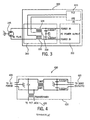
- the exemplary embodiment of a PC 300 includes a power supply 310 and a PLT AFE 320.
- a wire represented as wire 330 is wound on the same toroid core that supports the two common-mode one milliHenry (mH) inductors 335 of EMI filter 340.
- Coupling wire 330 with the existing core of inductors 335 provides an efficient coupling mechanism for the high-frequency data carrier to and from PLT AFE 320 and to and from an AC plug 345, without the need for a coupling capacitor or an additional transformer.
- filter 340 and hence wire 330 may be incorporated into PC 300, or in an alternative embodiment, EMI 340 includes wire 330 which may be external to PC 300 and configured as a power cord adapter module.
- the embodiment has a primary advantage of reducing costs as compared to conventional PLT coupling interfaces.
- the cost of an external port on the PC and a stand-alone cable along with a coupling module to the power line may be eliminated by using circuitry depicted in FIG 3 without sacrificing performance of a network.
- a further advantage of embodiment depicted in FIG 3 is the convenience of the end user of a network product because to use this technology, an end user needs to only connect the PC power cord to an AC outlet. No external connection to and from the PC to the power line is required other than the power cord itself.
- Another advantage of the embodiment depicted in FIG. 3 is that the coupling circuit to the power line may not have a pronounced loading effect on the power as compared with the impedance associated with a separate data communications line and a separate power supply line. Multiple loading effects on the power line are therefore eliminated.
- FIG. 4 depicts a PLT module 430 for enabling PLT functionality on devices being upgraded or retrofitted with a PLT card or PLT device.
- Module 400 includes the same circuitry as depicted in FIG.
- the circuitry to interface between power supply 405, load 410, and PLT jack 420 is integrated into a single module (or adapter) 430, which may be a module (or adapter) connected at the PC, at the AC plug, or anywhere in between.
- PLT module 430 adds significant benefits to the application of power line networking in existing PC systems.
- Third, but not so limited, the PLT module 430 is an intermediate module between the power line and the PC power supply, in addition to being a high-frequency signal coupler with an effective filter to minimize noise from the PC switching power supply that may effect adequate operation of the networking system.
- PLT module 430 which may be referred to as a PLT adapter, can be inserted externally between the AC socket of the PC power supply and the power cord that normally plugs into the AC socket.
- the PLT module 430 may have an input socket on one side much like the one found in the PC power supply, and an output plug on the other side, similar to the plug found in the PC power cord (that fits into the PC power supply socket).
- PLT module 430 would include a PLT interface jack 420 which may be a standard RJ11 type or BNC connector, or any other type of jack or connector, where the PLT add-on module would be connected for coupling to the power line.
- PLT module 430 could be completely molded in plastic, with input and output elements available for connection to the PC power supply, the power line, and the PLT add-on card or PLT device (internal or external).
- PLT module 430 may be completely embedded and molded within the PC power cord itself. Accordingly, the power cord itself would be a PLT adapter with an output for connection to the PLT add-on module, and the normal AC power connections to the power line at one end and the PC power supply at the other end.
- PLT module 430 although conceptually packaged in a different manner than the circuitry described with respect to FIG. 2 , includes a power line filter to de-couple noise from the PC power supply and the high-frequency signal coupling mechanism, as depicted in FIG. 2 .
- PLT networking interface 500 includes a PLT networking module 510 coupled between an AC power source 520, a load, such as a PC 530, and a PLT jack 540.
- PLT module 510 utilizes the same circuitry as depicted and described with respect to FIG. 3 .
- PLT module 510 is a power cord adapter with a coupling apparatus for power line networking.
- module 510 includes a PLT jack 540 for coupling to a PLT AFE to send and receive data signals to and from PLT AFE through AC power supply 520.
- PC power strip 600 includes a power cord 605 coupled to an electrical plug 610.
- Power cord 605 is coupled to a power filter with a PLT coupler 620.
- Power filter with PLT coupler 620 may be, in an exemplary embodiment, circuitry depicted in FIG. 4 or circuitry depicted in FIG. 5 , for example.
- Power strip 600 includes an integrated PLT jack 630 and a plurality of electrical outlets 640.
- Power strip 600 includes a built-in coupling apparatus 620 for PLT networking, including adequate filtering to de-couple noise from the computer system and its peripherals coupled to electrical outlets 640.
- Power strips 600 may be generalized, in an exemplary embodiment, to an improved wall-mount power adapter for PLT home networking, or to an improved wall electrical outlet containing an output jack for PLT signal coupling, having similar internal circuit topology as the power strip, such as the circuitry depicted in FIG 5 .
- PLT jack 630 may be, but is not limited to a standard RJ11 type jack.
- power strip 600 includes electrical outlets 650 which may be unfiltered outlets.
- Outlets 650 may be used to provide electrical power and data signals to devices that are already PLT compliant (i.e., the devices already contain filters, such as, but not limited to EMI filters 430 and 510, depicted in FIGs. 4 and 5 . In alternative exemplary embodiments electrical outlets 650 may not be present.
- power strip 600 adds significant benefits to the application of PLT networking.
- An empty outlet is not required in the vicinity of the PC system to couple a PC add-on card to the power line, which in some cases may avoid the purchase of an additional power strip.
- the user is not burdened with the task of deciding the best location to couple the add-on card to the power line, which would probably imply customer support calls to the card manufacturer and is not forced to reconfigure the existing inner connections of power cords to fit an additional clumsy plug module.
- Power strips 600 provides an intermediate filtering effect between the power line and the PC power supply with all peripherals, in addition to being a high-frequency signal coupler for the PLT data carrier signal, which minimizes noise from the various power supply interfaces and can substantially improve performance and operation of the PLT home networking system.
- exemplary embodiments refer to personal computers coupled to a home power line
- the invention may also be applied to other types of devices communicating on a network, not necessarily a home network, and not necessarily a personal computer.
- exemplary embodiments refer to specific types of jacks, couplers, and plugs, the terms are to be interpreted broadly. The embodiments may encompass those situations in which any type of electrical or optical, RF, ultrasonic, and the like coupling is made between the data processing device and the power supply.
Landscapes
- Engineering & Computer Science (AREA)
- Power Engineering (AREA)
- Computer Networks & Wireless Communication (AREA)
- Signal Processing (AREA)
- Cable Transmission Systems, Equalization Of Radio And Reduction Of Echo (AREA)
- Measurement And Recording Of Electrical Phenomena And Electrical Characteristics Of The Living Body (AREA)
- Dc Digital Transmission (AREA)
- Small-Scale Networks (AREA)
Claims (5)
- Vorrichtung zum Senden und Empfangen von elektrischen Datensignalen zu und von einer Stromleitung und zum Empfangen von elektrischer Energie von der Stromleitung, mit:einem Stromleitungskopplungsmittel (345), das ausgestaltet ist, um mit der Stromleitung gekoppelt zu sein;einer Stromversorgung (310);einem Datensignal-Transceiver (320);einem Interferenzfilter (340), das zwischen dem Stromleitungskopplungsmittel (345) und der Stromversorgung (310) gekoppelt und das ausgestaltet ist, um elektromagnetische Interferenz herauszufiltern; undeiner Kopplungsschaltung (330, 335), die zwischen dem Stromleitungskopplungsmittel (345) und dem Datensignal-Transceiver (320) gekoppelt ist, um elektrische Datensignale zwischen dem Datensignal-Transceiver (320) und dem Stromleitungskopplungsmittel (345) auszutauschen;dadurch gekennzeichnet, dass das Interferenzfilter (340) einen Ringkern, an dem zwei Gleichtakt-Induktoren (335) gehalten sind, und eine Kopplungsschaltung (330, 335) aufweist, die einen um den Ringkern des Interferenzfilters (340) gewickelten Draht (330) beinhaltet.
- Vorrichtung nach Anspruch 1, außerdem dadurch gekennzeichnet, dass das Interferenzfilter (340) und die Kopplungsschaltung (330, 335) in einen Personal-Computer (350) integriert sind.
- Vorrichtung nach Anspruch 1, außerdem dadurch gekennzeichnet, dass das Interferenzfilter (340) und die Kopplungsschaltung (330, 335) in einem Modul (510) integriert sind, das zwischen dem Stromleitungskopplungsmittel (345) und der Stromversorgung (310) gekoppelt ist.
- Vorrichtung nach Anspruch 1, außerdem dadurch gekennzeichnet, dass das Interferenzfilter (340) und die Kopplungsschaltung (330, 335) in einer Steckerleiste (600) integriert sind.
- Vorrichtung nach Anspruch 4, bei der die Steckerleiste (600) ein Stromkabel (605), das mit einem elektrischen Stecker (610) gekoppelt ist, und eine Mehrzahl von elektrischen Ausgängen (640) aufweist.
Applications Claiming Priority (3)
| Application Number | Priority Date | Filing Date | Title |
|---|---|---|---|
| US678983 | 2000-10-04 | ||
| US09/678,983 US6741162B1 (en) | 2000-10-04 | 2000-10-04 | Power line networking apparatus and method |
| PCT/US2001/030679 WO2002030003A2 (en) | 2000-10-04 | 2001-10-01 | Power line networking apparatus and method |
Publications (2)
| Publication Number | Publication Date |
|---|---|
| EP1323246A2 EP1323246A2 (de) | 2003-07-02 |
| EP1323246B1 true EP1323246B1 (de) | 2011-06-29 |
Family
ID=24725120
Family Applications (1)
| Application Number | Title | Priority Date | Filing Date |
|---|---|---|---|
| EP01981343A Expired - Lifetime EP1323246B1 (de) | 2000-10-04 | 2001-10-01 | Verfahren und vorrichtung für stromversorgungsnetz |
Country Status (6)
| Country | Link |
|---|---|
| US (1) | US6741162B1 (de) |
| EP (1) | EP1323246B1 (de) |
| CN (1) | CN1509526A (de) |
| AT (1) | ATE515112T1 (de) |
| AU (1) | AU2002212994A1 (de) |
| WO (1) | WO2002030003A2 (de) |
Families Citing this family (41)
| Publication number | Priority date | Publication date | Assignee | Title |
|---|---|---|---|---|
| US6480510B1 (en) | 1998-07-28 | 2002-11-12 | Serconet Ltd. | Local area network of serial intelligent cells |
| US6842459B1 (en) | 2000-04-19 | 2005-01-11 | Serconet Ltd. | Network combining wired and non-wired segments |
| US7615893B2 (en) * | 2000-05-11 | 2009-11-10 | Cameron International Corporation | Electric control and supply system |
| DE20018560U1 (de) * | 2000-10-30 | 2002-03-21 | CAMERON GmbH, 29227 Celle | Steuer- und Versorgungssystem |
| DE20115474U1 (de) * | 2001-09-19 | 2003-02-20 | Biester, Klaus, 29342 Wienhausen | Gleichspannungs-Wandlervorrichtung |
| DE20115471U1 (de) | 2001-09-19 | 2003-02-20 | Biester, Klaus, 29342 Wienhausen | Universelles Energieversorgungssystem |
| DE10142410A1 (de) * | 2001-08-31 | 2003-04-03 | Bosch Gmbh Robert | Versorgungsleitungsstruktur zur Energieversorgung von elektrischen Komponenten eines Kraftfahrzeugs |
| DE20115475U1 (de) * | 2001-09-19 | 2003-02-20 | Biester, Klaus, 29342 Wienhausen | Gleichspannungs-Wandlervorrichtung |
| US7020271B2 (en) * | 2003-06-12 | 2006-03-28 | Barbara Isabel Hummel | Ring control device |
| US7420459B2 (en) * | 2003-01-28 | 2008-09-02 | Gateway Inc. | Powerline networking device |
| US6972688B2 (en) * | 2003-01-28 | 2005-12-06 | Gateway Inc. | Power supply with modular integrated networking |
| IL154921A (en) | 2003-03-13 | 2011-02-28 | Mosaid Technologies Inc | A telephone system that includes many separate sources and accessories for it |
| FR2853482A1 (fr) * | 2003-04-07 | 2004-10-08 | France Telecom | Reseau local utilisant un reseau de distribution d'energie electrique et dispositif de reflexion associe |
| TW570406U (en) * | 2003-05-14 | 2004-01-01 | Abocom Sys Inc | Power device with a built-in power line network adaptor |
| TWI221691B (en) * | 2003-07-04 | 2004-10-01 | Primax Electronics Ltd | Hub protected from peak |
| AU2004310758B2 (en) * | 2003-12-01 | 2008-05-22 | Tyco Electronics Amp Gmbh | Electrical connector for data and energy supply |
| DE10360565A1 (de) * | 2003-12-22 | 2005-07-14 | BSH Bosch und Siemens Hausgeräte GmbH | Schaltungsanordnung zur Übertragung von Datensignalen von und/oder zu Hausgeräten |
| US7413471B2 (en) * | 2004-03-19 | 2008-08-19 | Asoka Usa Corporation | Integrated connector for powerline network and power supply |
| US7316586B2 (en) * | 2004-05-11 | 2008-01-08 | Adc Telecommunications, Inc. | Power sourcing unit for power over ethernet system |
| US7286026B2 (en) * | 2004-09-02 | 2007-10-23 | Avago Technologies Ecbu Ip (Singapore) Pte. Ltd. | Serial signal injection using capacitive and transformer couplings for power line communications |
| US7401239B2 (en) * | 2004-09-03 | 2008-07-15 | Asoka Usa Corporation | Internal powerline power supply method and system |
| US20060217847A1 (en) * | 2005-03-28 | 2006-09-28 | Adc Telecommunications, Inc. | Power sourcing unit for power over ethernet system |
| JP4708145B2 (ja) * | 2005-10-05 | 2011-06-22 | パナソニック株式会社 | 電力線通信装置 |
| JP5094004B2 (ja) * | 2005-10-20 | 2012-12-12 | パナソニック株式会社 | データ中継装置及びデータ中継方法 |
| CN101366160A (zh) * | 2005-12-29 | 2009-02-11 | 蒙斯特电缆产品公司 | 电力中心中的音频/视频媒体分布 |
| US7813099B2 (en) * | 2006-01-03 | 2010-10-12 | Asoka Usa Corporation | Power line outlet strip and method for powerline communications |
| US20080062003A1 (en) * | 2006-08-07 | 2008-03-13 | Christian Paetz | Wireless controllable power control device molded into a power cable |
| DE102006049402A1 (de) * | 2006-10-19 | 2008-04-30 | BSH Bosch und Siemens Hausgeräte GmbH | Powerline-Converter |
| GB2447483A (en) * | 2007-03-14 | 2008-09-17 | Siconnect Ltd | Transformer and common mode choke component |
| TWI437810B (zh) * | 2008-04-11 | 2014-05-11 | Acbel Polytech Inc | Exchange power supply with data communication function |
| US20100027599A1 (en) * | 2008-07-30 | 2010-02-04 | Anthony Di Chiro | Power Line Communications Adapter |
| FR2977415B1 (fr) * | 2011-06-30 | 2013-08-09 | Tda Armements Sas | Reseau d'interconnexion d'equipements pour vehicules par courants porteurs en ligne |
| US9325377B2 (en) | 2013-03-14 | 2016-04-26 | Qualcomm Incorporated | Powerline communication adapter for powerline communication systems |
| US9577707B1 (en) * | 2014-07-14 | 2017-02-21 | Marvell International Ltd. | Method and device for stabilizing impedance on a power-line communication device |
| CN104702096B (zh) * | 2015-02-05 | 2017-07-28 | 西安理工大学 | 含解耦电路的数字有源emi滤波系统及解耦电路的设计方法 |
| CN106341162A (zh) * | 2015-07-07 | 2017-01-18 | 华为技术有限公司 | 通信方法和设备 |
| CN111309660B (zh) * | 2020-02-17 | 2021-07-09 | 深圳市普威技术有限公司 | 主机设备、终端设备及数据交互系统 |
| WO2022099212A1 (en) * | 2020-11-09 | 2022-05-12 | Hydrocision, Inc. | System, apparatus, and method for electromagnetic interference mitigation |
| CN112422156B (zh) * | 2020-11-17 | 2022-07-26 | 广东电网有限责任公司 | 一种基于网络规模的低压电力线通信多局域网融合方法 |
| EP4432570A1 (de) * | 2023-03-15 | 2024-09-18 | Hangzhou Lianxintong Semiconductor Co., Ltd. | Schaltungsstruktur zur verbesserung der zuverlässigkeit von stromleitungskommunikation |
| EP4443752A1 (de) * | 2023-03-15 | 2024-10-09 | Hangzhou Lianxintong Semiconductor Co., Ltd. | Verdrahtetes kommunikationssystem zum ersetzen eines can/lin-busses in einem fahrzeug |
Family Cites Families (10)
| Publication number | Priority date | Publication date | Assignee | Title |
|---|---|---|---|---|
| DE3148351C2 (de) | 1980-12-08 | 1985-07-04 | Sharp K.K., Osaka | Entstörstecker |
| US4973940A (en) * | 1987-07-08 | 1990-11-27 | Colin Electronics Co., Ltd. | Optimum impedance system for coupling transceiver to power line carrier network |
| US5705974A (en) * | 1995-05-09 | 1998-01-06 | Elcom Technologies Corporation | Power line communications system and coupling circuit for power line communications system |
| US6115429A (en) * | 1995-08-04 | 2000-09-05 | Huang; Shih-Wei | Data receiving method for receiving data through predetermined clear zones of a powerline |
| US5805053A (en) | 1996-10-21 | 1998-09-08 | Elcom Technologies, Inc. | Appliance adapted for power line communications |
| US5777544A (en) * | 1997-03-17 | 1998-07-07 | Intellon Corporation | Apparatus and method for controlling data communications having combination of wide and narrow band frequency protocols |
| EP0981188A1 (de) | 1998-08-17 | 2000-02-23 | Ascom Systec AG | Anordnung zur Uebermittlung von Nachrichten über ein Niederspannungs-Stromversorgungsnetz sowie Zwischenstück |
| TW459425B (en) * | 2000-06-23 | 2001-10-11 | Primax Electronics Ltd | Power socket apparatus |
| US6747859B2 (en) | 2000-07-11 | 2004-06-08 | Easyplug Inc. | Modular power line network adapter |
| US6549120B1 (en) * | 2000-11-24 | 2003-04-15 | Kinectrics Inc. | Device for sending and receiving data through power distribution transformers |
-
2000
- 2000-10-04 US US09/678,983 patent/US6741162B1/en not_active Expired - Lifetime
-
2001
- 2001-10-01 WO PCT/US2001/030679 patent/WO2002030003A2/en not_active Ceased
- 2001-10-01 CN CNA01819964XA patent/CN1509526A/zh active Pending
- 2001-10-01 EP EP01981343A patent/EP1323246B1/de not_active Expired - Lifetime
- 2001-10-01 AT AT01981343T patent/ATE515112T1/de not_active IP Right Cessation
- 2001-10-01 AU AU2002212994A patent/AU2002212994A1/en not_active Abandoned
Also Published As
| Publication number | Publication date |
|---|---|
| US6741162B1 (en) | 2004-05-25 |
| WO2002030003A2 (en) | 2002-04-11 |
| CN1509526A (zh) | 2004-06-30 |
| EP1323246A2 (de) | 2003-07-02 |
| WO2002030003A3 (en) | 2002-08-15 |
| AU2002212994A1 (en) | 2002-04-15 |
| ATE515112T1 (de) | 2011-07-15 |
Similar Documents
| Publication | Publication Date | Title |
|---|---|---|
| EP1323246B1 (de) | Verfahren und vorrichtung für stromversorgungsnetz | |
| US6972688B2 (en) | Power supply with modular integrated networking | |
| US6483203B1 (en) | Single unit integrated transformer assembly | |
| EP1935112B1 (de) | Stromversorgungsvorrichtung und stromleitungs-kommunikationsvorrichtung dafür | |
| CN104733966B (zh) | 用于有源电缆的电路 | |
| US7660345B2 (en) | Transceiver apparatus and method having ethernet-over-power and power-over-ethernet capability | |
| US20050194909A1 (en) | AC adapter integral-type household-power-line coupler | |
| WO1998018211A1 (en) | Appliance adapted for power line communications | |
| US6650549B1 (en) | Hub having a bluetooth system | |
| US6912145B2 (en) | Power injector apparatus | |
| JP2003517230A (ja) | 低電圧電源網を介して情報を伝送する装置 | |
| US20100261386A1 (en) | Power line carrier network combined with power supply | |
| US20040130413A1 (en) | Power supply system and method using analog coupling circuitry for power-line communications | |
| CN108880828B (zh) | 一种供电设备pse及共模差模自适应供电的方法 | |
| TWI321406B (de) | ||
| CA2171455A1 (en) | Line interface apparatus and method for isolating data terminal equipment from the line | |
| US6992599B2 (en) | Terminal adapter for connecting a terminal to a computer local area network capable of identifying any of several terminal types | |
| US6307764B1 (en) | Power brick | |
| US5995591A (en) | Connecting arrangement for reducing induced noise | |
| KR101205300B1 (ko) | 직류 기반의 2선식 비디오 도어폰 시스템 | |
| KR200311912Y1 (ko) | 전력선 통신용 가전기기의 전원 인출 구조 | |
| US7408753B2 (en) | Surge-protected networking power strip | |
| TWM482195U (zh) | 外接式訊號電源耦合裝置 | |
| CN223461868U (zh) | 一种具有UART通信功能的Type-C接口 | |
| US6463113B1 (en) | External signal attenuator for a single-ended transmission line |
Legal Events
| Date | Code | Title | Description |
|---|---|---|---|
| PUAI | Public reference made under article 153(3) epc to a published international application that has entered the european phase |
Free format text: ORIGINAL CODE: 0009012 |
|
| 17P | Request for examination filed |
Effective date: 20030411 |
|
| AK | Designated contracting states |
Designated state(s): AT BE CH CY DE DK ES FI FR GB GR IE IT LI LU MC NL PT SE TR |
|
| AX | Request for extension of the european patent |
Extension state: AL LT LV MK RO SI |
|
| R17C | First examination report despatched (corrected) |
Effective date: 20060918 |
|
| GRAP | Despatch of communication of intention to grant a patent |
Free format text: ORIGINAL CODE: EPIDOSNIGR1 |
|
| GRAS | Grant fee paid |
Free format text: ORIGINAL CODE: EPIDOSNIGR3 |
|
| RAP1 | Party data changed (applicant data changed or rights of an application transferred) |
Owner name: CONEXANT SYSTEMS, INC. |
|
| GRAA | (expected) grant |
Free format text: ORIGINAL CODE: 0009210 |
|
| AK | Designated contracting states |
Kind code of ref document: B1 Designated state(s): AT BE CH CY DE DK ES FI FR GB GR IE IT LI LU MC NL PT SE TR |
|
| REG | Reference to a national code |
Ref country code: GB Ref legal event code: FG4D |
|
| REG | Reference to a national code |
Ref country code: CH Ref legal event code: EP |
|
| REG | Reference to a national code |
Ref country code: IE Ref legal event code: FG4D |
|
| REG | Reference to a national code |
Ref country code: DE Ref legal event code: R096 Ref document number: 60144886 Country of ref document: DE Effective date: 20110818 |
|
| REG | Reference to a national code |
Ref country code: NL Ref legal event code: VDEP Effective date: 20110629 |
|
| PG25 | Lapsed in a contracting state [announced via postgrant information from national office to epo] |
Ref country code: SE Free format text: LAPSE BECAUSE OF FAILURE TO SUBMIT A TRANSLATION OF THE DESCRIPTION OR TO PAY THE FEE WITHIN THE PRESCRIBED TIME-LIMIT Effective date: 20110629 |
|
| PG25 | Lapsed in a contracting state [announced via postgrant information from national office to epo] |
Ref country code: FI Free format text: LAPSE BECAUSE OF FAILURE TO SUBMIT A TRANSLATION OF THE DESCRIPTION OR TO PAY THE FEE WITHIN THE PRESCRIBED TIME-LIMIT Effective date: 20110629 Ref country code: AT Free format text: LAPSE BECAUSE OF FAILURE TO SUBMIT A TRANSLATION OF THE DESCRIPTION OR TO PAY THE FEE WITHIN THE PRESCRIBED TIME-LIMIT Effective date: 20110629 Ref country code: GR Free format text: LAPSE BECAUSE OF FAILURE TO SUBMIT A TRANSLATION OF THE DESCRIPTION OR TO PAY THE FEE WITHIN THE PRESCRIBED TIME-LIMIT Effective date: 20110930 |
|
| PG25 | Lapsed in a contracting state [announced via postgrant information from national office to epo] |
Ref country code: BE Free format text: LAPSE BECAUSE OF FAILURE TO SUBMIT A TRANSLATION OF THE DESCRIPTION OR TO PAY THE FEE WITHIN THE PRESCRIBED TIME-LIMIT Effective date: 20110629 |
|
| PG25 | Lapsed in a contracting state [announced via postgrant information from national office to epo] |
Ref country code: PT Free format text: LAPSE BECAUSE OF FAILURE TO SUBMIT A TRANSLATION OF THE DESCRIPTION OR TO PAY THE FEE WITHIN THE PRESCRIBED TIME-LIMIT Effective date: 20111031 Ref country code: NL Free format text: LAPSE BECAUSE OF FAILURE TO SUBMIT A TRANSLATION OF THE DESCRIPTION OR TO PAY THE FEE WITHIN THE PRESCRIBED TIME-LIMIT Effective date: 20110629 |
|
| PG25 | Lapsed in a contracting state [announced via postgrant information from national office to epo] |
Ref country code: CY Free format text: LAPSE BECAUSE OF FAILURE TO SUBMIT A TRANSLATION OF THE DESCRIPTION OR TO PAY THE FEE WITHIN THE PRESCRIBED TIME-LIMIT Effective date: 20110629 |
|
| PLBE | No opposition filed within time limit |
Free format text: ORIGINAL CODE: 0009261 |
|
| STAA | Information on the status of an ep patent application or granted ep patent |
Free format text: STATUS: NO OPPOSITION FILED WITHIN TIME LIMIT |
|
| PG25 | Lapsed in a contracting state [announced via postgrant information from national office to epo] |
Ref country code: MC Free format text: LAPSE BECAUSE OF NON-PAYMENT OF DUE FEES Effective date: 20111031 Ref country code: IT Free format text: LAPSE BECAUSE OF FAILURE TO SUBMIT A TRANSLATION OF THE DESCRIPTION OR TO PAY THE FEE WITHIN THE PRESCRIBED TIME-LIMIT Effective date: 20110629 |
|
| REG | Reference to a national code |
Ref country code: CH Ref legal event code: PL |
|
| 26N | No opposition filed |
Effective date: 20120330 |
|
| PG25 | Lapsed in a contracting state [announced via postgrant information from national office to epo] |
Ref country code: DK Free format text: LAPSE BECAUSE OF FAILURE TO SUBMIT A TRANSLATION OF THE DESCRIPTION OR TO PAY THE FEE WITHIN THE PRESCRIBED TIME-LIMIT Effective date: 20110629 |
|
| PG25 | Lapsed in a contracting state [announced via postgrant information from national office to epo] |
Ref country code: CH Free format text: LAPSE BECAUSE OF NON-PAYMENT OF DUE FEES Effective date: 20111031 Ref country code: LI Free format text: LAPSE BECAUSE OF NON-PAYMENT OF DUE FEES Effective date: 20111031 |
|
| REG | Reference to a national code |
Ref country code: IE Ref legal event code: MM4A |
|
| REG | Reference to a national code |
Ref country code: DE Ref legal event code: R097 Ref document number: 60144886 Country of ref document: DE Effective date: 20120330 |
|
| PG25 | Lapsed in a contracting state [announced via postgrant information from national office to epo] |
Ref country code: IE Free format text: LAPSE BECAUSE OF NON-PAYMENT OF DUE FEES Effective date: 20111001 |
|
| PG25 | Lapsed in a contracting state [announced via postgrant information from national office to epo] |
Ref country code: ES Free format text: LAPSE BECAUSE OF FAILURE TO SUBMIT A TRANSLATION OF THE DESCRIPTION OR TO PAY THE FEE WITHIN THE PRESCRIBED TIME-LIMIT Effective date: 20111010 |
|
| PG25 | Lapsed in a contracting state [announced via postgrant information from national office to epo] |
Ref country code: LU Free format text: LAPSE BECAUSE OF NON-PAYMENT OF DUE FEES Effective date: 20111001 |
|
| PG25 | Lapsed in a contracting state [announced via postgrant information from national office to epo] |
Ref country code: TR Free format text: LAPSE BECAUSE OF FAILURE TO SUBMIT A TRANSLATION OF THE DESCRIPTION OR TO PAY THE FEE WITHIN THE PRESCRIBED TIME-LIMIT Effective date: 20110629 |
|
| PGFP | Annual fee paid to national office [announced via postgrant information from national office to epo] |
Ref country code: GB Payment date: 20141027 Year of fee payment: 14 Ref country code: FR Payment date: 20141017 Year of fee payment: 14 Ref country code: DE Payment date: 20141029 Year of fee payment: 14 |
|
| REG | Reference to a national code |
Ref country code: DE Ref legal event code: R119 Ref document number: 60144886 Country of ref document: DE |
|
| GBPC | Gb: european patent ceased through non-payment of renewal fee |
Effective date: 20151001 |
|
| PG25 | Lapsed in a contracting state [announced via postgrant information from national office to epo] |
Ref country code: DE Free format text: LAPSE BECAUSE OF NON-PAYMENT OF DUE FEES Effective date: 20160503 Ref country code: GB Free format text: LAPSE BECAUSE OF NON-PAYMENT OF DUE FEES Effective date: 20151001 |
|
| REG | Reference to a national code |
Ref country code: FR Ref legal event code: ST Effective date: 20160630 |
|
| PG25 | Lapsed in a contracting state [announced via postgrant information from national office to epo] |
Ref country code: FR Free format text: LAPSE BECAUSE OF NON-PAYMENT OF DUE FEES Effective date: 20151102 |