EP1323481A2 - Schwingungskupplung an einem Ultraschallhandstück - Google Patents
Schwingungskupplung an einem Ultraschallhandstück Download PDFInfo
- Publication number
- EP1323481A2 EP1323481A2 EP02007944A EP02007944A EP1323481A2 EP 1323481 A2 EP1323481 A2 EP 1323481A2 EP 02007944 A EP02007944 A EP 02007944A EP 02007944 A EP02007944 A EP 02007944A EP 1323481 A2 EP1323481 A2 EP 1323481A2
- Authority
- EP
- European Patent Office
- Prior art keywords
- vibration
- horn
- ultrasonic
- working plane
- hand piece
- Prior art date
- Legal status (The legal status is an assumption and is not a legal conclusion. Google has not performed a legal analysis and makes no representation as to the accuracy of the status listed.)
- Granted
Links
Images







Classifications
-
- B—PERFORMING OPERATIONS; TRANSPORTING
- B06—GENERATING OR TRANSMITTING MECHANICAL VIBRATIONS IN GENERAL
- B06B—METHODS OR APPARATUS FOR GENERATING OR TRANSMITTING MECHANICAL VIBRATIONS OF INFRASONIC, SONIC, OR ULTRASONIC FREQUENCY, e.g. FOR PERFORMING MECHANICAL WORK IN GENERAL
- B06B3/00—Methods or apparatus specially adapted for transmitting mechanical vibrations of infrasonic, sonic, or ultrasonic frequency
-
- A—HUMAN NECESSITIES
- A61—MEDICAL OR VETERINARY SCIENCE; HYGIENE
- A61B—DIAGNOSIS; SURGERY; IDENTIFICATION
- A61B17/00—Surgical instruments, devices or methods
- A61B17/32—Surgical cutting instruments
- A61B17/320068—Surgical cutting instruments using mechanical vibrations, e.g. ultrasonic
- A61B2017/320098—Surgical cutting instruments using mechanical vibrations, e.g. ultrasonic with transverse or torsional motion
Definitions
- the invention of the present Application concerns a complex vibration ultrasonic hand piece, and more particularly, a complex vibration ultrasonic hand piece for reducing the reciprocating rotation speed of non working plane less than the speed of the working plane by generating a composite vibration composed of a longitudinal vibration in the horn central axial direction and a torsional vibration having the horn central axis as a fulcrum at a horn tip by converting the longitudinal vibration from a vibration source and, on the other hand, by forming a speed variation mechanism of torsional vibration in the composite vibration at the female portion of the horn tip.
- the complex vibration ultrasonic hand piece has been used as one of various instruments of operation in the surgery domain, or as apparatus for processing of a variety of materials.
- Fig. 10 shown a conventional complex vibration ultrasonic hand piece as operation instrument, configured to generate a high frequency by an ultrasonic wave oscillation circuit, and convert this high frequency electric power into a mechanical ultrasonic vibration of a female portion 4a by a hand piece 1 as shown in Fig. 10.
- the illustrated hand piece 1 comprises a built-in vibration mechanism 3 (electrostrictive element type, magnetostrictive type) as shown in Fig. 10 (b) in a tubular member 2 composing the outer shell thereof, and the same is configured to be fixed to a horn 4 projecting from the tubular member 2.
- a built-in vibration mechanism 3 electrostrictive element type, magnetostrictive type
- the vibration mechanism 3 is composed of a vibrator 3a, a metallic backing plates 3b attached to both ends thereof and a front plate 3c, a high frequency electric power supplied from an ultrasonic oscillation circuit out of the drawing is converted into a mechanical vibration by the vibration mechanism 3, and this mechanical vibration is transmitted to a tip 4b of a horn 4 of a female portion.
- 5 is an irrigation pipe for supplying an operation area with physiological saline or the like
- 6 is a suction pipe for collecting blood, excised fragments generated along with the operation, or others from a suction port 4b.
- a suction duct 3d communicating with the suction port 4b is sometimes formed at the middle portion of the vibration mechanism 3 as shown in Fig. 10 (c), to combine the cooling function of the vibration mechanism 3 at the same time.
- the vibration of the horn tip becoming a working portion in the operation in a living body and the processing of various materials, or others is restricted by the vibration element constituting the ultrasonic oscillation mechanism.
- the vibration element constituting the ultrasonic oscillation mechanism.
- longitudinal vibration where the properties of the vibration element are parallel to the axial direction, it results in the generation of longitudinal vibration at the horn tip.
- a so-called torsional vibration repeatedly rotating around the axe is required to the operation area in order to plan the efficiency of necessary works such as cutting or the like, or to perform sharply and smoothly a fine operation.
- a configuration for obtaining a vertical-torsional composite vibration by composing the vibration element of the vibration mechanism with a longitudinal vibration element and a torsional vibration element may be devised; however, the structure of the ultrasonic oscillation mechanism becomes complicated and heavy, not only making the handling difficult but also increasing the load of the output system of high frequency electric power and creating problems not only in respect of manufacturing cost but also running cost, and therefore is not composed practical actually.
- a drill has been used for cutting hard tissues of a living body, and it is feared that nerves and vessels be caught by the drill rotation in an area where nerves, vessels or others are entangled complicatedly. Therefore, it can not be used in the vicinity of nerve or vessel, and cases where the operation was composed impossible were not rear.
- a complex vibration ultrasonic hand piece comprising an ultrasonic oscillation mechanism composed of a longitudinal vibration element, backing plates attached to both ends thereof and a front plate for generating an ultrasonic vibration of a predetermined frequency, a horn coupled with this ultrasonic oscillation mechanism for amplifying the vibration transmitted from said ultrasonic oscillation mechanism, a vibration conversion mechanism for converting the vibration transmitted from said ultrasonic oscillation mechanism into a composite vibration composed of a longitudinal vibration in the horn central axial direction and a torsional vibration having the horn central axis as fulcrum, and a female portion provided with a working plane and disposed at said horn tip, wherein:
- said horn is composed of a horn of 1 / 2 wavelength or more, and a converter mechanism of torsional vibration in said composite vibration is formed in said female portion, for reducing the reciprocating rotation speed of non working plane less than the speed of the working plane.
- the groove portions are sometimes juxtaposed in plurality
- said speed variation mechanism of reciprocating rotation in the female portion is composed of a projection portion formed on a shaft portion side face of the female portion, and a working plane is provided at a projection portion tip plane for reducing the torsional vibration speed of the non working plane less than the speed of the working plane.
- the speed variation mechanism of reciprocating rotation in the female portion is composed of a curved surface body having a small diameter portion and a large diameter portion formed on a tip of the female portion, and a working plane is provided on the large diameter portion for reducing the torsional vibration speed of the non working plane less than the speed of the working plane.
- said curved surface body is sometimes composed of a sphere or a pseudo sphere.
- the curved surface body is sometimes composed of a spindle or a pseudo spindle.
- the groove portion is sometimes formed spiral.
- said groove portion is has a predetermined deflection angle ⁇ , and this deflection angle is sometimes set to 0 ⁇ ⁇ ⁇ 9 0 degrees.
- the groove portion is sometimes disposed in the vicinity of the loop position of the torsional vibration.
- a torsional vibration attenuation means is sometimes provided between the groove portion and an electrostrictive element of the ultrasonic oscillation mechanism, and this torsional vibration attenuation means is composed of a circumferential surface portion of a diameter larger than the circumferential surface portion where the groove portion is formed.
- this torsional vibration attenuation means is composed of a buffer having a cross-section larger than the cross-section (longitudinal portion in respect to the axial direction) in the groove portion, and the portion shape of the buffer may be formed square, circular, or various others forms.
- the vibration conversion mechanism comprises sometimes a body detachably interposed between the horn and the ultrasonic oscillation mechanism and a groove portion formed around the body circumferential surface.
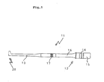
- Fig. 1 is a side view of the ultrasonic hand piece according to a first embodiment of the invention of the present Application.
- 11 is an ultrasonic hand piece, comprising an ultrasonic oscillation mechanism 12 and an ultrasonic horn 13 joined to the same, and they are inserted into a outer cylinder not shown.
- the ultrasonic oscillation mechanism 12 comprises a longitudinal vibration element 14, and a front plate 15 and a backing plate 16 placed at both ends thereof.
- a vibration conversion mechanism 17 for converting the vibration transmitted from said ultrasonic oscillation mechanism 12 into a (vertical-torsional) composite vibration composed of a longitudinal vibration in the central axial direction of the ultrasonic horn 13 and a torsional vibration having the central axis of the ultrasonic horn 13 as fulcrum is provided in the vicinity of the end portion of the ultrasonic horn 13.
- 20 is a female portion provided at the tip of said ultrasonic horn 13.
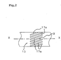
- the vibration conversion mechanism 17 is, in the embodiment, composed of a plurality of groove portions 17a formed to be wound around the circumferential surface of the ultrasonic horn 13 as shown in Fig. 2.
- These plurality of groove portions 17a are carved in parallel with a predetermined interval respectively and have a predetermined deflection angle ⁇ with the central axis X-X of the ultrasonic horn 13 on the circumferential surface, and this deflection angle ⁇ is set in a range of 0 degree ⁇ ⁇ ⁇ 9 0 degrees.
- the shape of the groove portion 17a is rectangular, and the width thereof is set to a range of 0.5 to 5 mm, the length 3 to 30 mm and the depth 0.5 mm or more. It should be appreciated that the set position of the groove portion as vibration conversion mechanism 17 is not limited to the horn circumferential surface, but it can be formed on the outside face of any one of the horn, sound wave oscillation mechanism between the horn tip and the electrostrictive element thereof or members interposed between the horn and the sound wave oscillation mechanism.
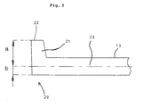
- Fig. 3 is an enlarged view of said female portion 20 and, in the drawing, 21 is a projection portion as speed variation mechanism and, is formed on the shaft side face of the female portion 20.
- a working plane 22 is formed on a tip face of the projection portion 21 is formed for cutting hard tissues or others by composite vibration. It should be appreciated that a indicates the distance between the working plane 22 and the central axis 23 of the torsional vibration, b the distance between the shaft side face of the female portion 20 and said central axis 23, and it is set to a > b.
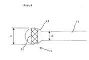
- Fig. 4 is an enlarged view of the female portion 20 according to another embodiment.
- 24 is a curved surface body as speed variation mechanism of torsional vibration, and here, a sphere is used as curved surface body, and a working plane 25 is formed all around the large diameter portion (vicinity thereof including the diameter portion) of this sphere 24.
- the working plane 25 has a surface formed into a rough particulate or file shape in order to facilitate cutting operation or others of a hard tissue.
- the portion other than the working plane 25 of the sphere 24 surface, namely non working plane, is formed smooth in order to prevent damage to the nerve, vessel, or the like during the intervention operation or others. It should be appreciated that c indicates the diameter of the sphere 24, d the diameter of the shaft of the female portion, and they are set to c > d.
- a spindle 34 as shown in Fig. 5 or one having a shape similar to the same can also be used as this curved surface body.
- a working plane 35 is formed all around at the middle portion of the spindle 34.
- the working plane 35 has a surface formed into a rough particulate or file shape in order to facilitate cutting operation or others of a hard tissue.
- the portion other than the working plane 35 of the spindle 34 surface, namely non working plane, is formed smooth in order to prevent damage to the nerve, vessel, or the like during the intervention operation or others.
- a body similar to the spindle as shown in Fig. 6 can also be used as this curved surface body.
- 44 is a body having an elliptical portion to be used as curved surface body, and a working plane 45 is formed all around at the middle portion thereof.
- the portion other than the working plane 45 of this curved surface body 44 surface, namely non working plane, is formed smooth in order to prevent damage to the nerve, vessel, or the like during the intervention operation or others.
- this groove portion may be composed of a single groove 17b formed to surround the surface of the ultrasonic horn 13 as shown in Fig. 7.
- this groove 17b also has a predetermined deflection angle ⁇ with the central axis of the ultrasonic horn 13 on the circumferential surface, and this deflection angle ⁇ is set in a range of 0 degree ⁇ ⁇ ⁇ 9 0 degrees.
- the width and depth of this groove 17b are also set to ranges of 0.5 to 5 mm, 0.5 mm or more respectively, similarly to said embodiment.
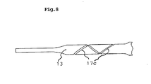
- Fig. 8 is a side view of the ultrasonic horn according to a second embodiment.
- the vibration conversion mechanism 17 is composed of a spiral groove portion 17c formed to surround the surface of the ultrasonic horn 13. And, this groove 17c also has a predetermined deflection angle ⁇ with the central axis of the ultrasonic horn 13 on the circumferential surface similarly to the forgoing, and this deflection angle ⁇ is set in a range of 0 degree ⁇ ⁇ ⁇ 9 0 degrees.
- the groove width and depth are also set to ranges of 0.5 to 5 mm, 0.5 mm or more respectively, similarly to said embodiment.
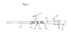
- Fig. 9 is a side view of the ultrasonic horn according to a third embodiment.
- the vibration conversion mechanism 17 is composed of a body 18 interposed detachably between the ultrasonic horn 13 and the ultrasonic oscillation mechanism 12 and one or more groove portions 17a formed on this body 18 circumferential surface as illustrated.
- the body 18 is coupled respectively detachably by a backing plate 16 and bolts 19, 19 in the ultrasonic horn 13 and the ultrasonic oscillation mechanism 12 as illustrated.
- the embodiment, allowing to remove simply the vibration conversion mechanism 17, has an advantage that it is enough to remove the vibration conversion mechanism 17 and connecting directly the ultrasonic horn 13 and the ultrasonic oscillation mechanism 12, for instance, in case of desiring to use only with longitudinal vibration.
- the groove portion to be formed in the body 18 are composed of a plurality of parallel groove portions 17a formed to surround the circumferential surface of the body 18; however, as shown in Fig. 7, Fig. 8 concerning respective embodiments mentioned above, it may composed of a single groove 17b formed to surround the surface of the body 18 or a spiral groove portion 17c formed to surround the surface of the body 18.
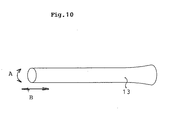
- Fig. 10 is a drawing showing the movement at the tip of the ultrasonic horn 13, the tips of the ultrasonic horn 13 results in performing a rapid reciprocating rotation (torsional vibration) in the arrow A direction around the central axis and, on the other hand, a rapid reciprocating movement (longitudinal vibration) in the arrow B direction along the central axis, through composition of longitudinal vibration and torsional vibration generated by converting the longitudinal vibration in the vibration conversion mechanism 17.
- FIG. 11 is a schematic diagram showing the live bone cutting operation by an ultrasonic hand piece (ultrasonic scalpel) according to the invention of the present Application and, as a torsional vibration is output to a scalpel (horn) 13 tip in addition to a longitudinal vibration, a rapid reciprocating rotation (torsional vibration) is generated in the arrow A direction at the scalpel (horn) 13.
- a side end portion 13 a of the scalpel (horn) 13 tip cuts the live bone, and a gap K is formed between the scalpel (horn) 13 tip and the live bone, allowing to perform the cutting extremely smoothly even for the cutting in the depths of a live bone.
- the cutting function by the longitudinal vibration of the scalpel tip, accompanying a torsional moment not only improves considerably the tissue shearing efficiency, but also realizes a cutting in a clean state, because the definition or so-called sharpness in the cutting function is improved remarkably, and the tissues in the cutting area do not collapse or else.
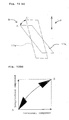
- a corner portion A of the groove portion 17a repeats the reciprocation movement between the home position and the A' point. And this results in generation of the same in all areas of the groove portion.
- Fig. 12(b) is a drawing where the locus of said corner portion A is represented in a graph taking the Y-axis as vertical direction movement and the X-axis as transversal direction movement of the locus of said corner portion A. According to this, the corner portion A moves reciprocally between the origin and the A' point all the way moving in the transversal direction in addition to the vertical direction, and it is understood that a reciprocating movement in the transversal direction generates as torsional vibration component.
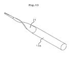
- the vibration conversion can also be obtained by a helical body shown in Fig. 13.
- 21 is an integrally formed helix portion in an ultrasonic horn 13a.
- Fig. 14 illustrates the operation of the female portion 20 shown in Fig. 3.
- a projection portion 21 as speed variation mechanism of torsional vibration make a torsional vibration around the central axis 23 of the torsional vibration as illustrated, but the displacement speed of a non-working plane 22a becomes lower than a working plane 22.
- a fixed point 22b on the working plane 22 rotates reciprocally between points 22c and 22d.
- a fixed point 22e of the non-working plane 22a corresponding said fixed point 22b rotates reciprocally with points 22f and 22g.
- Fig. 14 illustrates the operation of the female portion 20 shown in Fig. 3.
- a projection portion 21 as speed variation mechanism of torsional vibration, make a torsional vibration around the central axis 23 of the torsional vibration as illustrated, but the displacement speed of a non-working plane 22a becomes lower than a working plane 22.
- a fixed point 22b on the working plane 22 rotates reciprocally between points 22c and 22d.
- the distance between the fixed point 22b of the working plane 22 and the central axis 23 is a
- the displacement speed of the fixed point 22b of the working plane 22 becomes a / b times of the displacement speed of the fixed point 22e of the non-working plane 22a.
- the torsional vibration speed of the non-working plane 22 is reduced by the projection portion 21 as speed variation mechanism. Therefore, the crushing force of the non-working plane 22 becomes weaker than the working plane 22, and the possibility of damaging areas other than a predetermined area with the non-working plane 22 is reduced, during cutting, crushing or other operations of the predetermined area by the working plane 22.
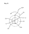
- Fig. 15 illustrates the operation of the female portion 20 shown in Fig. 4.
- 24 is a sphere as speed variation mechanism of torsional vibration and a working plane 25 is formed all around the large diameter portion (vicinity thereof including the diameter portion) of this sphere 24.
- the vibration speed of the fixed point 26a is smaller than the fixed point 25a.
- the surface there of formed into rough granular or file shape to facilitate cutting operation or others of hard tissues is formed smooth in a way to prevent damage of nerves, blood vessels or others in a surgical operation and so on.
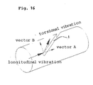
- the torsional vibration is obtained by bending a part of the longitudinal vibration component and generating a vibration in a direction different from the vertical direction.
- this component becomes the composition of the vertical wave and the transversal wave; however, as it is difficult to represent this composition theoretically (mathematically), respective components of the vertical wave and the transversal wave are represented in a vector-like manner.
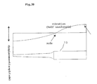
- the groove portion for generating a torsional vibration from a longitudinal vibration is disposed in the vicinity of the loop position (including the vicinity thereof) of the torsional vibration as shown in Fig. 17.
- 2 is an ultrasonic horn composed of titanium alloy
- 3 is a backing plate interposed between a (not shown) ultrasonic vibrator and an ultrasonic horn 1
- the groove portion is juxtaposed in plurality in a vicinity range 4 of the loop position of the torsional vibration, on the circumferential surface of the ultrasonic horn 1, and respective groove portion has a predetermined deflection angle ⁇ (0 ⁇ ⁇ ⁇ 9 0 degrees) in respect to the central axis of the horn.
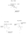
- Fig. 17 shows the correlation of the position of the groove portion, longitudinal vibration, and torsional vibration based on experimental results and, in Fig. 17(a), the groove portion 1 is placed slightly near the vibrator from the loop position of the vibration, and as shown, the torsional vibration frequency is lower than the case of loop position. Also, in Fig. 17(b), the groove portion 1 is placed at the loop position of the vibration, and in this case, respective vibration frequencies of the longitudinal vibration and the torsion agree, vertical-torsional vibrations coexist respectively, resulting in the acquisition of an optimal composite vibration.
- the torsional vibration is a composite vibration of vertical wave (wave displacing in the vibration progression direction) and transversal wave (wave displacing perpendicularly to the vibration progression direction) and in case of vibrating with a same frequency, the length of half wavelength will be different due to the difference between the vertical wave speed and the transversal wave speed, and the length of half wavelength of the torsional vibration becomes shorter than the longitudinal vibration.
- the set position of the groove portion will automatically be the predetermined position, namely the torsional vibration loop position.
- the groove portion 1 is disposed in the vicinity of the torsional vibration loop position, the proportion of longitudinal vibration and torsional vibration can be converted variously, by changing the nature and shape of the groove.
- Fig. 18 is a schematic diagram showing the variation of proportion of longitudinal vibration and torsional vibration in case of various changes of the deflection angle ⁇ in respect to the horn central axis of the groove portion 1.
- the depth of the groove portion influences the generation mechanism of torsional vibration.
- the deeper is the groove portion the more is the longitudinal vibration component crossing with the groove portion, and consequently, the conversion quantity into torsional vibration increases; in other words, the deeper is the groove portion, the more becomes the torsional vibration component.
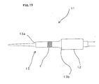
- Fig. 19 is a side view of the ultrasonic hand piece according to said embodiment.
- 11 is an ultrasonic hand piece, comprising an ultrasonic oscillation mechanism 12 and an ultrasonic horn 13 joined to the same, and they are inserted into a now shown outer cylinder.
- the ultrasonic oscillation mechanism 12 is the one of a well-known configuration having a longitudinal vibration element and a front plate and a backing plate placed at both ends thereof. It should be appreciated that 13a, 13b are respectively a restriction portion and a torsional vibration attenuation means mentioned below.
- a plurality of groove portion 1 for converting the vibration transmitted from said ultrasonic oscillation mechanism 12 into a vertical-torsional composite vibration are disposed in the vicinity of the end portion of the ultrasonic horn 13.
- the shape of the groove portion 1 is rectangular, and the width thereof is set to a range of 0.5 to 5 mm, the length 3 to 30 mm and the depth 0.5 mm or more.
- the horn length corresponding to a predetermined longitudinal vibration can be determined.
- a restriction portion 13a is formed on the ultrasonic horn 13, and this restriction portion 13a converges the longitudinal vibration transmitted in the axial direction and allows increasing the apparent speed.
- the loop position is set in the ultrasonic horn 13 so that the torsional vibration be a length appropriate for the longitudinal vibration frequency (25 KHz) and the other required performance, and under this condition, the total length of the ultrasonic horn 13 is designed so that the longitudinal vibration be furthermore appropriate for the predetermined 25KHz, and at the same time, the ultrasonic horn 13 according to the other necessity, and at this time, the position of the joint F or the longitudinal vibration component has the same effect if it is set to the left of a loop position H of the torsional vibration component as illustrated, or to the right of the loop position H.
- a torsional vibration attenuation means is set between the groove portion and the ultrasonic oscillation mechanism for preventing heat generation from the vibrator, deterioration of the electrostrictive element or others, by attenuating the torsional vibration to be transmitted to the vibrator side, and in this embodiment, a circumferential surface portion having a diameter larger than the circumferential portion where the groove portion is formed on the ultrasonic horn 13 is disposed in the ultrasonic oscillation mechanism of the ultrasonic horn, to compose thereby a torsional vibration attenuation means.
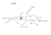
- 13b is a torsional vibration attenuation means formed at the vibrator side of the rear end of the ultrasonic horn 13, composed of a large diameter portion 14 at the rear end portion of the ultrasonic horn 13, and an ultrasonic oscillation mechanism 12 having the same diameter as the same.
- the diameter of said large diameter portion 14 and the ultrasonic oscillation mechanism 12 joined with the same is b which is larger than a, and the torsional vibration generated by the groove portion 1 leads to said large diameter portion 14 and ultrasonic oscillation mechanism 12, and results in being diffused and attenuated.
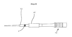
- the torsional vibration attenuation means may be composed of a buffer having a portion area larger than the portion area in the groove portion (vertical portion in respect to the axial direction) and Fig. 23 is a diagram showing 1 embodiment of an ultrasonic hand piece having such buffer.
- 41 is a buffer provided between an ultrasonic horn 13 having a groove portion 1 and an ultrasonic oscillation mechanism 12.
- the portion area (vertical portion in respect to the axial direction) of this buffer 41 is formed larger than the one in the groove portion 1 and, thereby, the reciprocating rotation vibration (torsional vibration) transmitted to the ultrasonic oscillation mechanism 12 side is attenuated, allowing to prevent heat generation from the vibrator, deterioration of the electrostrictive element (PZT) or others.
- a horn 13 of S 2 and a buffer 41 connected to the rear end thereof and having a portion area S 1 are shown, and corresponding to this, in the lower stage of the drawing, a graphic showing the variation of displacement quantity due to the vibration is shown. It should be appreciated that I 1 , I 2 show respectively the length of the buffer 41 and the horn 13.
- the return vibration from the horn toward the vibrator can be attenuated by providing an attenuation portion of the aforementioned condition, between the horn 13 and the vibrator.
Landscapes
- Engineering & Computer Science (AREA)
- Mechanical Engineering (AREA)
- Surgical Instruments (AREA)
- Apparatuses For Generation Of Mechanical Vibrations (AREA)
- Dental Tools And Instruments Or Auxiliary Dental Instruments (AREA)
- General Electrical Machinery Utilizing Piezoelectricity, Electrostriction Or Magnetostriction (AREA)
Applications Claiming Priority (2)
| Application Number | Priority Date | Filing Date | Title |
|---|---|---|---|
| JP2001397028 | 2001-12-27 | ||
| JP2001397028A JP2003190180A (ja) | 2001-12-27 | 2001-12-27 | 複合振動超音波ハンドピ−ス |
Publications (3)
| Publication Number | Publication Date |
|---|---|
| EP1323481A2 true EP1323481A2 (de) | 2003-07-02 |
| EP1323481A3 EP1323481A3 (de) | 2005-11-23 |
| EP1323481B1 EP1323481B1 (de) | 2010-11-03 |
Family
ID=19189151
Family Applications (1)
| Application Number | Title | Priority Date | Filing Date |
|---|---|---|---|
| EP02007944A Expired - Lifetime EP1323481B1 (de) | 2001-12-27 | 2002-04-09 | Schwingungskupplung an einem Ultraschallhandstück |
Country Status (5)
| Country | Link |
|---|---|
| US (1) | US6955680B2 (de) |
| EP (1) | EP1323481B1 (de) |
| JP (1) | JP2003190180A (de) |
| AT (1) | ATE486669T1 (de) |
| DE (1) | DE60238170D1 (de) |
Cited By (23)
| Publication number | Priority date | Publication date | Assignee | Title |
|---|---|---|---|---|
| EP1625836A1 (de) * | 2004-08-12 | 2006-02-15 | Alcon Inc. | Ultraschall Handstück |
| WO2010049684A1 (en) * | 2008-10-27 | 2010-05-06 | Sra Developments Limited | Torsional mode ultrasonic generator |
| DE102011086326A1 (de) * | 2011-11-15 | 2013-05-16 | Söring GmbH | Ultraschallchirurgisches Instrument |
| US8613751B2 (en) | 2003-11-24 | 2013-12-24 | Flowcardia, Inc. | Steerable ultrasound catheter |
| US8617096B2 (en) | 2004-08-26 | 2013-12-31 | Flowcardia, Inc. | Ultrasound catheter devices and methods |
| US8647293B2 (en) | 2002-08-02 | 2014-02-11 | Flowcardia, Inc. | Therapeutic ultrasound system |
| US8679049B2 (en) | 2009-06-12 | 2014-03-25 | Flowcardia, Inc. | Device and method for vascular re-entry |
| US8690819B2 (en) | 2002-08-26 | 2014-04-08 | Flowcardia, Inc. | Ultrasound catheter for disrupting blood vessel obstructions |
| US8956375B2 (en) | 2002-08-26 | 2015-02-17 | Flowcardia, Inc. | Ultrasound catheter devices and methods |
| US8961423B2 (en) | 2003-02-26 | 2015-02-24 | Flowcardia, Inc. | Ultrasound catheter apparatus |
| US9282984B2 (en) | 2006-04-05 | 2016-03-15 | Flowcardia, Inc. | Therapeutic ultrasound system |
| US9433433B2 (en) | 2003-09-19 | 2016-09-06 | Flowcardia, Inc. | Connector for securing ultrasound catheter to transducer |
| US9629643B2 (en) | 2006-11-07 | 2017-04-25 | Flowcardia, Inc. | Ultrasound catheter having improved distal end |
| US10285719B2 (en) | 2005-01-20 | 2019-05-14 | Flowcardia, Inc. | Vibrational catheter devices and methods for making same |
| US10357263B2 (en) | 2012-01-18 | 2019-07-23 | C. R. Bard, Inc. | Vascular re-entry device |
| CN110811770A (zh) * | 2018-08-14 | 2020-02-21 | 北京锐诺医疗技术有限公司 | 一种超声刀传导杆及超声刀 |
| US10582983B2 (en) | 2017-02-06 | 2020-03-10 | C. R. Bard, Inc. | Ultrasonic endovascular catheter with a controllable sheath |
| US10758256B2 (en) | 2016-12-22 | 2020-09-01 | C. R. Bard, Inc. | Ultrasonic endovascular catheter |
| US10835267B2 (en) | 2002-08-02 | 2020-11-17 | Flowcardia, Inc. | Ultrasound catheter having protective feature against breakage |
| CN113367772A (zh) * | 2015-12-18 | 2021-09-10 | 史赛克公司 | 超声手术工具系统 |
| US11344750B2 (en) | 2012-08-02 | 2022-05-31 | Flowcardia, Inc. | Ultrasound catheter system |
| US11596726B2 (en) | 2016-12-17 | 2023-03-07 | C.R. Bard, Inc. | Ultrasound devices for removing clots from catheters and related methods |
| US11633206B2 (en) | 2016-11-23 | 2023-04-25 | C.R. Bard, Inc. | Catheter with retractable sheath and methods thereof |
Families Citing this family (46)
| Publication number | Priority date | Publication date | Assignee | Title |
|---|---|---|---|---|
| US8133236B2 (en) * | 2006-11-07 | 2012-03-13 | Flowcardia, Inc. | Ultrasound catheter having protective feature against breakage |
| US7522955B2 (en) * | 2003-10-03 | 2009-04-21 | Michael Rontal | Method and apparatus for the ultrasonic cleaning of biofilm coated surfaces |
| USD558876S1 (en) * | 2004-07-02 | 2008-01-01 | Synergetics, Inc. | Torsional pineapple dissection tip |
| CN100394897C (zh) * | 2004-08-03 | 2008-06-18 | 张毓笠 | 复合振动的超声骨骼手术仪 |
| US20060100616A1 (en) * | 2004-11-08 | 2006-05-11 | Crescendo Technologies, Llc | Ultrasonic device |
| US20070260200A1 (en) * | 2006-05-05 | 2007-11-08 | Alcon, Inc. | Phacoemulsification tip |
| US20080172076A1 (en) * | 2006-11-01 | 2008-07-17 | Alcon, Inc. | Ultrasound apparatus and method of use |
| US20090228033A1 (en) * | 2008-03-07 | 2009-09-10 | Bacoustics, Llc | Ultrasonic scalpel method |
| US20090228032A1 (en) * | 2008-03-06 | 2009-09-10 | Bacoustics, Llc | Ultrasonic scalpel |
| US8487487B2 (en) * | 2008-07-15 | 2013-07-16 | Ethicon Endo-Surgery, Inc. | Magnetostrictive actuator of a medical ultrasound transducer assembly, and a medical ultrasound handpiece and a medical ultrasound system having such actuator |
| US20100036256A1 (en) * | 2008-08-08 | 2010-02-11 | Mikhail Boukhny | Offset ultrasonic hand piece |
| US8623040B2 (en) * | 2009-07-01 | 2014-01-07 | Alcon Research, Ltd. | Phacoemulsification hook tip |
| US10258505B2 (en) | 2010-09-17 | 2019-04-16 | Alcon Research, Ltd. | Balanced phacoemulsification tip |
| CN102294323B (zh) * | 2011-06-28 | 2013-05-29 | 河南理工大学 | 单激励纵-扭复合振动转换装置 |
| DE102012200666B4 (de) * | 2012-01-18 | 2014-09-11 | Söring GmbH | Sonotrode, chirurgisches Instrument mit einer Sonotrode sowie Herstellungsverfahren für eine Sonotrode |
| US12133816B2 (en) | 2012-03-26 | 2024-11-05 | Johnson & Johnson Surgical Vision, Inc. | Phacoemulsification circuit |
| US11197778B2 (en) | 2012-03-26 | 2021-12-14 | Johnson & Johnson Surgical Vision, Inc. | Tapered structure in a phacoemulsification device for node placement |
| US11191669B2 (en) | 2012-03-26 | 2021-12-07 | Johnson & Johnson Surgical Vision, Inc. | Tapered structure in a phacoemulsification device for node placement |
| WO2013150777A1 (ja) * | 2012-04-05 | 2013-10-10 | テルモ株式会社 | 血管挿入型治療デバイス |
| WO2014122788A1 (ja) * | 2013-02-08 | 2014-08-14 | テルモ株式会社 | 医療器具 |
| KR102480319B1 (ko) | 2014-08-07 | 2022-12-23 | 스트리커 코포레이션 | 복수의 모드에서 진동할 수 있는 초음파 수술 도구 및 도구 팁에서 비-선형 진동을 유도하는 구동 시스템 |
| WO2016147769A1 (ja) | 2015-03-17 | 2016-09-22 | オリンパス株式会社 | 振動伝達ユニット及び超音波処置具 |
| US10137033B2 (en) * | 2015-04-15 | 2018-11-27 | Moog Inc. | Torsional mode needle for phacoemulsification |
| EP4215135B8 (de) | 2015-06-17 | 2025-01-01 | Stryker European Operations Holdings LLC | Chirurgisches instrument mit ultraschallspitze zur fasergewebeentfernung |
| WO2017094558A1 (ja) * | 2015-12-04 | 2017-06-08 | 株式会社新川 | 超音波ホーン |
| US9962183B2 (en) * | 2016-07-11 | 2018-05-08 | David Wuchinich | Ultrasonic torsional tissue dissection utilizing subaltern modes of longitudinal-torsional resonators |
| US10893883B2 (en) * | 2016-07-13 | 2021-01-19 | Ethicon Llc | Ultrasonic assembly for use with ultrasonic surgical instruments |
| CN107834899B (zh) * | 2017-11-21 | 2019-12-31 | 河南师范大学 | 一种调节超声电机两相模态频率差和转向的方法 |
| ES3013115T3 (en) * | 2017-12-07 | 2025-04-11 | Beijing Smtp Tech Co Ltd | Ultrasonic vibration propagation assembly |
| CN112752552B (zh) | 2018-09-24 | 2025-01-28 | 史赛克公司 | 超声外科机头组件 |
| JP7448547B2 (ja) | 2018-09-24 | 2024-03-12 | ストライカー・ユーロピアン・オペレイションズ・ホールディングス・リミテッド・ライアビリティ・カンパニー | 前吸引孔を画定する隆起部を備えた超音波チップ |
| US11918245B2 (en) | 2018-10-05 | 2024-03-05 | Kogent Surgical, LLC | Ultrasonic surgical handpiece with torsional transducer |
| EP4316394B1 (de) | 2019-01-15 | 2026-02-04 | Stryker European Operations Limited | Chirurgische ultraschall-irrigationshülse und zugehörige anordnungen |
| AU2020403267A1 (en) | 2019-12-12 | 2022-07-14 | Stryker Corporation | Control of an ultrasonic handpiece |
| WO2021149057A2 (en) * | 2020-01-23 | 2021-07-29 | Entis Allan C | Joint replacement apparatus |
| JP7675823B2 (ja) | 2020-12-18 | 2025-05-13 | ストライカー・ユーロピアン・オペレーションズ・リミテッド | 空冷式ブロードナイフ及び灌流スリーブを伴う超音波手術用アセンブリ |
| JP7865983B2 (ja) | 2021-03-12 | 2026-05-26 | ストライカー・ユーロピアン・オペレーションズ・リミテッド | 腫瘍組織を検出および除去するための神経外科的方法およびシステム |
| CN116981520B (zh) * | 2021-03-19 | 2026-02-10 | 远程声波控股公司 | 用于加工工件的超声变幅杆和设备 |
| US12569138B2 (en) | 2021-04-02 | 2026-03-10 | Stryker European Operations Limited | Methods and systems for analyzing surgical smoke using atomic absorption spectroscopy |
| EP4337084B1 (de) | 2021-05-14 | 2025-09-03 | Stryker European Operations Limited | Chirurgische fluoreszenzsonde zur tumorerkennung |
| EP4433260A4 (de) * | 2021-11-19 | 2025-10-15 | Raytheon Tech Corp | Verfahren zur bearbeitung eines keramischen werkstücks mit zusammengesetzter schwingung |
| US12434354B2 (en) | 2022-05-13 | 2025-10-07 | Joseph M. Grubb | Multitool with locking multipurpose driver |
| EP4586886A2 (de) | 2022-09-15 | 2025-07-23 | Stryker European Operations Limited | Neurochirurgische verfahren und systeme zur erkennung und entfernung von tumorgewebe |
| EP4598458A1 (de) | 2022-10-07 | 2025-08-13 | Stryker European Operations Limited | Integration der nervenüberwachung in ein chirurgisches ultraschallsystem |
| US12427059B2 (en) * | 2023-05-10 | 2025-09-30 | Zevex, Inc. | Ultrasonic handpiece assembly |
| US12528136B2 (en) * | 2023-07-31 | 2026-01-20 | Rohr, Inc. | Method and apparatus for ultrasonic welding thermoplastic components |
Citations (2)
| Publication number | Priority date | Publication date | Assignee | Title |
|---|---|---|---|---|
| US20010011176A1 (en) | 1999-11-29 | 2001-08-02 | Mikhail Boukhny | Torsional ultrasound tip |
| US20010047166A1 (en) | 2000-04-12 | 2001-11-29 | Wuchinich David G. | Longitudinal-torsional ultrasonic tissue Dissection |
Family Cites Families (10)
| Publication number | Priority date | Publication date | Assignee | Title |
|---|---|---|---|---|
| JPH0677720B2 (ja) | 1981-10-05 | 1994-10-05 | 住友ベークライト株式会社 | 超音波発振装置 |
| JPS62292153A (ja) * | 1986-06-13 | 1987-12-18 | オリンパス光学工業株式会社 | 超音波生体組織切除プロ−ブ |
| JPS63305856A (ja) * | 1987-06-05 | 1988-12-13 | Olympus Optical Co Ltd | 超音波処置装置 |
| JP2718537B2 (ja) * | 1989-03-03 | 1998-02-25 | オリンパス光学工業株式会社 | 超音波振動子装置 |
| US5261922A (en) * | 1992-02-20 | 1993-11-16 | Hood Larry L | Improved ultrasonic knife |
| JP2557310B2 (ja) * | 1993-04-08 | 1996-11-27 | 三島 大二 | 縦振動を捩り振動に変換する工具ホーン |
| JPH08294673A (ja) * | 1995-04-27 | 1996-11-12 | Jiromaru Tsujino | 複合振動変換用超音波ホーン |
| US5782403A (en) * | 1997-01-06 | 1998-07-21 | International Business Machines Corporation | Ultrasonic chip removal method and apparatus |
| US6666875B1 (en) * | 1999-03-05 | 2003-12-23 | Olympus Optical Co., Ltd. | Surgical apparatus permitting recharge of battery-driven surgical instrument in noncontact state |
| JP2002143177A (ja) * | 2000-11-07 | 2002-05-21 | Miwatec:Kk | 超音波ハンドピ−スとこれに使用する超音波ホーン |
-
2001
- 2001-12-27 JP JP2001397028A patent/JP2003190180A/ja active Pending
-
2002
- 2002-04-08 US US10/118,572 patent/US6955680B2/en not_active Expired - Lifetime
- 2002-04-09 EP EP02007944A patent/EP1323481B1/de not_active Expired - Lifetime
- 2002-04-09 DE DE60238170T patent/DE60238170D1/de not_active Expired - Lifetime
- 2002-04-09 AT AT02007944T patent/ATE486669T1/de not_active IP Right Cessation
Patent Citations (2)
| Publication number | Priority date | Publication date | Assignee | Title |
|---|---|---|---|---|
| US20010011176A1 (en) | 1999-11-29 | 2001-08-02 | Mikhail Boukhny | Torsional ultrasound tip |
| US20010047166A1 (en) | 2000-04-12 | 2001-11-29 | Wuchinich David G. | Longitudinal-torsional ultrasonic tissue Dissection |
Cited By (48)
| Publication number | Priority date | Publication date | Assignee | Title |
|---|---|---|---|---|
| US10835267B2 (en) | 2002-08-02 | 2020-11-17 | Flowcardia, Inc. | Ultrasound catheter having protective feature against breakage |
| US10722262B2 (en) | 2002-08-02 | 2020-07-28 | Flowcardia, Inc. | Therapeutic ultrasound system |
| US10111680B2 (en) | 2002-08-02 | 2018-10-30 | Flowcardia, Inc. | Therapeutic ultrasound system |
| US8647293B2 (en) | 2002-08-02 | 2014-02-11 | Flowcardia, Inc. | Therapeutic ultrasound system |
| US9265520B2 (en) | 2002-08-02 | 2016-02-23 | Flowcardia, Inc. | Therapeutic ultrasound system |
| US8956375B2 (en) | 2002-08-26 | 2015-02-17 | Flowcardia, Inc. | Ultrasound catheter devices and methods |
| US10376272B2 (en) | 2002-08-26 | 2019-08-13 | Flowcardia, Inc. | Ultrasound catheter for disrupting blood vessel obstructions |
| US10285727B2 (en) | 2002-08-26 | 2019-05-14 | Flowcardia, Inc. | Steerable ultrasound catheter |
| US9421024B2 (en) | 2002-08-26 | 2016-08-23 | Flowcardia, Inc. | Steerable ultrasound catheter |
| US9381027B2 (en) | 2002-08-26 | 2016-07-05 | Flowcardia, Inc. | Steerable ultrasound catheter |
| US8690819B2 (en) | 2002-08-26 | 2014-04-08 | Flowcardia, Inc. | Ultrasound catheter for disrupting blood vessel obstructions |
| US11103261B2 (en) | 2003-02-26 | 2021-08-31 | C.R. Bard, Inc. | Ultrasound catheter apparatus |
| US8961423B2 (en) | 2003-02-26 | 2015-02-24 | Flowcardia, Inc. | Ultrasound catheter apparatus |
| US10130380B2 (en) | 2003-02-26 | 2018-11-20 | Flowcardia, Inc. | Ultrasound catheter apparatus |
| US9433433B2 (en) | 2003-09-19 | 2016-09-06 | Flowcardia, Inc. | Connector for securing ultrasound catheter to transducer |
| US11426189B2 (en) | 2003-09-19 | 2022-08-30 | Flowcardia, Inc. | Connector for securing ultrasound catheter to transducer |
| US10349964B2 (en) | 2003-09-19 | 2019-07-16 | Flowcardia, Inc. | Connector for securing ultrasound catheter to transducer |
| US8668709B2 (en) | 2003-11-24 | 2014-03-11 | Flowcardia, Inc. | Steerable ultrasound catheter |
| US8613751B2 (en) | 2003-11-24 | 2013-12-24 | Flowcardia, Inc. | Steerable ultrasound catheter |
| US11109884B2 (en) | 2003-11-24 | 2021-09-07 | Flowcardia, Inc. | Steerable ultrasound catheter |
| EP1625836A1 (de) * | 2004-08-12 | 2006-02-15 | Alcon Inc. | Ultraschall Handstück |
| EP2243449A1 (de) * | 2004-08-12 | 2010-10-27 | Alcon, Inc. | Ultraschall Handstück |
| US8790291B2 (en) | 2004-08-26 | 2014-07-29 | Flowcardia, Inc. | Ultrasound catheter devices and methods |
| US10004520B2 (en) | 2004-08-26 | 2018-06-26 | Flowcardia, Inc. | Ultrasound catheter devices and methods |
| US8617096B2 (en) | 2004-08-26 | 2013-12-31 | Flowcardia, Inc. | Ultrasound catheter devices and methods |
| US10682151B2 (en) | 2004-08-26 | 2020-06-16 | Flowcardia, Inc. | Ultrasound catheter devices and methods |
| US10285719B2 (en) | 2005-01-20 | 2019-05-14 | Flowcardia, Inc. | Vibrational catheter devices and methods for making same |
| US11510690B2 (en) | 2005-01-20 | 2022-11-29 | Flowcardia, Inc. | Vibrational catheter devices and methods for making same |
| US9282984B2 (en) | 2006-04-05 | 2016-03-15 | Flowcardia, Inc. | Therapeutic ultrasound system |
| US10537712B2 (en) | 2006-11-07 | 2020-01-21 | Flowcardia, Inc. | Ultrasound catheter having improved distal end |
| US11229772B2 (en) | 2006-11-07 | 2022-01-25 | Flowcardia, Inc. | Ultrasound catheter having improved distal end |
| US9629643B2 (en) | 2006-11-07 | 2017-04-25 | Flowcardia, Inc. | Ultrasound catheter having improved distal end |
| US8836200B2 (en) | 2008-10-27 | 2014-09-16 | Sra Developments Limited | Torsional mode ultrasonic generator |
| WO2010049684A1 (en) * | 2008-10-27 | 2010-05-06 | Sra Developments Limited | Torsional mode ultrasonic generator |
| US8679049B2 (en) | 2009-06-12 | 2014-03-25 | Flowcardia, Inc. | Device and method for vascular re-entry |
| US9402646B2 (en) | 2009-06-12 | 2016-08-02 | Flowcardia, Inc. | Device and method for vascular re-entry |
| DE102011086326A1 (de) * | 2011-11-15 | 2013-05-16 | Söring GmbH | Ultraschallchirurgisches Instrument |
| US11191554B2 (en) | 2012-01-18 | 2021-12-07 | C.R. Bard, Inc. | Vascular re-entry device |
| US10357263B2 (en) | 2012-01-18 | 2019-07-23 | C. R. Bard, Inc. | Vascular re-entry device |
| US11344750B2 (en) | 2012-08-02 | 2022-05-31 | Flowcardia, Inc. | Ultrasound catheter system |
| CN113367772A (zh) * | 2015-12-18 | 2021-09-10 | 史赛克公司 | 超声手术工具系统 |
| US11633206B2 (en) | 2016-11-23 | 2023-04-25 | C.R. Bard, Inc. | Catheter with retractable sheath and methods thereof |
| US11596726B2 (en) | 2016-12-17 | 2023-03-07 | C.R. Bard, Inc. | Ultrasound devices for removing clots from catheters and related methods |
| US10758256B2 (en) | 2016-12-22 | 2020-09-01 | C. R. Bard, Inc. | Ultrasonic endovascular catheter |
| US10582983B2 (en) | 2017-02-06 | 2020-03-10 | C. R. Bard, Inc. | Ultrasonic endovascular catheter with a controllable sheath |
| US11638624B2 (en) | 2017-02-06 | 2023-05-02 | C.R. Bard, Inc. | Ultrasonic endovascular catheter with a controllable sheath |
| CN110811770A (zh) * | 2018-08-14 | 2020-02-21 | 北京锐诺医疗技术有限公司 | 一种超声刀传导杆及超声刀 |
| CN110811770B (zh) * | 2018-08-14 | 2023-04-07 | 北京锐诺医疗技术有限公司 | 一种超声刀传导杆及超声刀 |
Also Published As
| Publication number | Publication date |
|---|---|
| US20030125620A1 (en) | 2003-07-03 |
| EP1323481A3 (de) | 2005-11-23 |
| EP1323481B1 (de) | 2010-11-03 |
| ATE486669T1 (de) | 2010-11-15 |
| US6955680B2 (en) | 2005-10-18 |
| DE60238170D1 (de) | 2010-12-16 |
| JP2003190180A (ja) | 2003-07-08 |
Similar Documents
| Publication | Publication Date | Title |
|---|---|---|
| US6955680B2 (en) | Coupling vibration ultrasonic hand piece | |
| AU2005218499B2 (en) | Ultrasonic surgical blade having transverse and longitudinal vibration | |
| JP5138689B2 (ja) | 改良型超音波手術器具 | |
| EP3484382B1 (de) | Ultraschalleinheit zur benutzung mit chirurgischen ultraschallinstrumenten | |
| JP6534996B2 (ja) | 超音波器具及びその製造方法 | |
| JP2007521880A (ja) | トーショナル切開チップ | |
| EP3908227B1 (de) | Spitzenelement für eine ultraschallzahnbehandlungsvorrichtung und zahnbehandlungsvorrichtung mit solch einem spitzenelement | |
| EP1713393A1 (de) | Gerät und verfahren für eine in einem torsionsmodus arbeitende medizinische ultraschallvorrichtung | |
| JP2022550177A (ja) | 超音波プローブ | |
| US12011182B2 (en) | Medical devices and related methods for transforming bone, other tissue, or material | |
| JP2005152098A (ja) | 超音波ハンドピ−スとこれに使用する超音波ホ−ン | |
| KR102943392B1 (ko) | 성능 내구성이 향상된 초음파 치과 기기, 인서트 어셈블리 및 인서트 | |
| AU2023267637B2 (en) | Medical ultrasonic scalpel , medical ultrasonic scalpel system, and robot-assisted ultrasonic scalpel system | |
| JP2002209906A (ja) | 超音波ハンドピ−ス | |
| JP2004275592A (ja) | 複合振動超音波ハンドピ−ス | |
| JP6873494B2 (ja) | ハンドピース型高周波振動装置 | |
| JPH0321232A (ja) | 超音波治療装置 | |
| JPH07110277B2 (ja) | ハンドピ−ス | |
| JP2000000248A (ja) | 超音波メス | |
| HK1131534B (en) | Improved ultrasonic surgical tool | |
| HK1131534A1 (en) | Improved ultrasonic surgical tool |
Legal Events
| Date | Code | Title | Description |
|---|---|---|---|
| PUAI | Public reference made under article 153(3) epc to a published international application that has entered the european phase |
Free format text: ORIGINAL CODE: 0009012 |
|
| AK | Designated contracting states |
Designated state(s): AT BE CH CY DE DK ES FI FR GB GR IE IT LI LU MC NL PT SE TR |
|
| AX | Request for extension of the european patent |
Extension state: AL LT LV MK RO SI |
|
| PUAL | Search report despatched |
Free format text: ORIGINAL CODE: 0009013 |
|
| AK | Designated contracting states |
Kind code of ref document: A3 Designated state(s): AT BE CH CY DE DK ES FI FR GB GR IE IT LI LU MC NL PT SE TR |
|
| AX | Request for extension of the european patent |
Extension state: AL LT LV MK RO SI |
|
| 17P | Request for examination filed |
Effective date: 20060511 |
|
| AKX | Designation fees paid |
Designated state(s): AT BE CH CY DE DK ES FI FR GB GR IE IT LI LU MC NL PT SE TR |
|
| 17Q | First examination report despatched |
Effective date: 20070801 |
|
| RAP1 | Party data changed (applicant data changed or rights of an application transferred) |
Owner name: MUTOH CO., LTD. |
|
| GRAP | Despatch of communication of intention to grant a patent |
Free format text: ORIGINAL CODE: EPIDOSNIGR1 |
|
| RAP1 | Party data changed (applicant data changed or rights of an application transferred) |
Owner name: STRYKER MEDTECH K.K. |
|
| GRAS | Grant fee paid |
Free format text: ORIGINAL CODE: EPIDOSNIGR3 |
|
| GRAA | (expected) grant |
Free format text: ORIGINAL CODE: 0009210 |
|
| AK | Designated contracting states |
Kind code of ref document: B1 Designated state(s): AT BE CH CY DE DK ES FI FR GB GR IE IT LI LU MC NL PT SE TR |
|
| REG | Reference to a national code |
Ref country code: GB Ref legal event code: FG4D |
|
| REG | Reference to a national code |
Ref country code: CH Ref legal event code: EP |
|
| REG | Reference to a national code |
Ref country code: IE Ref legal event code: FG4D |
|
| REF | Corresponds to: |
Ref document number: 60238170 Country of ref document: DE Date of ref document: 20101216 Kind code of ref document: P |
|
| REG | Reference to a national code |
Ref country code: SE Ref legal event code: TRGR |
|
| REG | Reference to a national code |
Ref country code: NL Ref legal event code: VDEP Effective date: 20101103 |
|
| PG25 | Lapsed in a contracting state [announced via postgrant information from national office to epo] |
Ref country code: FI Free format text: LAPSE BECAUSE OF FAILURE TO SUBMIT A TRANSLATION OF THE DESCRIPTION OR TO PAY THE FEE WITHIN THE PRESCRIBED TIME-LIMIT Effective date: 20101103 Ref country code: PT Free format text: LAPSE BECAUSE OF FAILURE TO SUBMIT A TRANSLATION OF THE DESCRIPTION OR TO PAY THE FEE WITHIN THE PRESCRIBED TIME-LIMIT Effective date: 20110303 Ref country code: AT Free format text: LAPSE BECAUSE OF FAILURE TO SUBMIT A TRANSLATION OF THE DESCRIPTION OR TO PAY THE FEE WITHIN THE PRESCRIBED TIME-LIMIT Effective date: 20101103 Ref country code: NL Free format text: LAPSE BECAUSE OF FAILURE TO SUBMIT A TRANSLATION OF THE DESCRIPTION OR TO PAY THE FEE WITHIN THE PRESCRIBED TIME-LIMIT Effective date: 20101103 |
|
| PG25 | Lapsed in a contracting state [announced via postgrant information from national office to epo] |
Ref country code: GR Free format text: LAPSE BECAUSE OF FAILURE TO SUBMIT A TRANSLATION OF THE DESCRIPTION OR TO PAY THE FEE WITHIN THE PRESCRIBED TIME-LIMIT Effective date: 20110204 |
|
| PG25 | Lapsed in a contracting state [announced via postgrant information from national office to epo] |
Ref country code: ES Free format text: LAPSE BECAUSE OF FAILURE TO SUBMIT A TRANSLATION OF THE DESCRIPTION OR TO PAY THE FEE WITHIN THE PRESCRIBED TIME-LIMIT Effective date: 20110214 Ref country code: BE Free format text: LAPSE BECAUSE OF FAILURE TO SUBMIT A TRANSLATION OF THE DESCRIPTION OR TO PAY THE FEE WITHIN THE PRESCRIBED TIME-LIMIT Effective date: 20101103 |
|
| PG25 | Lapsed in a contracting state [announced via postgrant information from national office to epo] |
Ref country code: DK Free format text: LAPSE BECAUSE OF FAILURE TO SUBMIT A TRANSLATION OF THE DESCRIPTION OR TO PAY THE FEE WITHIN THE PRESCRIBED TIME-LIMIT Effective date: 20101103 |
|
| PLBE | No opposition filed within time limit |
Free format text: ORIGINAL CODE: 0009261 |
|
| STAA | Information on the status of an ep patent application or granted ep patent |
Free format text: STATUS: NO OPPOSITION FILED WITHIN TIME LIMIT |
|
| RAP2 | Party data changed (patent owner data changed or rights of a patent transferred) |
Owner name: STRYKER CORPORATION |
|
| 26N | No opposition filed |
Effective date: 20110804 |
|
| REG | Reference to a national code |
Ref country code: GB Ref legal event code: 732E Free format text: REGISTERED BETWEEN 20110922 AND 20110928 |
|
| REG | Reference to a national code |
Ref country code: DE Ref legal event code: R082 Ref document number: 60238170 Country of ref document: DE Representative=s name: VIERING, JENTSCHURA & PARTNER PATENT- UND RECH, DE Effective date: 20110908 Ref country code: DE Ref legal event code: R081 Ref document number: 60238170 Country of ref document: DE Owner name: STRYKER CORP., US Free format text: FORMER OWNER: STRYKER MEDTECH K.K., INAGI, JP Effective date: 20110908 Ref country code: DE Ref legal event code: R081 Ref document number: 60238170 Country of ref document: DE Owner name: STRYKER CORP., KALAMAZOO, US Free format text: FORMER OWNER: STRYKER MEDTECH K.K., INAGI, TOKYO, JP Effective date: 20110908 Ref country code: DE Ref legal event code: R082 Ref document number: 60238170 Country of ref document: DE Representative=s name: VIERING, JENTSCHURA & PARTNER MBB PATENT- UND , DE Effective date: 20110908 |
|
| REG | Reference to a national code |
Ref country code: FR Ref legal event code: TP Owner name: STRYKER CORPORATION, US Effective date: 20111020 |
|
| PG25 | Lapsed in a contracting state [announced via postgrant information from national office to epo] |
Ref country code: MC Free format text: LAPSE BECAUSE OF NON-PAYMENT OF DUE FEES Effective date: 20110430 |
|
| REG | Reference to a national code |
Ref country code: CH Ref legal event code: PL |
|
| REG | Reference to a national code |
Ref country code: DE Ref legal event code: R097 Ref document number: 60238170 Country of ref document: DE Effective date: 20110804 |
|
| PG25 | Lapsed in a contracting state [announced via postgrant information from national office to epo] |
Ref country code: LI Free format text: LAPSE BECAUSE OF NON-PAYMENT OF DUE FEES Effective date: 20110430 Ref country code: CH Free format text: LAPSE BECAUSE OF NON-PAYMENT OF DUE FEES Effective date: 20110430 |
|
| REG | Reference to a national code |
Ref country code: IE Ref legal event code: MM4A |
|
| PG25 | Lapsed in a contracting state [announced via postgrant information from national office to epo] |
Ref country code: IE Free format text: LAPSE BECAUSE OF NON-PAYMENT OF DUE FEES Effective date: 20110409 |
|
| PG25 | Lapsed in a contracting state [announced via postgrant information from national office to epo] |
Ref country code: LU Free format text: LAPSE BECAUSE OF NON-PAYMENT OF DUE FEES Effective date: 20110409 Ref country code: CY Free format text: LAPSE BECAUSE OF FAILURE TO SUBMIT A TRANSLATION OF THE DESCRIPTION OR TO PAY THE FEE WITHIN THE PRESCRIBED TIME-LIMIT Effective date: 20101103 |
|
| PG25 | Lapsed in a contracting state [announced via postgrant information from national office to epo] |
Ref country code: TR Free format text: LAPSE BECAUSE OF FAILURE TO SUBMIT A TRANSLATION OF THE DESCRIPTION OR TO PAY THE FEE WITHIN THE PRESCRIBED TIME-LIMIT Effective date: 20101103 |
|
| REG | Reference to a national code |
Ref country code: FR Ref legal event code: PLFP Year of fee payment: 15 |
|
| REG | Reference to a national code |
Ref country code: FR Ref legal event code: PLFP Year of fee payment: 16 |
|
| REG | Reference to a national code |
Ref country code: FR Ref legal event code: PLFP Year of fee payment: 17 |
|
| PGFP | Annual fee paid to national office [announced via postgrant information from national office to epo] |
Ref country code: FR Payment date: 20210310 Year of fee payment: 20 Ref country code: IT Payment date: 20210310 Year of fee payment: 20 |
|
| PGFP | Annual fee paid to national office [announced via postgrant information from national office to epo] |
Ref country code: GB Payment date: 20210318 Year of fee payment: 20 |
|
| PGFP | Annual fee paid to national office [announced via postgrant information from national office to epo] |
Ref country code: DE Payment date: 20210316 Year of fee payment: 20 |
|
| PGFP | Annual fee paid to national office [announced via postgrant information from national office to epo] |
Ref country code: SE Payment date: 20210413 Year of fee payment: 20 |
|
| REG | Reference to a national code |
Ref country code: DE Ref legal event code: R071 Ref document number: 60238170 Country of ref document: DE |
|
| REG | Reference to a national code |
Ref country code: GB Ref legal event code: PE20 Expiry date: 20220408 |
|
| REG | Reference to a national code |
Ref country code: SE Ref legal event code: EUG |
|
| PG25 | Lapsed in a contracting state [announced via postgrant information from national office to epo] |
Ref country code: GB Free format text: LAPSE BECAUSE OF EXPIRATION OF PROTECTION Effective date: 20220408 |