EP1323501A2 - Kombinierte befestigungsmittelfreie Verbindung eines Motorenddeckels und einer Abtriebsvorrichtung - Google Patents
Kombinierte befestigungsmittelfreie Verbindung eines Motorenddeckels und einer Abtriebsvorrichtung Download PDFInfo
- Publication number
- EP1323501A2 EP1323501A2 EP02027876A EP02027876A EP1323501A2 EP 1323501 A2 EP1323501 A2 EP 1323501A2 EP 02027876 A EP02027876 A EP 02027876A EP 02027876 A EP02027876 A EP 02027876A EP 1323501 A2 EP1323501 A2 EP 1323501A2
- Authority
- EP
- European Patent Office
- Prior art keywords
- output device
- end plate
- motor
- motor end
- device housing
- Prior art date
- Legal status (The legal status is an assumption and is not a legal conclusion. Google has not performed a legal analysis and makes no representation as to the accuracy of the status listed.)
- Granted
Links
- 210000001611 motor endplate Anatomy 0.000 claims abstract description 94
- 238000000034 method Methods 0.000 claims description 7
- 230000013011 mating Effects 0.000 claims 1
- 230000005540 biological transmission Effects 0.000 description 2
- 210000005069 ears Anatomy 0.000 description 2
- 238000004873 anchoring Methods 0.000 description 1
- 238000004519 manufacturing process Methods 0.000 description 1
Images



Classifications
-
- B—PERFORMING OPERATIONS; TRANSPORTING
- B25—HAND TOOLS; PORTABLE POWER-DRIVEN TOOLS; MANIPULATORS
- B25F—COMBINATION OR MULTI-PURPOSE TOOLS NOT OTHERWISE PROVIDED FOR; DETAILS OR COMPONENTS OF PORTABLE POWER-DRIVEN TOOLS NOT PARTICULARLY RELATED TO THE OPERATIONS PERFORMED AND NOT OTHERWISE PROVIDED FOR
- B25F5/00—Details or components of portable power-driven tools not particularly related to the operations performed and not otherwise provided for
- B25F5/02—Construction of casings, bodies or handles
Definitions
- the present invention relates generally to a motor end cap, and more particularly, to a motor end cap having a simplified output device mounting.
- power tools are designed having a motor that rotationally drives an output such as a drill bit, screwdriver, or other rotational device.
- the output rotational speed and torque is obtained by providing a output device device, such as a planetary gear set, between the motor and the output.
- the output device includes a circular housing that holds the planetary gear set.
- the motor itself, is attached to one axial end of the output device housing with the motor output shaft pinion extending into the output device housing to drive the planetary gear set.
- the output of the planetary gear set then rotationally drives the output of the power tool.
- the motor and transmission form one unit.
- the one piece motor and output device are assembled before the exterior tool housing is applied.
- the one piece unit is positioned inside and assembled to the inner shell of the power tool.
- a plurality of screws are typically fastened through ears on the end cap of the motor and apertures on the outer periphery of the output device housing.
- the screws are sometimes fastened through apertures in the end of the motor instead of through ears. While this use of screws does maintain the motor and transmission as one unit, positioning plural screws and apertures through the output device and motor end require additional materials and labor, thereby increasing the overall cost of the system.
- the screws and apertures are mounted outside the motor and output device and resultantly take up more radial space. As such, the overall one piece unit requires more radial space due to the addition of the screws and apertures.
- the present invention was developed in light of these and other drawbacks.
- the present invention provides a motor and output device assembly that includes a motor end plate with an output device attachment area and a output device housing with a motor end plate attachment area.
- the output device attachment area detachably connects to the output device housing to form a one unit output device assembly that can be easily detached in the future and does not require additional fasteners.
- a power tool that utilizes a motor end plate having an output device attachment area and a output device housing having a motor end plate attachment area.
- the output device attachment area detachably connects to the motor end plate attachment area.
- a method of attaching a motor end plate to a output device housing includes placing the motor end plate against an axial end of the output device housing such that locking tabs of the output device attachment area ride within slot portions on the output device housing. The motor end plate is then rotated to drive the locking tabs along the slot portions in the output device housing to detachably adjoin the motor end plate to the output device housing.
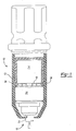
- a power tool 10 having a casing 12, motor 14, motor end plate 16 and an output device 18.
- the output device 18 generally includes a output device housing 20 that contains a planetary gear set to modify the input torque and rotational velocity from the motor to an output device, such as a screwdriver or other attachment head.
- Output shaft 30 (in Fig. 2) has a pinion 32 that acts as a sun gear for the planetary gear set of the output device 18.
- rotational energy transmitted from output shaft 30 is transmitted to planetary gears in the output device housing 20 and ultimately to the output device.
- Motor 14 is positioned within casing 12.
- Motor end plate 16 acts to connect motor 14 to output device 18. (As will be discussed).
- Tabs 34 extend into casing 12 for anchoring to maintain motor 14 and output device 18 in a fixed rotational position in the casing 12. It is noted that the tabs 34 could also extend from casing 12 into the end cap16.
- motor housing tabs 38 (only two of four motor housing tabs 38 shown in Fig. 2) engage cutout sections 40 of motor end plate 16. Once engaged, motor tabs 38 are bent over to lockingly adjoin motor end plate 16 to motor 14.
- the motor end plate 16 can be formed, molded or extruded as one unit with the remainder of the motor in a can shape, and the motor and end plate can be one piece as shown in Figure 6. However, the motor end plate still occupies the bottom portion of the motor.
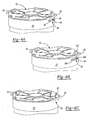
- FIG. 3A motor end plate 16 is shown having an output device attachment area 42.
- Output device attachment area 42 includes a base portion 44 disposed on a downward side of motor end plate 16, and a locking tab 46 extending radially outward from a center of motor end plate 16.
- locking tab 46 On an upper side of locking tab 46 is locking bump 48.
- output device attachment area 42 is positioned proximate tab 34.
- another output device attachment area 42 can be positioned approximately 180 degrees opposite the one shown and described in Fig. 3A. It is noted, however, that only one tab may be used as shown in the figure. In addition, three or more tabs may also be used, and each of the tabs can be positioned at any radial location and need not be positioned 180 degrees apart.
- output device housing 20 contains a motor end plate attachment area 50.
- Motor end plate attachment area 50 includes a downward slot portion 52 disposed in an axial direction on an axial face of output device housing 20.
- Circumferential slot portion 54 runs in a direction of the circumference of output device housing 20 and passes completely through the housing.
- Detent 56 is located at a predetermined position along circumferential slot portion 54.
- Locking tabs 46 are positioned on opposite sides of motor end plate 16, about 180 degrees from one another.
- the locking tabs can be formed by any known process, and can also be formed by stamping the tabs out of the relatively flat motor end plate.
- locking tabs 46 are moved downward into downward slot portion 52 until the face of the end cap abuts with the face of the output device housing.
- motor end plate 16 is rotated about its axis in a direction to move locking bump 48 toward detent 56.
- output device housing 20 can be rotated with respect to motor end plate 16, instead of the motor end plate being rotated.
- each output device attachment area 42 is shown with a respective locking tab 46 and locking bump 48.
- the motor 14 and output device housing 20 are positioned inside casing 12.
- each of the tabs 34 and 35 sit inside respective apertures 33 and 37. This acts to axially and radially support the motor and output device with casing 12, thereby helping to alleviate the force applied to motor end plate attachment area and the output device attachment area.
- only one tab and aperture need be used, and the two shown in the figure are preferred.
- output device attachment area 42 includes a locking tab 46a that has a locking bump 48a at the radial most outward position from the axial center of motor end plate 16.
- output device housing 20 has a downward slot portion 52 with a width to accommodate the width of locking tab 46a.
- Circumferential slot portion 52 is provided with detent 56a.
- Detent 56a is a vertical rod extending from a bottom surface of circumferential slot portion 54 to a top surface of circumferential slot portion 54.
- motor end plate 16 is positioned on the upper face of output device housing 20 to allow locking tab 46a to drop down into downward slot portion 52.
- motor end plate 16 is rotated in a direction to move locking bump 48a toward detent 56a. Interference exists between locking bumps 48a and detents 56a. This makes it difficult to rotate locking bumps 48a past detents 56a.
- a forced rotation of motor end plate 16 is required to move locking bumps 48a to a position past detents 56a. This ensures that motor end plate 16 remains in a locked position on output device housing 20. Reverse rotation in the opposite direction is required to release motor end plate 16. This rotation is also resisted by the interference between locking bumps 48a and detents 56a.
- motor end plate 16 has apertures 60 and is proximate tabs 34.
- Motor end plate attachment area 50 of output device housing 20 has barbed tabs 62.
- Barbed tabs 62 extend axially parallel to output device housing 20 and are attached to an inner surface of the output device. Accordingly, when motor end plate 16 is positioned downward onto an upper surface of output device housing 20, barbed tabs 62 interlocks with apertures 60 to maintain motor end plate 16 in a locked position with output device housing 20.
- the widths of locking bumps 48 and 48a and downward slot portions 52 can be different on opposite sides of the housing. More specifically, one slot portion 52 and corresponding locking bump can be very wide while the opposite slot portion and locking bump can be narrow. Thus, each locking bump only fits its respective slot portion.
- motor end plate 16 can be attached to output device housing 20 in one direction and not the other. In other words, motor end plate 16 is unable to be rotated 180 degrees and then attached to output device housing 20. This has significant manufacturing advantages. Specifically, if the motor and output device are required to be aligned in one angular direction, such a design will prohibit misalignment or improper assembly. Likewise, in the embodiment of fig.
- barb tabs 62 and apertures 60 can have different characteristics to ensure that motor end plate 16 is attached only one way to output device housing 20.
- motor end plate 16 can be detached from output device housing 20 very easily by simply rotating motor end plate 16 in a direction out of respective detents 56 and 56a.
- barb tab 62 on each 180 degree side is simply moved radially outward or likewise radially inward to allow walls of aperture 60 to slide thereover for removal of motor end plate 16. This has advantages for servicing the interior components of output device housing 20 and motor 14 after assembly.
- the motor end plate 16 attaches to the output device by using a quick connect/disconnect attachment mechanism. This allows the motor end plate 16 to detachably connect to the output device housing 20 by moving the motor endplate with respect to the output device. Specifically, in the embodiments of Fig. 3A and 3B, the motor endplate is pushed down and rotated to lock the two elements together. And, the reverse procedure is used to unlock. Likewise, in the embodiment of Fig. 3C, the motor endplate is pressed down until the barbed tabs 62 lock with apertures 60.
- the present invention operates by use of the quick connect/disconnect attachment by mere movement of the two elements with respect to one another. Further, it is noted that other quick connect/disconnect arrangements can be used that are not included in this description.
Landscapes
- Engineering & Computer Science (AREA)
- Mechanical Engineering (AREA)
- Motor Or Generator Frames (AREA)
- Connection Of Motors, Electrical Generators, Mechanical Devices, And The Like (AREA)
- Portable Nailing Machines And Staplers (AREA)
- Dry Shavers And Clippers (AREA)
- Operating, Guiding And Securing Of Roll- Type Closing Members (AREA)
Applications Claiming Priority (2)
| Application Number | Priority Date | Filing Date | Title |
|---|---|---|---|
| US36011 | 2001-12-27 | ||
| US10/036,011 US6672402B2 (en) | 2001-12-27 | 2001-12-27 | Combined fastenerless motor end cap and output device mounting |
Publications (3)
| Publication Number | Publication Date |
|---|---|
| EP1323501A2 true EP1323501A2 (de) | 2003-07-02 |
| EP1323501A3 EP1323501A3 (de) | 2007-09-19 |
| EP1323501B1 EP1323501B1 (de) | 2009-06-17 |
Family
ID=21886089
Family Applications (1)
| Application Number | Title | Priority Date | Filing Date |
|---|---|---|---|
| EP02027876A Expired - Lifetime EP1323501B1 (de) | 2001-12-27 | 2002-12-13 | Kombinierte befestigungsmittelfreie Verbindung eines Motorenddeckels und einer Abtriebsvorrichtung |
Country Status (10)
| Country | Link |
|---|---|
| US (1) | US6672402B2 (de) |
| EP (1) | EP1323501B1 (de) |
| JP (1) | JP4382491B2 (de) |
| CN (1) | CN1280973C (de) |
| AT (1) | ATE433838T1 (de) |
| AU (1) | AU2002357344A1 (de) |
| DE (1) | DE60232636D1 (de) |
| MX (1) | MXPA04006318A (de) |
| TW (1) | TWI281433B (de) |
| WO (1) | WO2003057415A1 (de) |
Cited By (9)
| Publication number | Priority date | Publication date | Assignee | Title |
|---|---|---|---|---|
| EP1642685A1 (de) * | 2004-09-30 | 2006-04-05 | HILTI Aktiengesellschaft | Bohr- und/oder Meisselhammer |
| EP1674215A1 (de) * | 2004-12-23 | 2006-06-28 | BLACK & DECKER INC. | Kraftwerkzeuggehäuse |
| WO2008145439A1 (de) * | 2007-05-25 | 2008-12-04 | Robert Bosch Gmbh | Elektrogerät |
| EP2082848A1 (de) * | 2008-01-24 | 2009-07-29 | Robert Bosch Gmbh | Elektrogerät mit Batteriepaket mit Mechanismus zur leichten Anbringung und Abnahme |
| US7705497B2 (en) | 2004-12-23 | 2010-04-27 | Black & Decker Inc. | Power tool cooling |
| WO2011137549A1 (de) * | 2010-05-03 | 2011-11-10 | Mueller Peter A | Koppelbarer antrieb |
| WO2012055651A3 (de) * | 2010-10-29 | 2012-07-05 | Robert Bosch Gmbh | Werkzeugmaschinenbremsvorrichtung |
| WO2012055647A3 (de) * | 2010-10-29 | 2012-07-05 | Robert Bosch Gmbh | Werkzeugmaschinenbremsvorrichtung |
| EP1811188B2 (de) † | 2006-01-18 | 2015-06-10 | Valeo Systèmes Thermiques | Vorrichtung zur Befestigung eines Aktuators und eines Gehäuses, insbesondere für ein Kraftfahrzeug |
Families Citing this family (27)
| Publication number | Priority date | Publication date | Assignee | Title |
|---|---|---|---|---|
| US7152695B2 (en) * | 2002-09-20 | 2006-12-26 | Snap-On Incorporated | Power tool with air seal and vibration dampener |
| JP4643298B2 (ja) | 2005-02-14 | 2011-03-02 | 株式会社マキタ | 打撃工具 |
| DE102005010793B4 (de) * | 2005-03-09 | 2016-11-10 | Robert Bosch Gmbh | Elektrohandwerkzeugmaschine |
| US7649337B2 (en) | 2005-05-17 | 2010-01-19 | Milwaukee Electric Tool Corporation | Power tool including a fuel gauge and method of operating the same |
| US7557534B2 (en) | 2005-05-17 | 2009-07-07 | Milwaukee Electric Tool Corporation | Power tool, battery, charger and method of operating the same |
| US7896103B2 (en) * | 2008-02-04 | 2011-03-01 | Ingersoll Rand Company | Power tool housing support structures |
| EP2421682B1 (de) * | 2009-04-20 | 2014-10-15 | Aesculap Suhl GmbH | Tierschermaschine |
| US8278803B2 (en) * | 2009-08-14 | 2012-10-02 | Lin Engineering | Motor end cap positioning element for maintaining rotor-stator concentricity |
| DE102009054640A1 (de) * | 2009-12-15 | 2011-06-16 | Robert Bosch Gmbh | Handwerkzeugmaschine |
| US8283841B2 (en) | 2010-06-23 | 2012-10-09 | Lin Engineering | Motor end cap with interference fit |
| EP2691214A4 (de) * | 2011-03-31 | 2016-03-09 | Ingersoll Rand Co | Twistlock-getriebegehäuse für elektrowerkzeuge |
| US9044850B2 (en) | 2011-07-27 | 2015-06-02 | Ingersoll-Rand Company | Twist lock gear case for power tools |
| GB2491194A (en) * | 2011-05-27 | 2012-11-28 | Norbar Torque Tools | Torque tool with synchronous reluctance motor |
| US9669535B2 (en) * | 2012-08-27 | 2017-06-06 | Ingersoll-Rand Company | Power tool housing construction |
| US9221156B2 (en) * | 2013-05-15 | 2015-12-29 | Snap-On Incorporated | Motorized hand tool apparatus and assembly method |
| DE102014225903A1 (de) | 2014-12-15 | 2016-06-16 | Robert Bosch Gmbh | Handwerkzeugvorrichtung |
| DE102015012960B4 (de) * | 2015-08-14 | 2021-09-16 | Franka Emika Gmbh | Robotersystem und Gehäuseteil für ein solches Robotersystem |
| US10632589B2 (en) * | 2016-08-29 | 2020-04-28 | Black & Decker Inc. | Power tool |
| EP3338959A1 (de) * | 2016-12-23 | 2018-06-27 | HILTI Aktiengesellschaft | Werkzeuggerät |
| EP3338957A1 (de) * | 2016-12-23 | 2018-06-27 | HILTI Aktiengesellschaft | Werkzeuggerät |
| WO2019001654A1 (en) * | 2017-06-28 | 2019-01-03 | Linak A/S | LINEAR ACTUATOR |
| US11813729B2 (en) | 2018-05-14 | 2023-11-14 | Black & Decker Inc. | Power tool with partition assembly between transmission and motor |
| US10971966B2 (en) | 2018-05-14 | 2021-04-06 | Black & Decker Inc. | Power tool with partition assembly between transmission and motor |
| EP3792005B1 (de) * | 2019-09-11 | 2023-06-07 | Robert Bosch GmbH | Handwerkzeugmaschine mit einem getriebeflansch |
| FR3112373B1 (fr) * | 2020-07-08 | 2023-04-21 | Innovaction Tech | Motoréducteur à enveloppe cylindrique et moteur tubulaire correspondant. |
| US12090606B2 (en) * | 2020-09-22 | 2024-09-17 | Snap-On Incorporated | Tool and motor anti-rotation |
| DE102022212839A1 (de) | 2022-11-30 | 2024-06-06 | Robert Bosch Gesellschaft mit beschränkter Haftung | Handwerkzeugmaschine |
Citations (2)
| Publication number | Priority date | Publication date | Assignee | Title |
|---|---|---|---|---|
| US4625134A (en) | 1985-03-25 | 1986-11-25 | Emhart Industries, Inc. | Means for mounting a gear train and motor |
| US5624000A (en) | 1994-07-26 | 1997-04-29 | Black & Decker, Inc. | Power tool with modular drive system and method of assembly of modular drive system |
Family Cites Families (23)
| Publication number | Priority date | Publication date | Assignee | Title |
|---|---|---|---|---|
| US3724237A (en) | 1971-06-07 | 1973-04-03 | Black & Decker Mfg Co | Attachment coupling for power tool |
| US4103511A (en) | 1976-10-04 | 1978-08-01 | Firma Kress Elektrik Gmbh & Co. | Connecting arrangement for a machine tool |
| US4093096A (en) | 1977-05-19 | 1978-06-06 | Societe Anonyme Dite: Arts Et Techniques Nouvelles | Removable stopper for a screw-neck bottle |
| IT1167912B (it) | 1981-06-05 | 1987-05-20 | Edi Bondioli | Protezione ad elementi componibili per alberi di trasmissione cardanici |
| FR2536372A1 (fr) | 1982-11-18 | 1984-05-25 | Mbf Plastiques | Systeme de retenue d'un obturateur ou capot par rapport au goulot d'un recipient |
| US4597453A (en) * | 1985-02-08 | 1986-07-01 | Cooper Industries, Inc. | Drive unit with self-aligning gearing system |
| DE59008112D1 (de) * | 1989-07-15 | 1995-02-09 | Kress Elektrik Gmbh & Co | Elektrowerkzeug. |
| US5033552A (en) | 1990-07-24 | 1991-07-23 | Hu Cheng Te | Multi-function electric tool |
| DE4126118A1 (de) | 1991-08-07 | 1993-02-11 | Swf Auto Electric Gmbh | Rastverbindung zwischen einem motortopf und einem getriebegehaeuse |
| US5251776A (en) | 1991-08-12 | 1993-10-12 | H. William Morgan, Jr. | Pressure vessel |
| US5347673A (en) | 1992-10-01 | 1994-09-20 | Black & Decker Inc. | Quick change pad assembly for orbital polisher |
| DE4235962C2 (de) | 1992-10-24 | 1997-11-27 | Temic Auto Electr Motors Gmbh | Elektromotor, insbesondere feuchtigkeitsdicht geschlossener Kommutatormotor mit einem axial angeflanschten Antriebsgehäuse |
| DE4422492A1 (de) | 1993-07-19 | 1995-01-26 | Teves Gmbh Alfred | Motor mit einem Umlaufgetriebe |
| US5409256A (en) | 1994-01-04 | 1995-04-25 | General Motors Corporation | Driver-side air bag module assembly |
| US5637104A (en) | 1995-06-15 | 1997-06-10 | Abbott Laboratories | Locking cap for the pour spout of a suction container |
| US5714815A (en) * | 1995-09-05 | 1998-02-03 | Mattel, Inc. | Motor mount assembly |
| DE19634502C2 (de) | 1996-08-26 | 1999-04-22 | Interelectric Ag | Elektromotor mit angebrachtem Zusatzelement |
| EP0847127B1 (de) | 1996-11-06 | 2000-03-15 | SAIA-Burgess Electronics AG | Elektroantrieb |
| US5722574A (en) | 1996-11-14 | 1998-03-03 | Ogio International, Inc. | Container and retaining apparatus |
| DE19729988C1 (de) | 1997-07-12 | 1998-08-13 | Buehler Gmbh Nachf Geb | Formschlüssige Verbindung zwischen einem aus Kunststoff bestehenden Getriebegehäuseteil und einer Adapterplatte eines Elektromotors |
| GB9718336D0 (en) * | 1997-08-30 | 1997-11-05 | Black & Decker Inc | Power tool |
| US6039126A (en) * | 1998-05-15 | 2000-03-21 | Hsieh; An-Fu | Multi-usage electric tool with angle-changeable grip |
| DE29820723U1 (de) | 1998-11-19 | 1999-02-25 | Mobiletron Electronics Co., Ltd., Ta-Ya Hsiang, Taichung | Bohrmaschinenstruktur für hohe Drehzahlen |
-
2001
- 2001-12-27 US US10/036,011 patent/US6672402B2/en not_active Expired - Fee Related
-
2002
- 2002-12-13 AT AT02027876T patent/ATE433838T1/de not_active IP Right Cessation
- 2002-12-13 DE DE60232636T patent/DE60232636D1/de not_active Expired - Lifetime
- 2002-12-13 EP EP02027876A patent/EP1323501B1/de not_active Expired - Lifetime
- 2002-12-18 AU AU2002357344A patent/AU2002357344A1/en not_active Abandoned
- 2002-12-18 WO PCT/US2002/040709 patent/WO2003057415A1/en not_active Ceased
- 2002-12-18 MX MXPA04006318A patent/MXPA04006318A/es active IP Right Grant
- 2002-12-18 JP JP2003557758A patent/JP4382491B2/ja not_active Expired - Fee Related
- 2002-12-23 TW TW091137014A patent/TWI281433B/zh not_active IP Right Cessation
- 2002-12-27 CN CN02159399.XA patent/CN1280973C/zh not_active Expired - Fee Related
Patent Citations (2)
| Publication number | Priority date | Publication date | Assignee | Title |
|---|---|---|---|---|
| US4625134A (en) | 1985-03-25 | 1986-11-25 | Emhart Industries, Inc. | Means for mounting a gear train and motor |
| US5624000A (en) | 1994-07-26 | 1997-04-29 | Black & Decker, Inc. | Power tool with modular drive system and method of assembly of modular drive system |
Cited By (14)
| Publication number | Priority date | Publication date | Assignee | Title |
|---|---|---|---|---|
| EP1642685A1 (de) * | 2004-09-30 | 2006-04-05 | HILTI Aktiengesellschaft | Bohr- und/oder Meisselhammer |
| EP1674215A1 (de) * | 2004-12-23 | 2006-06-28 | BLACK & DECKER INC. | Kraftwerkzeuggehäuse |
| US7705497B2 (en) | 2004-12-23 | 2010-04-27 | Black & Decker Inc. | Power tool cooling |
| EP1811188B2 (de) † | 2006-01-18 | 2015-06-10 | Valeo Systèmes Thermiques | Vorrichtung zur Befestigung eines Aktuators und eines Gehäuses, insbesondere für ein Kraftfahrzeug |
| RU2467868C2 (ru) * | 2007-05-25 | 2012-11-27 | Роберт Бош Гмбх | Электрический аппарат |
| WO2008145439A1 (de) * | 2007-05-25 | 2008-12-04 | Robert Bosch Gmbh | Elektrogerät |
| DE102007024387B4 (de) | 2007-05-25 | 2026-05-07 | Robert Bosch Gmbh | Elektrowerkzeug |
| EP2082848A1 (de) * | 2008-01-24 | 2009-07-29 | Robert Bosch Gmbh | Elektrogerät mit Batteriepaket mit Mechanismus zur leichten Anbringung und Abnahme |
| US8163414B2 (en) | 2008-01-24 | 2012-04-24 | Robert Bosch Gmbh | Electrical device having a battery pack with an easy attachment and release mechanism |
| US9416864B2 (en) | 2010-05-03 | 2016-08-16 | Peter A. Mueller | Coupleable drive |
| WO2011137549A1 (de) * | 2010-05-03 | 2011-11-10 | Mueller Peter A | Koppelbarer antrieb |
| WO2012055647A3 (de) * | 2010-10-29 | 2012-07-05 | Robert Bosch Gmbh | Werkzeugmaschinenbremsvorrichtung |
| WO2012055651A3 (de) * | 2010-10-29 | 2012-07-05 | Robert Bosch Gmbh | Werkzeugmaschinenbremsvorrichtung |
| US9243674B2 (en) | 2010-10-29 | 2016-01-26 | Robert Bosch Gmbh | Power tool braking device |
Also Published As
| Publication number | Publication date |
|---|---|
| MXPA04006318A (es) | 2004-10-04 |
| JP2005514891A (ja) | 2005-05-19 |
| US6672402B2 (en) | 2004-01-06 |
| AU2002357344A1 (en) | 2003-07-24 |
| US20030121676A1 (en) | 2003-07-03 |
| CN1280973C (zh) | 2006-10-18 |
| WO2003057415A1 (en) | 2003-07-17 |
| TW200301725A (en) | 2003-07-16 |
| JP4382491B2 (ja) | 2009-12-16 |
| TWI281433B (en) | 2007-05-21 |
| DE60232636D1 (de) | 2009-07-30 |
| CN1428919A (zh) | 2003-07-09 |
| EP1323501B1 (de) | 2009-06-17 |
| EP1323501A3 (de) | 2007-09-19 |
| ATE433838T1 (de) | 2009-07-15 |
Similar Documents
| Publication | Publication Date | Title |
|---|---|---|
| US6672402B2 (en) | Combined fastenerless motor end cap and output device mounting | |
| JP6452178B2 (ja) | サーボモータ及びロボット | |
| US20130047762A1 (en) | Switchable gear drive for a handheld power tool | |
| DE602006000984T2 (de) | Elektrische Scheibenbremse für ein Fahrzeug | |
| DE112013006302T5 (de) | Leistungsübertragungseinheit für Fahrzeug | |
| CN101495348B (zh) | 抬升装置 | |
| JP2003507661A (ja) | ワンウエイクラッチ及びその製造方法 | |
| JP6362628B2 (ja) | ワンウェイクラッチキャリアアセンブリ | |
| EP3081833B1 (de) | Öldichtungskappe und exzentrisch schwingende getriebevorrichtung damit | |
| US8540066B2 (en) | Rotationally fixed connection of two parts of a transmission for transmitting torque | |
| JP2011511226A (ja) | 改良されたディファレンシャル用ホールドアウトリングの構造 | |
| US6452296B1 (en) | Motor device and transmission mechanism | |
| EP1253336A1 (de) | Keilnutkupplung für ein räumlich begrenztes Umfeld und Verfahren zum Montieren und Demontieren | |
| JP2019060425A (ja) | 減速機付モータ | |
| JP3490162B2 (ja) | 変速機の回転部材結合構造 | |
| JP4207028B2 (ja) | 内燃機関始動回転力伝達機構及び内燃機関強制回転駆動試験方法 | |
| JP2005163804A (ja) | 回転軸継手 | |
| JP3202209B2 (ja) | 多板クラッチのためのケーシング及び多板クラッチ | |
| EP3489546B1 (de) | Planetenuntersetzungsgetriebe für extrem schnelle reduktion | |
| JP5880814B2 (ja) | 摺動式スプライン軸装置およびその製造方法 | |
| JP4316196B2 (ja) | 差動制限装置 | |
| JP3991578B2 (ja) | 特殊デフ装置の組立方法および同方法に用いられる治具 | |
| US7748504B2 (en) | Hydraulic servo for a brake in an automatic transmission | |
| CN112555385A (zh) | 齿轮箱组件及其蜗杆轴组件 | |
| US8083473B2 (en) | Interface for a stamped stator and a one-way clutch |
Legal Events
| Date | Code | Title | Description |
|---|---|---|---|
| PUAI | Public reference made under article 153(3) epc to a published international application that has entered the european phase |
Free format text: ORIGINAL CODE: 0009012 |
|
| AK | Designated contracting states |
Designated state(s): AT BE BG CH CY CZ DE DK EE ES FI FR GB GR IE IT LI LU MC NL PT SE SI SK TR |
|
| AX | Request for extension of the european patent |
Extension state: AL LT LV MK RO |
|
| PUAL | Search report despatched |
Free format text: ORIGINAL CODE: 0009013 |
|
| AK | Designated contracting states |
Kind code of ref document: A3 Designated state(s): AT BE BG CH CY CZ DE DK EE ES FI FR GB GR IE IT LI LU MC NL PT SE SI SK TR |
|
| AX | Request for extension of the european patent |
Extension state: AL LT LV MK RO |
|
| 17P | Request for examination filed |
Effective date: 20070928 |
|
| 17Q | First examination report despatched |
Effective date: 20080312 |
|
| AKX | Designation fees paid |
Designated state(s): AT BE BG CH CY CZ DE DK EE ES FI FR GB GR IE IT LI LU MC NL PT SE SI SK TR |
|
| GRAP | Despatch of communication of intention to grant a patent |
Free format text: ORIGINAL CODE: EPIDOSNIGR1 |
|
| GRAS | Grant fee paid |
Free format text: ORIGINAL CODE: EPIDOSNIGR3 |
|
| GRAA | (expected) grant |
Free format text: ORIGINAL CODE: 0009210 |
|
| AK | Designated contracting states |
Kind code of ref document: B1 Designated state(s): AT BE BG CH CY CZ DE DK EE ES FI FR GB GR IE IT LI LU MC NL PT SE SI SK TR |
|
| REG | Reference to a national code |
Ref country code: GB Ref legal event code: FG4D |
|
| REG | Reference to a national code |
Ref country code: CH Ref legal event code: EP |
|
| REG | Reference to a national code |
Ref country code: IE Ref legal event code: FG4D |
|
| REF | Corresponds to: |
Ref document number: 60232636 Country of ref document: DE Date of ref document: 20090730 Kind code of ref document: P |
|
| PG25 | Lapsed in a contracting state [announced via postgrant information from national office to epo] |
Ref country code: FI Free format text: LAPSE BECAUSE OF FAILURE TO SUBMIT A TRANSLATION OF THE DESCRIPTION OR TO PAY THE FEE WITHIN THE PRESCRIBED TIME-LIMIT Effective date: 20090617 Ref country code: AT Free format text: LAPSE BECAUSE OF FAILURE TO SUBMIT A TRANSLATION OF THE DESCRIPTION OR TO PAY THE FEE WITHIN THE PRESCRIBED TIME-LIMIT Effective date: 20090617 |
|
| PG25 | Lapsed in a contracting state [announced via postgrant information from national office to epo] |
Ref country code: SE Free format text: LAPSE BECAUSE OF FAILURE TO SUBMIT A TRANSLATION OF THE DESCRIPTION OR TO PAY THE FEE WITHIN THE PRESCRIBED TIME-LIMIT Effective date: 20090917 Ref country code: SI Free format text: LAPSE BECAUSE OF FAILURE TO SUBMIT A TRANSLATION OF THE DESCRIPTION OR TO PAY THE FEE WITHIN THE PRESCRIBED TIME-LIMIT Effective date: 20090617 |
|
| NLV1 | Nl: lapsed or annulled due to failure to fulfill the requirements of art. 29p and 29m of the patents act | ||
| PG25 | Lapsed in a contracting state [announced via postgrant information from national office to epo] |
Ref country code: ES Free format text: LAPSE BECAUSE OF FAILURE TO SUBMIT A TRANSLATION OF THE DESCRIPTION OR TO PAY THE FEE WITHIN THE PRESCRIBED TIME-LIMIT Effective date: 20090928 Ref country code: EE Free format text: LAPSE BECAUSE OF FAILURE TO SUBMIT A TRANSLATION OF THE DESCRIPTION OR TO PAY THE FEE WITHIN THE PRESCRIBED TIME-LIMIT Effective date: 20090617 Ref country code: CZ Free format text: LAPSE BECAUSE OF FAILURE TO SUBMIT A TRANSLATION OF THE DESCRIPTION OR TO PAY THE FEE WITHIN THE PRESCRIBED TIME-LIMIT Effective date: 20090617 |
|
| PG25 | Lapsed in a contracting state [announced via postgrant information from national office to epo] |
Ref country code: SK Free format text: LAPSE BECAUSE OF FAILURE TO SUBMIT A TRANSLATION OF THE DESCRIPTION OR TO PAY THE FEE WITHIN THE PRESCRIBED TIME-LIMIT Effective date: 20090617 Ref country code: NL Free format text: LAPSE BECAUSE OF FAILURE TO SUBMIT A TRANSLATION OF THE DESCRIPTION OR TO PAY THE FEE WITHIN THE PRESCRIBED TIME-LIMIT Effective date: 20090617 Ref country code: BE Free format text: LAPSE BECAUSE OF FAILURE TO SUBMIT A TRANSLATION OF THE DESCRIPTION OR TO PAY THE FEE WITHIN THE PRESCRIBED TIME-LIMIT Effective date: 20090617 |
|
| PG25 | Lapsed in a contracting state [announced via postgrant information from national office to epo] |
Ref country code: BG Free format text: LAPSE BECAUSE OF FAILURE TO SUBMIT A TRANSLATION OF THE DESCRIPTION OR TO PAY THE FEE WITHIN THE PRESCRIBED TIME-LIMIT Effective date: 20090917 Ref country code: PT Free format text: LAPSE BECAUSE OF FAILURE TO SUBMIT A TRANSLATION OF THE DESCRIPTION OR TO PAY THE FEE WITHIN THE PRESCRIBED TIME-LIMIT Effective date: 20091017 |
|
| PLBE | No opposition filed within time limit |
Free format text: ORIGINAL CODE: 0009261 |
|
| STAA | Information on the status of an ep patent application or granted ep patent |
Free format text: STATUS: NO OPPOSITION FILED WITHIN TIME LIMIT |
|
| PG25 | Lapsed in a contracting state [announced via postgrant information from national office to epo] |
Ref country code: DK Free format text: LAPSE BECAUSE OF FAILURE TO SUBMIT A TRANSLATION OF THE DESCRIPTION OR TO PAY THE FEE WITHIN THE PRESCRIBED TIME-LIMIT Effective date: 20090617 |
|
| 26N | No opposition filed |
Effective date: 20100318 |
|
| PG25 | Lapsed in a contracting state [announced via postgrant information from national office to epo] |
Ref country code: MC Free format text: LAPSE BECAUSE OF NON-PAYMENT OF DUE FEES Effective date: 20100701 |
|
| REG | Reference to a national code |
Ref country code: CH Ref legal event code: PL |
|
| REG | Reference to a national code |
Ref country code: FR Ref legal event code: ST Effective date: 20100831 |
|
| PG25 | Lapsed in a contracting state [announced via postgrant information from national office to epo] |
Ref country code: IE Free format text: LAPSE BECAUSE OF NON-PAYMENT OF DUE FEES Effective date: 20091213 Ref country code: GR Free format text: LAPSE BECAUSE OF FAILURE TO SUBMIT A TRANSLATION OF THE DESCRIPTION OR TO PAY THE FEE WITHIN THE PRESCRIBED TIME-LIMIT Effective date: 20090918 Ref country code: FR Free format text: LAPSE BECAUSE OF NON-PAYMENT OF DUE FEES Effective date: 20091231 Ref country code: CH Free format text: LAPSE BECAUSE OF NON-PAYMENT OF DUE FEES Effective date: 20091231 Ref country code: LI Free format text: LAPSE BECAUSE OF NON-PAYMENT OF DUE FEES Effective date: 20091231 |
|
| PG25 | Lapsed in a contracting state [announced via postgrant information from national office to epo] |
Ref country code: IT Free format text: LAPSE BECAUSE OF FAILURE TO SUBMIT A TRANSLATION OF THE DESCRIPTION OR TO PAY THE FEE WITHIN THE PRESCRIBED TIME-LIMIT Effective date: 20090617 |
|
| PG25 | Lapsed in a contracting state [announced via postgrant information from national office to epo] |
Ref country code: LU Free format text: LAPSE BECAUSE OF NON-PAYMENT OF DUE FEES Effective date: 20091213 |
|
| PG25 | Lapsed in a contracting state [announced via postgrant information from national office to epo] |
Ref country code: TR Free format text: LAPSE BECAUSE OF FAILURE TO SUBMIT A TRANSLATION OF THE DESCRIPTION OR TO PAY THE FEE WITHIN THE PRESCRIBED TIME-LIMIT Effective date: 20090617 |
|
| PG25 | Lapsed in a contracting state [announced via postgrant information from national office to epo] |
Ref country code: CY Free format text: LAPSE BECAUSE OF FAILURE TO SUBMIT A TRANSLATION OF THE DESCRIPTION OR TO PAY THE FEE WITHIN THE PRESCRIBED TIME-LIMIT Effective date: 20090617 |
|
| PGFP | Annual fee paid to national office [announced via postgrant information from national office to epo] |
Ref country code: DE Payment date: 20151208 Year of fee payment: 14 Ref country code: GB Payment date: 20151209 Year of fee payment: 14 |
|
| REG | Reference to a national code |
Ref country code: DE Ref legal event code: R119 Ref document number: 60232636 Country of ref document: DE |
|
| GBPC | Gb: european patent ceased through non-payment of renewal fee |
Effective date: 20161213 |
|
| PG25 | Lapsed in a contracting state [announced via postgrant information from national office to epo] |
Ref country code: GB Free format text: LAPSE BECAUSE OF NON-PAYMENT OF DUE FEES Effective date: 20161213 Ref country code: DE Free format text: LAPSE BECAUSE OF NON-PAYMENT OF DUE FEES Effective date: 20170701 |