EP1323909A2 - Compresseur à suralimentation - Google Patents
Compresseur à suralimentation Download PDFInfo
- Publication number
- EP1323909A2 EP1323909A2 EP02028489A EP02028489A EP1323909A2 EP 1323909 A2 EP1323909 A2 EP 1323909A2 EP 02028489 A EP02028489 A EP 02028489A EP 02028489 A EP02028489 A EP 02028489A EP 1323909 A2 EP1323909 A2 EP 1323909A2
- Authority
- EP
- European Patent Office
- Prior art keywords
- supercharger
- roller
- traction
- speed increasing
- center roller
- Prior art date
- Legal status (The legal status is an assumption and is not a legal conclusion. Google has not performed a legal analysis and makes no representation as to the accuracy of the status listed.)
- Withdrawn
Links
Images


Classifications
-
- F—MECHANICAL ENGINEERING; LIGHTING; HEATING; WEAPONS; BLASTING
- F02—COMBUSTION ENGINES; HOT-GAS OR COMBUSTION-PRODUCT ENGINE PLANTS
- F02B—INTERNAL-COMBUSTION PISTON ENGINES; COMBUSTION ENGINES IN GENERAL
- F02B33/00—Engines characterised by provision of pumps for charging or scavenging
- F02B33/32—Engines with pumps other than of reciprocating-piston type
- F02B33/34—Engines with pumps other than of reciprocating-piston type with rotary pumps
-
- F—MECHANICAL ENGINEERING; LIGHTING; HEATING; WEAPONS; BLASTING
- F01—MACHINES OR ENGINES IN GENERAL; ENGINE PLANTS IN GENERAL; STEAM ENGINES
- F01D—NON-POSITIVE DISPLACEMENT MACHINES OR ENGINES, e.g. STEAM TURBINES
- F01D5/00—Blades; Blade-carrying members; Heating, heat-insulating, cooling or antivibration means on the blades or the members
- F01D5/02—Blade-carrying members, e.g. rotors
- F01D5/026—Shaft to shaft connections
-
- F—MECHANICAL ENGINEERING; LIGHTING; HEATING; WEAPONS; BLASTING
- F02—COMBUSTION ENGINES; HOT-GAS OR COMBUSTION-PRODUCT ENGINE PLANTS
- F02B—INTERNAL-COMBUSTION PISTON ENGINES; COMBUSTION ENGINES IN GENERAL
- F02B39/00—Component parts, details, or accessories relating to, driven charging or scavenging pumps, not provided for in groups F02B33/00 - F02B37/00
- F02B39/02—Drives of pumps; Varying pump drive gear ratio
- F02B39/04—Mechanical drives; Variable-gear-ratio drives
-
- F—MECHANICAL ENGINEERING; LIGHTING; HEATING; WEAPONS; BLASTING
- F02—COMBUSTION ENGINES; HOT-GAS OR COMBUSTION-PRODUCT ENGINE PLANTS
- F02C—GAS-TURBINE PLANTS; AIR INTAKES FOR JET-PROPULSION PLANTS; CONTROLLING FUEL SUPPLY IN AIR-BREATHING JET-PROPULSION PLANTS
- F02C6/00—Plural gas-turbine plants; Combinations of gas-turbine plants with other apparatus; Adaptations of gas-turbine plants for special use
- F02C6/04—Gas-turbine plants providing heated or pressurised working fluid for other apparatus, e.g. without mechanical power output
- F02C6/10—Gas-turbine plants providing heated or pressurised working fluid for other apparatus, e.g. without mechanical power output supplying working fluid to a user, e.g. a chemical process, which returns working fluid to a turbine of the plant
- F02C6/12—Turbochargers, i.e. plants for augmenting mechanical power output of internal-combustion piston engines by increase of charge pressure
-
- F—MECHANICAL ENGINEERING; LIGHTING; HEATING; WEAPONS; BLASTING
- F04—POSITIVE - DISPLACEMENT MACHINES FOR LIQUIDS; PUMPS FOR LIQUIDS OR ELASTIC FLUIDS
- F04D—NON-POSITIVE-DISPLACEMENT PUMPS
- F04D25/00—Pumping installations or systems
- F04D25/02—Units comprising pumps and their driving means
- F04D25/024—Units comprising pumps and their driving means the driving means being assisted by a power recovery turbine
-
- F—MECHANICAL ENGINEERING; LIGHTING; HEATING; WEAPONS; BLASTING
- F16—ENGINEERING ELEMENTS AND UNITS; GENERAL MEASURES FOR PRODUCING AND MAINTAINING EFFECTIVE FUNCTIONING OF MACHINES OR INSTALLATIONS; THERMAL INSULATION IN GENERAL
- F16H—GEARING
- F16H13/00—Gearing for conveying rotary motion with constant gear ratio by friction between rotary members
- F16H13/02—Gearing for conveying rotary motion with constant gear ratio by friction between rotary members without members having orbital motion
- F16H13/04—Gearing for conveying rotary motion with constant gear ratio by friction between rotary members without members having orbital motion with balls or with rollers acting in a similar manner
-
- F—MECHANICAL ENGINEERING; LIGHTING; HEATING; WEAPONS; BLASTING
- F05—INDEXING SCHEMES RELATING TO ENGINES OR PUMPS IN VARIOUS SUBCLASSES OF CLASSES F01-F04
- F05D—INDEXING SCHEME FOR ASPECTS RELATING TO NON-POSITIVE-DISPLACEMENT MACHINES OR ENGINES, GAS-TURBINES OR JET-PROPULSION PLANTS
- F05D2220/00—Application
- F05D2220/40—Application in turbochargers
-
- F—MECHANICAL ENGINEERING; LIGHTING; HEATING; WEAPONS; BLASTING
- F05—INDEXING SCHEMES RELATING TO ENGINES OR PUMPS IN VARIOUS SUBCLASSES OF CLASSES F01-F04
- F05D—INDEXING SCHEME FOR ASPECTS RELATING TO NON-POSITIVE-DISPLACEMENT MACHINES OR ENGINES, GAS-TURBINES OR JET-PROPULSION PLANTS
- F05D2260/00—Function
- F05D2260/40—Transmission of power
- F05D2260/403—Transmission of power through the shape of the drive components
- F05D2260/4031—Transmission of power through the shape of the drive components as in toothed gearing
- F05D2260/40311—Transmission of power through the shape of the drive components as in toothed gearing of the epicyclical, planetary or differential type
-
- F—MECHANICAL ENGINEERING; LIGHTING; HEATING; WEAPONS; BLASTING
- F16—ENGINEERING ELEMENTS AND UNITS; GENERAL MEASURES FOR PRODUCING AND MAINTAINING EFFECTIVE FUNCTIONING OF MACHINES OR INSTALLATIONS; THERMAL INSULATION IN GENERAL
- F16H—GEARING
- F16H13/00—Gearing for conveying rotary motion with constant gear ratio by friction between rotary members
- F16H13/10—Means for influencing the pressure between the members
- F16H13/14—Means for influencing the pressure between the members for automatically varying the pressure mechanically
Definitions
- the present invention relates to a supercharger.
- Japanese Patent Application Laid-Open No. 4-203421 proposes a structure using a planetary gear mechanism and Japanese Patent Publication No. 11-502596 proposes a structure using a planetary friction roller mechanism, as the speed increasing gear.
- An object of the present invention is to produce a supercharger which does not generate a slip at high speed rotation and a driving loss at low speed rotation, which has low noise and low vibration, which has a light weight and a compact size, and which can be produced at a high productivity.
- Another object of the present invention is to improve lubricating and cooling performances of a bearing portion in an output shaft, so as to make it possible to adjust a thrust load and improve durability.
- a supercharger in which a rotation speed of an input shaft is increased by a speed increasing gear of the traction roller type so as to be transmitted to an output shaft, and wherein an impeller is provided in the output shaft.
- the speed increasing gear of the traction roller type comprises a center roller connected to the output shaft; an outer ring arranged eccentric to the center roller; and a plurality of intermediate rollers arranged within an annular space in which a width of the center roller with respect to a diametrical direction is uneven with respect to a circumferential direction of the center roller.
- the annular space is provided between a driven side cylindrical surface corresponding to an outer circumferential surface of the center roller and a drive side cylindrical surface corresponding to an inner circumferential surface of the outer ring.
- Respective outer circumferential surfaces of the intermediate rollers are formed as power transmitting cylindrical surfaces.
- a pivot of at least one intermediate roller is movably arranged in a circumferential direction and a radial direction of the center roller.
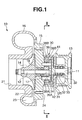
- An automotive supercharger 10 in FIG. 1 comprises an input shaft 11, a speed increasing gear of the traction roller type 30 that transmits increased rotation to an output shaft 12, a pulley 13 driven by an engine output and fixed to the input shaft 11, and an impeller 14 provided in the output shaft 12.
- the supercharger 10 is structured such that a compressor housing 16 is fixed to a center plate 15.
- the center plate 15 supports the output shaft 12 by a bearing 17.
- Reference numeral 18 denotes an oil seal.
- the compressor housing 16 receives the impeller 14, and is provided with a suction port 21, a supercharging passage 22 and a scroll 23.
- the speed increasing gear of the traction roller type 30 is a traction roller type speed increasing gear utilizing a wedge effect, and is provided with a speed increasing housing 31 in such a manner as to be fixed to the center plate 15, and the speed increasing housing 31 supports the input shaft 11 by a bearing 32.
- Reference numeral 33 denotes an oil seal.
- the speed increasing gear of the traction roller type 30 is provided with a center roller 34 integrally and concentrically arranged in an end portion of the output shaft 12, in an inner portion of the speed increasing housing 31.
- the speed increasing gear of the traction roller type 30 is provided with an outer ring 36 integrally and concentrically arranged in an end portion of the input shaft 11 via a disc portion 35, in the inner portion of the speed increasing housing 31.
- An outer ring 36 is arranged eccentric to the center roller 34.
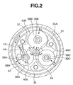
- three intermediate rollers 38A to 38C are arranged within an annular space 37 in which a width of the center roller 34 with respect to a radial direction is uneven with respect to a circumferential direction of the center roller 34 due to the eccentricity between the center roller 34 and the outer ring 36.
- the annular space 37 is provided between a driven side cylindrical surface 34A corresponding to an outer circumferential surface of the center roller 34 and a drive side cylindrical surface 36A corresponding to an inner circumferential surface of the outer ring 36, in the inner portion of the speed increasing housing 31.
- the end portions of three pivots 39A to 39C are respectively supported on the center plate 15 and a connection plate 41.
- connection plate 41 is fixed to the center plate 15 by connection bolts 41A (FIG. 4) and is received at a position in the inner portion of the speed increasing housing 31 and along the disc portion 35.
- the intermediate rollers 38A to 38C are rotatably supported by the pivots 39A to 39C, respectively.
- the respective pivots 39A to 39C are arranged parallel to the center roller 34 and a center axis of the outer ring 36.
- outer circumferential surfaces thereof are formed as power transmitting cylindrical surfaces 40A to 40C which roll in contact with the driven side cylindrical surface 34A of the center roller 34 and the drive side cylindrical surface 36A of the outer ring 36.
- pivots 39B and 39C are fixed by pressing or inserting both end portions thereof into supporting holes provided in the center plate 15 and the connection plate 41 with no play. Accordingly, the pivots 39B and 39C do not displace in a circumferential direction and a radial direction of the center roller 34 in the inner portion of the speed increasing housing 31.
- the pivot 39A is structured such that both end portions thereof can freely displace in the circumferential direction and the radial direction of the center roller 34 within the center plate 15 and a guide groove 42 provided in the connection plate 41, and the intermediate roller 38A is formed as a movable roller.
- the pivot 39A is pressed by a spring 44 corresponding to a pressing means which is backed up by a spring receiver 43 provided in the center plate 15 or the connection plate 41, and presses the movable roller 38A corresponding to the intermediate roller to the center roller 34 and the outer ring 36 in a direction in which a width of the annular space 37 becomes narrow.
- the movable roller 38A moves in a direction b in which the movable roller 38A is exposed to the wedge effect between the outer ring 36 and the center roller 34 according to a rotation of the outer ring 36 in a direction a , so that a pressing force c is generated among the driven side cylindrical surface 34A of the center roller 34, the drive side cylindrical surface 36A of the outer ring 36 and the power transmitting cylindrical surfaces 40A to 40C of the intermediate rollers 38A to 38C.
- a friction force is generated among the driven side cylindrical surface 34A of the center roller 34, the drive side cylindrical surface 36A of the outer ring 36 and the power transmitting cylindrical surfaces 40A to 40C of the intermediate rollers 38A to 38C.
- the driving force transmitted to the outer ring 36 is transmitted to the center roller 34, and the center roller 34 rotates in a direction d .
- the rotation of the center roller 34 generates a rotation of the integrally formed output shaft 12.
- the impeller 14 fixed to the output shaft rotates, and air is sucked from the suction port 21. This air is supercharged so as to be supplied to the engine from a chamber pipe communicated with the scroll 23.
- the movable roller 38A displaces in an opposite direction to the direction b , a connection between the drive side cylindrical surface 36A of the outer ring 36 and the power transmitting cylindrical surface 40A of the movable roller 38A is shut off, and a power transmission between the outer ring 36 and the movable roller 38A is shut off.
- the intermediate roller 38C is formed as the movable roller in the same manner as the intermediate roller 38A, and the movable rollers 38A and 38C are structured such as to be opposed to each other with respect to the narrow portion of the annular space 37 so as to be pressed displaceably within the guide grooves 42 by attached springs 44 and 44, as shown in FIG. 3.
- a stopper (not shown) for preventing the movable roller 38C (or 38A) on the opposite side to the movable roller 38A (or 38C) generating the wedge effect from escaping in a direction coming off from the wedge may be attached to the pivots 39A and 39C of the movable roller 38A and 38C.
- a distance at which the movable roller 38A can displace in the direction b is regulated by a length of the guide groove 42. Accordingly, when the outer ring 36 rotates in the direction a , it is possible to limit the pressing force c which is generated by the wedge effect applied to the movable roller 38A between the movable roller 38A and the center roller 34. In the case shown in FIG. 3 that the power transmission is performed without relation to the direction of the driving force input to the outer ring 36, it is possible to achieve limiting in the same manner. It is thus possible to limit a supercharging pressure and an air volume which the supercharger 10 can supply.
- Traction oil is sealed in the annular space 37 of the speed increasing gear of the traction roller type 30, and the traction oil lubricates and cools portions such as the driven side cylindrical surface 34A of the center roller 34, the drive side cylindrical surface 36A of the outer ring 36, the power transmitting cylindrical surfaces 40A to 40C of the intermediate rollers 38A to 38C, the bearing 17 of the output shaft 12 and the like.
- the traction oil may be forcibly circulated to these portions by an oil pump provided in an inner portion or an outer portion of the speed increasing gear of the traction roller type 30.
- an oil passage 46 communicating an outer circumferential portion of a space within the speed increasing gear of the traction roller type 30 with a space 45 held between the bearing 17 and the oil seal 18 can be pierced in the center plate 15, and the traction oil around the drive side cylindrical surface 36A of the outer ring 36 near an inner wall of the speed increasing housing 31 thrown up based on the rotation of the speed increasing gear of the traction roller type 30 can be received by an oil receiving portion 36B.
- the traction oil can be introduced to the bearing 17 from the oil passage 46 through the oil receiving portion 36B, and the traction oil can then flow out to the driven side cylindrical surface 34A of the center roller 34.
- the traction oil can be further guided to the power transmitting cylindrical surfaces 40A to 40C of the intermediate rollers 38A to 38C, and the traction oil can be circulated to portions to be lubricated such as the driven side cylindrical surface 34A of the center roller 34, the drive side cylindrical surface 36A of the outer ring 36, the power transmitting cylindrical surfaces 40A to 40C of the intermediate rollers 38A to 38C, the bearing 17 of the output shaft 12 and the like.
- a supercharger 10 according to a second embodiment is different from the supercharger 10 according to the first embodiment in that the speed increasing gear of the traction roller type 30 is provided with a built-in oil pump 50; such as a trochoidal pump or a vane pump, and so on, for circulating the traction oil in the inner portion of the speed increasing gear of the traction roller type 30.
- a built-in oil pump 50 such as a trochoidal pump or a vane pump, and so on
- the oil pump 50 comprises an outer rotor 51 assembled in the speed increasing housing 31, and an inner rotor 52 connected by such as spline-connection, and so on, to the input shaft 11.
- the oil pump 50 circulates the traction oil sealed in the speed increasing housing 31 to an external portion so as to cool, and again introduces the traction oil into the inner portion of the speed increasing housing 31, whereby it is possible to lubricate and cool the driven side cylindrical surface 34A of the center roller 34, the drive side cylindrical surface 36A of the outer ring 36, and the power transmitting cylindrical surfaces 40A to 40C of the intermediate rollers 38A to 38C.
- the oil pump 50 can supply the circulating traction oil to the bearing 17 of the output shaft 12 from an oil passage 53 provided in the center plate 15 via an oil feeding pipe (not shown) through an oil hole 54, and can flow out the oil to the driven side cylindrical surface 34A of the center roller 34, and the power transmitting cylindrical surfaces 40A to 40C of the intermediate rollers 38A to 38C.
- the oil pump 50 for lubricating and cooling the bearing 17 of the output shaft 12 and the contact surfaces among the outer ring 36, the intermediate rollers 38A to 38C and the center roller 34 is provided in the inner portion of the supercharger 10. Therefore, there is no need that the oil pump 50 is arranged in the outer portion of the supercharger 10 as in the conventional case, and it is possible to achieve a compact structure.
- a supercharger 10 according to a third embodiment is different from the superchargers 10 according to the first embodiment and the second embodiment in that an electromagnetic clutch 60 is provided between the input shaft 11 and the pulley 13, and the electromagnetic clutch 60 can be controlled to be turned on and off in correspondence with whether or not supercharging by the supercharger 10 is required.
- the electromagnetic clutch 60 can employ a disc type clutch, a powder clutch and the like.
- the electromagnetic clutch 60 can employ a structure having a small capacity. Accordingly, even in the case that the electromagnetic clutch 60 is mounted, the supercharger can be easily mounted to the engine in comparison with conventional mechanical superchargers.
- a supercharger 10 according to a fourth embodiment is different from the superchargers 10 according to the first embodiment, second embodiment and third embodiment in that a balance plate 70 is provided in the output shaft 12.
- a supercharging pressure is introduced into a space 71 in one side of the balance plate 70 from the scroll 23 via a passage 72.
- a suction pressure (or an atmospheric pressure from an atmospheric space) is introduced into a space 73 in another side of the balance plate 70 from a suction port 71 via a passage 74. Pressures in both of the spaces 71 and 73 applied to the balance plate 70 balance a thrust load applied to the impeller 14, and reduce a thrust load applied to the bearing 17 of the output shaft 12.
- the balance plate 70 since the balance plate 70 is provided in the output shaft 12, the supercharging pressure is applied to one side of the balance plate 70, and the suction pressure or the atmospheric pressure is applied to another side of the balance plate 70, it is possible to adjust the thrust load applied to the output shaft 12 of the supercharger 10, and it is possible to reduce the thrust load applied to the bearing 17 of the output shaft 12, and to improve durability.
Landscapes
- Engineering & Computer Science (AREA)
- General Engineering & Computer Science (AREA)
- Mechanical Engineering (AREA)
- Chemical & Material Sciences (AREA)
- Combustion & Propulsion (AREA)
- Chemical Kinetics & Catalysis (AREA)
- General Chemical & Material Sciences (AREA)
- Supercharger (AREA)
- Friction Gearing (AREA)
Applications Claiming Priority (2)
| Application Number | Priority Date | Filing Date | Title |
|---|---|---|---|
| JP2001398353A JP3928035B2 (ja) | 2001-12-27 | 2001-12-27 | 過給機 |
| JP2001398353 | 2001-12-27 |
Publications (2)
| Publication Number | Publication Date |
|---|---|
| EP1323909A2 true EP1323909A2 (fr) | 2003-07-02 |
| EP1323909A3 EP1323909A3 (fr) | 2009-05-27 |
Family
ID=19189338
Family Applications (1)
| Application Number | Title | Priority Date | Filing Date |
|---|---|---|---|
| EP02028489A Withdrawn EP1323909A3 (fr) | 2001-12-27 | 2002-12-19 | Compresseur à suralimentation |
Country Status (6)
| Country | Link |
|---|---|
| US (1) | US6796126B2 (fr) |
| EP (1) | EP1323909A3 (fr) |
| JP (1) | JP3928035B2 (fr) |
| CN (1) | CN1432721A (fr) |
| CA (1) | CA2414744A1 (fr) |
| TW (1) | TWI226415B (fr) |
Cited By (1)
| Publication number | Priority date | Publication date | Assignee | Title |
|---|---|---|---|---|
| WO2009052812A1 (fr) | 2007-10-23 | 2009-04-30 | Keiper Gmbh & Co. Kg | Étage d'engrenage |
Families Citing this family (26)
| Publication number | Priority date | Publication date | Assignee | Title |
|---|---|---|---|---|
| US6994531B2 (en) * | 2002-04-23 | 2006-02-07 | Nsk Ltd. | High-speed fluidic device |
| US7128061B2 (en) * | 2003-10-31 | 2006-10-31 | Vortech Engineering, Inc. | Supercharger |
| US7055507B2 (en) * | 2004-03-29 | 2006-06-06 | Borgwarner Inc. | Continuously variable drive for superchargers |
| JP2006002633A (ja) | 2004-06-16 | 2006-01-05 | Yamaha Marine Co Ltd | 水ジェット推進艇 |
| JP2006037730A (ja) | 2004-07-22 | 2006-02-09 | Yamaha Marine Co Ltd | 過給式エンジンの吸気装置 |
| JP2006077699A (ja) * | 2004-09-10 | 2006-03-23 | Yamaha Marine Co Ltd | 過給装置の潤滑構造 |
| JP2006083713A (ja) * | 2004-09-14 | 2006-03-30 | Yamaha Marine Co Ltd | 過給装置の潤滑構造 |
| US20060180130A1 (en) * | 2005-02-14 | 2006-08-17 | St James David | Motor assisted mechanical supercharging system |
| JP2007062432A (ja) | 2005-08-29 | 2007-03-15 | Yamaha Marine Co Ltd | 小型滑走艇 |
| JP4614853B2 (ja) | 2005-09-26 | 2011-01-19 | ヤマハ発動機株式会社 | 過給機の取付構造 |
| JP4668143B2 (ja) * | 2006-07-31 | 2011-04-13 | 株式会社エッチ・ケー・エス | 増速機及び減速機 |
| US9086012B2 (en) * | 2010-08-13 | 2015-07-21 | Eaton Corporation | Supercharger coupling |
| JP5665602B2 (ja) * | 2011-02-25 | 2015-02-04 | 三菱重工業株式会社 | 多段過給機構造 |
| US8558746B2 (en) | 2011-11-16 | 2013-10-15 | Andrew Llc | Flat panel array antenna |
| US8866687B2 (en) | 2011-11-16 | 2014-10-21 | Andrew Llc | Modular feed network |
| US9160049B2 (en) | 2011-11-16 | 2015-10-13 | Commscope Technologies Llc | Antenna adapter |
| WO2014010652A1 (fr) | 2012-07-11 | 2014-01-16 | 川崎重工業株式会社 | Structure de montage de compresseur volumétrique pour moteur |
| CN102817710B (zh) * | 2012-09-04 | 2016-03-02 | 杭州闪鹿科技有限公司 | 离心式机械增压器 |
| JP6225762B2 (ja) * | 2014-03-12 | 2017-11-08 | 株式会社豊田自動織機 | ターボ圧縮機 |
| US10808701B2 (en) * | 2016-02-04 | 2020-10-20 | Eaton Corporation | Cartridge style front cover and coupling cavity sleeve for automotive supercharger |
| US10760584B2 (en) * | 2016-03-28 | 2020-09-01 | Kabushiki Kaisha Toyota Jidoshokki | Speed increaser and centrifugal compressor |
| JP6740950B2 (ja) * | 2017-03-31 | 2020-08-19 | 株式会社豊田自動織機 | 遠心圧縮機 |
| CA3089155A1 (fr) | 2018-06-06 | 2019-12-12 | Vectis Drive Inc. | Entrainement a traction ou friction a rapport fixe |
| CN110630711A (zh) * | 2019-09-03 | 2019-12-31 | 广东广顺新能源动力科技有限公司 | 一种多功能高转速的空气压缩机 |
| JP2021110386A (ja) * | 2020-01-09 | 2021-08-02 | 三菱重工コンプレッサ株式会社 | 変速機及び圧縮機システム |
| CN111594461B (zh) * | 2020-05-26 | 2024-11-15 | 烟台东德实业有限公司 | 一种换热式增速空气泵 |
Citations (2)
| Publication number | Priority date | Publication date | Assignee | Title |
|---|---|---|---|---|
| JPH04203421A (ja) | 1990-11-30 | 1992-07-24 | Tochigi Fuji Ind Co Ltd | 遠心式スーパーチャージャ |
| JPH11505596A (ja) | 1996-03-11 | 1999-05-21 | オートモーティブ・プロダクツ・(ユーエスエー)・インコーポレイテッド | 急速接続継手用ばねクリップ |
Family Cites Families (17)
| Publication number | Priority date | Publication date | Assignee | Title |
|---|---|---|---|---|
| US2344078A (en) | 1939-05-23 | 1944-03-14 | Brissonnet Pierre | Transmission |
| US3945270A (en) * | 1975-02-18 | 1976-03-23 | Wedgtrac Corporation | Friction drive transmission |
| US4249750A (en) * | 1979-02-22 | 1981-02-10 | Kantner Harold H | Fluid-power converter with paired rotators providing seals and displacement paths and pump-motor utilizing same |
| US4408503A (en) * | 1981-03-06 | 1983-10-11 | Excelermatic Inc. | Traction roller transmission |
| FR2563063B1 (fr) * | 1984-04-12 | 1986-06-20 | Bech Jean | Coupleur-reducteur epicycloidal a induction pour machines a tres grande vitesse de rotation |
| US5133325A (en) * | 1987-09-05 | 1992-07-28 | Zahnradfabrik Friedrichshafen, Ag. | Mechanical drive mechanism for a supercharger of an internal combustion engine |
| JP3060489B2 (ja) * | 1990-06-15 | 2000-07-10 | アイシン精機株式会社 | 機械駆動式遠心過給機 |
| JP3281100B2 (ja) * | 1993-03-29 | 2002-05-13 | 栃木富士産業株式会社 | 過給機 |
| DK171047B1 (da) | 1995-03-29 | 1996-04-29 | Anders Peter Kolstrup | Planetgear til høje omdrejningstal |
| JPH10316081A (ja) | 1997-01-29 | 1998-12-02 | Nippon Seiko Kk | 自転車用駆動力補助装置 |
| JPH11294548A (ja) | 1998-04-08 | 1999-10-29 | Ntn Corp | 過給機及びそれに用いる多段ローラ増速機 |
| US6231302B1 (en) * | 1999-06-08 | 2001-05-15 | G. Fonda Bonardi | Thermal control system for gas-bearing turbocompressors |
| IT1308779B1 (it) | 1999-07-02 | 2002-01-10 | Elasis Sistema Ricerca Fiat | Dispositivo di regolazione della pressione di mandata di una pompa,adesempio per l'alimentazione di combustibile ad un motore a combustione |
| JP2001059469A (ja) | 1999-08-18 | 2001-03-06 | Honda Motor Co Ltd | エンジン始動用スタータ装置 |
| JP4513158B2 (ja) | 2000-03-28 | 2010-07-28 | 日本精工株式会社 | 摩擦ローラ式変速機 |
| JP2002221263A (ja) | 2000-11-27 | 2002-08-09 | Nsk Ltd | 風力発電装置 |
| BR0207695B1 (pt) | 2001-02-14 | 2011-10-04 | engrenagem planetária. |
-
2001
- 2001-12-27 JP JP2001398353A patent/JP3928035B2/ja not_active Expired - Lifetime
-
2002
- 2002-12-16 US US10/320,131 patent/US6796126B2/en not_active Expired - Lifetime
- 2002-12-19 EP EP02028489A patent/EP1323909A3/fr not_active Withdrawn
- 2002-12-19 CA CA002414744A patent/CA2414744A1/fr not_active Abandoned
- 2002-12-20 TW TW091136883A patent/TWI226415B/zh active
- 2002-12-25 CN CN02159619A patent/CN1432721A/zh active Pending
Patent Citations (2)
| Publication number | Priority date | Publication date | Assignee | Title |
|---|---|---|---|---|
| JPH04203421A (ja) | 1990-11-30 | 1992-07-24 | Tochigi Fuji Ind Co Ltd | 遠心式スーパーチャージャ |
| JPH11505596A (ja) | 1996-03-11 | 1999-05-21 | オートモーティブ・プロダクツ・(ユーエスエー)・インコーポレイテッド | 急速接続継手用ばねクリップ |
Cited By (6)
| Publication number | Priority date | Publication date | Assignee | Title |
|---|---|---|---|---|
| WO2009052812A1 (fr) | 2007-10-23 | 2009-04-30 | Keiper Gmbh & Co. Kg | Étage d'engrenage |
| WO2009052771A1 (fr) | 2007-10-23 | 2009-04-30 | Keiper Gmbh & Co. Kg | Étage d'engrenage |
| WO2009052813A1 (fr) * | 2007-10-23 | 2009-04-30 | Keiper Gmbh & Co. Kg | Accouplement |
| RU2476740C2 (ru) * | 2007-10-23 | 2013-02-27 | КЕИПЕР ГмбХ & Ко. КГ | Ступень передачи |
| US8435150B2 (en) | 2007-10-23 | 2013-05-07 | Keiper Gmbh & Co. Kg | Gear stage |
| CN101835657B (zh) * | 2007-10-23 | 2015-06-03 | 凯波有限责任两合公司 | 传动级 |
Also Published As
| Publication number | Publication date |
|---|---|
| US6796126B2 (en) | 2004-09-28 |
| JP3928035B2 (ja) | 2007-06-13 |
| TWI226415B (en) | 2005-01-11 |
| CA2414744A1 (fr) | 2003-06-27 |
| US20030121507A1 (en) | 2003-07-03 |
| CN1432721A (zh) | 2003-07-30 |
| JP2003201850A (ja) | 2003-07-18 |
| EP1323909A3 (fr) | 2009-05-27 |
| TW200301337A (en) | 2003-07-01 |
Similar Documents
| Publication | Publication Date | Title |
|---|---|---|
| US6796126B2 (en) | Supercharger | |
| US6994531B2 (en) | High-speed fluidic device | |
| US4950213A (en) | Planetary gear transmission having an arrangement for efficient lubrication of planetary gears | |
| US4955852A (en) | Planetary gear mechanism having means for accurate alignment of sun gear | |
| JP2001355640A (ja) | 軸受構造 | |
| US7070402B2 (en) | Integrated speed reducer and pump assembly | |
| US11473575B2 (en) | Dual drive vane pump | |
| KR100909311B1 (ko) | 기어 펌프를 가진 클러치 어셈블리 | |
| US20060222552A1 (en) | Torque limited lube pump for power transfer devices | |
| JP2004092414A (ja) | 高速流体装置 | |
| US11624363B2 (en) | Dual drive gerotor pump | |
| JP2004308757A (ja) | 摩擦ローラ式変速機及び高速流体装置 | |
| JP2003314446A (ja) | 高速流体装置 | |
| US7530915B2 (en) | Parallel path accessory drive | |
| JP2004116415A (ja) | 高速流体装置 | |
| JP2004156531A (ja) | 摩擦ローラ式変速機一体型圧縮機 | |
| JP2004132460A (ja) | 駆動装置及び高速流体装置 | |
| JP2004169551A (ja) | ハイブリッド型圧縮機 | |
| JP2004211593A (ja) | 遊星歯車機構付きハイブリッド型圧縮機 | |
| JP2004308756A (ja) | 摩擦ローラ式変速機 | |
| JP2004156743A (ja) | 駆動装置及び高速流体装置 | |
| JPH03980A (ja) | フルードカップリング付き冷媒圧縮機 | |
| JP2002039305A (ja) | 摩擦ローラ式変速機 | |
| JP2004239407A (ja) | 摩擦ローラ式変速機及び高速流体装置 | |
| JP2003343435A (ja) | 高速流体装置 |
Legal Events
| Date | Code | Title | Description |
|---|---|---|---|
| PUAI | Public reference made under article 153(3) epc to a published international application that has entered the european phase |
Free format text: ORIGINAL CODE: 0009012 |
|
| AK | Designated contracting states |
Designated state(s): AT BE BG CH CY CZ DE DK EE ES FI FR GB GR IE IT LI LU MC NL PT SE SI SK TR |
|
| AX | Request for extension of the european patent |
Extension state: AL LT LV MK RO |
|
| RAP1 | Party data changed (applicant data changed or rights of an application transferred) |
Owner name: HKS CO., LTD. |
|
| PUAL | Search report despatched |
Free format text: ORIGINAL CODE: 0009013 |
|
| AK | Designated contracting states |
Kind code of ref document: A3 Designated state(s): AT BE BG CH CY CZ DE DK EE ES FI FR GB GR IE IT LI LU MC NL PT SE SI SK TR |
|
| AX | Request for extension of the european patent |
Extension state: AL LT LV MK RO |
|
| 17P | Request for examination filed |
Effective date: 20090701 |
|
| 17Q | First examination report despatched |
Effective date: 20090806 |
|
| AKX | Designation fees paid |
Designated state(s): DE FR GB |
|
| STAA | Information on the status of an ep patent application or granted ep patent |
Free format text: STATUS: THE APPLICATION IS DEEMED TO BE WITHDRAWN |
|
| 18D | Application deemed to be withdrawn |
Effective date: 20091217 |