EP1323924A2 - Zum Teil vorgespannte Pumpenmembran - Google Patents
Zum Teil vorgespannte Pumpenmembran Download PDFInfo
- Publication number
- EP1323924A2 EP1323924A2 EP02258415A EP02258415A EP1323924A2 EP 1323924 A2 EP1323924 A2 EP 1323924A2 EP 02258415 A EP02258415 A EP 02258415A EP 02258415 A EP02258415 A EP 02258415A EP 1323924 A2 EP1323924 A2 EP 1323924A2
- Authority
- EP
- European Patent Office
- Prior art keywords
- diaphragm
- attachment portion
- plane
- distance
- diaphragm according
- Prior art date
- Legal status (The legal status is an assumption and is not a legal conclusion. Google has not performed a legal analysis and makes no representation as to the accuracy of the status listed.)
- Withdrawn
Links
- 230000036316 preload Effects 0.000 claims abstract description 16
- 238000005086 pumping Methods 0.000 claims abstract description 11
- 229920002725 thermoplastic elastomer Polymers 0.000 claims description 21
- 229920001971 elastomer Polymers 0.000 claims description 14
- 239000000806 elastomer Substances 0.000 claims description 7
- 229920002313 fluoropolymer Polymers 0.000 claims description 7
- 239000004811 fluoropolymer Substances 0.000 claims description 7
- -1 polypropylene Polymers 0.000 claims description 7
- 229920001343 polytetrafluoroethylene Polymers 0.000 claims description 6
- 239000004810 polytetrafluoroethylene Substances 0.000 claims description 6
- 229920003031 santoprene Polymers 0.000 claims description 6
- 239000004743 Polypropylene Substances 0.000 claims description 4
- 229920001155 polypropylene Polymers 0.000 claims description 4
- 229920002803 thermoplastic polyurethane Polymers 0.000 claims description 4
- 229920002943 EPDM rubber Polymers 0.000 claims description 3
- 239000011324 bead Substances 0.000 claims description 3
- 239000000203 mixture Substances 0.000 claims description 3
- 230000002093 peripheral effect Effects 0.000 claims description 3
- 239000000463 material Substances 0.000 description 22
- 239000012530 fluid Substances 0.000 description 13
- 229940058401 polytetrafluoroethylene Drugs 0.000 description 5
- 239000004744 fabric Substances 0.000 description 4
- 239000007788 liquid Substances 0.000 description 4
- 230000004888 barrier function Effects 0.000 description 3
- 230000006378 damage Effects 0.000 description 3
- 229920002635 polyurethane Polymers 0.000 description 3
- 239000004814 polyurethane Substances 0.000 description 3
- 229920006362 Teflon® Polymers 0.000 description 2
- 239000004433 Thermoplastic polyurethane Substances 0.000 description 2
- 230000015572 biosynthetic process Effects 0.000 description 2
- 230000003247 decreasing effect Effects 0.000 description 2
- 230000000694 effects Effects 0.000 description 2
- 206010016256 fatigue Diseases 0.000 description 2
- 229920000728 polyester Polymers 0.000 description 2
- 230000002028 premature Effects 0.000 description 2
- 239000000126 substance Substances 0.000 description 2
- 229920001169 thermoplastic Polymers 0.000 description 2
- 239000004416 thermosoftening plastic Substances 0.000 description 2
- 230000037303 wrinkles Effects 0.000 description 2
- 229920000459 Nitrile rubber Polymers 0.000 description 1
- 239000004721 Polyphenylene oxide Substances 0.000 description 1
- 239000004809 Teflon Substances 0.000 description 1
- 208000027418 Wounds and injury Diseases 0.000 description 1
- 238000005299 abrasion Methods 0.000 description 1
- 238000013459 approach Methods 0.000 description 1
- 238000010276 construction Methods 0.000 description 1
- 238000005336 cracking Methods 0.000 description 1
- 230000001351 cycling effect Effects 0.000 description 1
- 230000002939 deleterious effect Effects 0.000 description 1
- 230000001627 detrimental effect Effects 0.000 description 1
- 125000005442 diisocyanate group Chemical group 0.000 description 1
- HQQADJVZYDDRJT-UHFFFAOYSA-N ethene;prop-1-ene Chemical group C=C.CC=C HQQADJVZYDDRJT-UHFFFAOYSA-N 0.000 description 1
- 231100001261 hazardous Toxicity 0.000 description 1
- 238000001746 injection moulding Methods 0.000 description 1
- 208000014674 injury Diseases 0.000 description 1
- 238000009434 installation Methods 0.000 description 1
- 238000011835 investigation Methods 0.000 description 1
- 230000014759 maintenance of location Effects 0.000 description 1
- 238000004519 manufacturing process Methods 0.000 description 1
- 239000012528 membrane Substances 0.000 description 1
- 238000000465 moulding Methods 0.000 description 1
- 239000004033 plastic Substances 0.000 description 1
- 229920003023 plastic Polymers 0.000 description 1
- 229920000570 polyether Polymers 0.000 description 1
- 229920000642 polymer Polymers 0.000 description 1
- 230000002787 reinforcement Effects 0.000 description 1
- 230000003014 reinforcing effect Effects 0.000 description 1
- 230000003252 repetitive effect Effects 0.000 description 1
- 239000002002 slurry Substances 0.000 description 1
- BFKJFAAPBSQJPD-UHFFFAOYSA-N tetrafluoroethene Chemical compound FC(F)=C(F)F BFKJFAAPBSQJPD-UHFFFAOYSA-N 0.000 description 1
Images



Classifications
-
- F—MECHANICAL ENGINEERING; LIGHTING; HEATING; WEAPONS; BLASTING
- F04—POSITIVE - DISPLACEMENT MACHINES FOR LIQUIDS; PUMPS FOR LIQUIDS OR ELASTIC FLUIDS
- F04B—POSITIVE-DISPLACEMENT MACHINES FOR LIQUIDS; PUMPS
- F04B43/00—Machines, pumps, or pumping installations having flexible working members
- F04B43/0009—Special features
- F04B43/0054—Special features particularities of the flexible members
Definitions
- This invention relates to diaphragms for such uses as air-operated or mechanically operated diaphragm pumps, brake actuators or other diaphragm-operated devices in which a central plate or plates is connected to or makes contact with the central portion of the diaphragm.
- Diaphragm pumps are widely used in pumping a wide variety of materials including materials which are abrasive, have high viscosity, or consist of slurries that might damage other pump designs. Diaphragm pumps are often air driven which is advantageous in pumping flammable liquids or in environments where electrically driven equipment could otherwise be hazardous. Electrically or otherwise mechanically driven diaphragm pump designs, however, are also utilised.
- the pump diaphragm is the critical driving member of the diaphragm pump and is a relatively flexible membrane that has an outer attachment portion that is clamped or otherwise held in a stationary position against the pump housing.
- Such diaphragms also include a centrally located portion and a working portion that joins the inner attachment and outer attachment portions.
- the inner attachment portion is clamped between a pair of clamping washers or the like during operation of the pump.
- the working and inner attachment portions of the diaphragm are displaced in a reciprocating manner along an axis to drive liquid out of the pump.
- Fig. 3 Shown in Fig. 3 is an example of a conventional rubber diaphragm 9 shown having a dish shape with an inner attachment portion 6, an outer attachment portion 2 which may be dovetailed or beaded for retention in an associated pump housing, and an innerconnecting flexure sidewall working portion 4. Fabric reinforcement must be embedded in the body of these diaphragms to achieve adequate flex fatigue life, which drives up the cost. If the reinforcing fabric is not uniformly encased inside of the rubber, however, premature diaphragm failure may still occur. In certain applications the lack of chemical resistance presents problems as well.
- thermoplastic polyurethane diaphragms have also been used as pump diaphragms. These polyurethane diaphragms have been constructed with a generally curvilinear flexure sidewall incorporating concentric ribs, terminating in an outer beaded flange and radially inward bead for mounting to a split piston plate.
- TPE thermoplastic elastomers
- EPDM ethylene propylene
- PTFE polytetrafluoroethylene
- a partially preloaded diaphragm comprising an outer attachment portion defining a first plane and disposed about an axis substantially perpendicular to said first plane, and an inner attachment portion disposed substantially perpendicular to said axis of said outer attachment portion and defining a second plane, said inner attachment portion being movable away from said outer attachment portion into a fully extended pumping position defining a third plane, said first plane and said second plane being spaced at a distance to define a preload distance when said diaphragm is at rest, and said first and third plane being spaced to define a pump stroke distance when said diaphragm is fully extended, said preload distance being from about 25 percent to about 85 percent of said pump stroke distance.
- diaphragm means a flexible barrier that divides two fluid containing chambers or compartments. Typically, such barriers are useful with diaphragm pumps, however, these diaphragms may also be employed as a barrier layer between two compartments in any application where a fluid exists in one compartment and would cause deleterious effects if present in the other compartment.
- preloaded diaphragms means a diaphragm that in a free state has inner and outer attachment portions that are not substantially coplanar.
- preloaded TPE diaphragms Unlike fabric-reinforced rubber diaphragms that can be easily inverted by hand, preloaded TPE diaphragms generally require the use of assembly fixtures such as a chain fall or press to overcome the preload in the diaphragm in order to clamp the outer attachment portion between housing portions.
- assembly fixtures such as a chain fall or press
- Another problem encountered when using stiff preloaded diaphragms was buckling of the diaphragm when inverted during installation. This buckling caused the formation of typically six or eight radial wrinkles in the working portion of the diaphragm. Because each fold or wrinkle in the working portion is known to be a natural place for the premature formation of a crack, the buckling that occurs is believed to have a detrimental effect on diaphragm life.
- the present inventors similarly considered moulding a diaphragm with the inner and outer attachment portions in a coplanar configuration, i.e., without a preload, like that shown in Fig. 1.
- stiffer materials such as TPE
- the extra force required to deform such a diaphragm as it approaches the fully extended position becomes significant and can result in a pressure loss from the air to the liquid side of the pump.
- the diaphragm performs work on the fluid being pumped by force transfer.
- the force transferred to the liquid side of the diaphragm is the air pressure times the area of the diaphragm minus frictional losses, minus the force to extend each diaphragm.
- the pressure loss of the air causes a decreasing output fluid pressure as the diaphragm moves into its forward pumping position.
- a partially preloaded diaphragm having outer and inner attachment portions spaced at a distance to define a preload distance when the diaphragm is at rest, of from about 25 percent to about 85 percent of the pump stroke distance.
- Shown in Fig. 8 is a graph illustrating the output fluid pressure curves obtained for a given motive (input) air pressure curve for a forward pumping stroke using two SANTOPRENE® TPE diaphragms, one having a conventional configuration with coplanar inner and outer attachment portions shown in Fig. 1, and the other having a partially preloaded configuration shown in Fig. 2 according to the present invention.
- the output fluid pressure obtained using the partially preloaded configuration results in an output fluid pressure that substantially corresponds to the motive air (input) pressure while the prior art coplanar configuration has a decreasing output fluid pressure as the diaphragm moves to the forward position in its stroke.
- This pressure loss is due to the air pressure needed to extend the inner attachment portion from its coplanar position with the outer attachment portion.
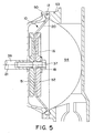
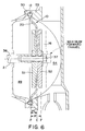
- Diaphragm 10 Shown in Figs. 2, 4, and 5-7 is a pump diaphragm 10 that is partially preloaded according to the present invention.
- Diaphragm 10 includes a outer attachment portion 12 that is clamped or otherwise attached and held stationary between pump housing sections 50 and 53 during operation of the pump as shown sequentially in Figs. 5-7.
- outer attachment portion 12 is adapted for attachment to a pump.
- outer attachment portion 12 can be formed with an enlarged bead, or a dovetailed portion as shown or may alternately be provided with a plurality of holes for receiving fastening members to retain the diaphragm in the pump housing.
- Diaphragm 10 also includes an inner attachment portion 16 having an opening 18 located at approximately the centre of the diaphragm.
- an annular working portion 20 connects the outer and inner attachment portions.
- inner attachment portion 16 is attached to a pump to define a motive fluid chamber 49 and a pumping fluid chamber 54 by clamping between a pair of clamping washers 51, 52 each having a centrally positioned opening to be aligned with diaphragm opening 18.
- the openings in clamping washers 51, 52 and inner attachment portion 16 are adapted to attach to an end of a diaphragm rod 36 or other member for moving the annular working portion 20 and the inner attachment portion 16 in a reciprocating manner, relative to the fixed outer attachment portion 12, along axis 21.
- diaphragm rod 36 is connected to clamping washers 51, 52 at diaphragm inner attachment portion 16 by a threaded bolt 37 passing therethrough as shown.
- Diaphragm rod 36 may also be either operatively connected to a mechanical driving means or may be connected to a second diaphragm.
- outer attachment portion 12 defines a first plane (P) and is disposed about an axis 21 that is substantially perpendicular to the first plane.
- Inner attachment portion 16 is disposed substantially perpendicular to axis 21 of the outer attachment portion 12 and defines a second plane (C).
- Inner attachment portion 16 is movable away from the outer attachment portion 12 into a fully extended pumping position defining a third plane (F).
- the first plane (P) and the second plane (C) are spaced at a distance to define a preload distance (PC) when the diaphragm is at rest.
- the first plane (P) and third plane (F) are spaced to define a pump stroke distance (PF) when the diaphragm is fully extended with the preload distance (PC) being from about 25 percent to about 85 percent of the pump stroke distance.
- the preload distance is from about 50 percent to about 75 percent of the pump stroke distance with most preferred loading being at 67 percent.
- annular working portion 20 is provided in a convoluted form shown in Figs. 2 and 6 comprising empirically derived radii such that when inner attachment portion 16 is moved to the fully extended position (shown in Fig. 7), the annular working portion 20 is stretched to form a linear wall.
- the radii of annular working portion 20 are provided such that, when inner attachment portion 16 is in the fully extended position, a peripheral portion 17 forms annularly between the inner attachment portion 16 and the annular working portion 20.
- the convoluted portion of annular working portion 20 is preferably spaced from outer attachment portion 12 as shown to reduce wear caused by pump housing sections 50 and 53 during operation of the pump.
- the useful life of the partially preloaded diaphragm may be further enhanced by reducing the amount of excess material to reduce the tendency of the diaphragm to buckle during mid-stroke.
- the chord length of annular working portion 20 is, preferably, the minimum that is needed to prevent overstressing at the end of the stroke.
- diaphragms having an annular working portion 20 that stretches to form peripheral portion 17, described above and shown in Figure 7, is most preferred because it achieves this reduction in diaphragm material.
- thermoplastic elastomers which may be employed include SANTOPRENE® blend of EPDM rubber and polypropylene (available from Advanced Elastomer Systems, Akron, OH), HYLENE® diisocyanate and HYTREL® polyester elastomers (available from DuPont Company, Wilmington, DE), GEOLAST® polypropylene and nitrile rubber blend (available from Advanced Elastomer Systems, Akron, OH), SARLINK® elastomer (available from DSM Elastomers, The Netherlands), and various thermoplastic urethanes including polyether and polyester based polyurethanes, such as ESTANE® thermoplastic polyurethane (available from B F Goodrich, Cleveland, OH).
- SANTOPRENE® blend of EPDM rubber and polypropylene available from Advanced Elastomer Systems, Akron, OH
- HYLENE® diisocyanate and HYTREL® polyester elastomers available from DuPont Company, Wilmington, DE
- thermoplastic elastomers A suitable listing of usable thermoplastic elastomers is given in "Elastomerics,” Oct. 1986, v. 118, no. 10. pp. 13-19. Although the polyurethanes yield superior abrasion resistance and have excellent flexing properties, SANTOPRENE® thermoplastic elastomer is preferred for many applications because of lower cost, and long flex life when employing the preferred wall design. The thermoplastic elastomers provide advantages of both thermoplastics and elastomers separately. Additionally, fluoropolymers such as TEFLON® polytetrafluoro-ethylene (available from DuPont Company, Wilmington, DE) may also be employed in the diaphragms.
- TEFLON® polytetrafluoro-ethylene available from DuPont Company, Wilmington, DE
- diaphragms of other materials with similar or greater stiffnesses may be utilised to improve their useful flexure lives.
Landscapes
- Engineering & Computer Science (AREA)
- Mechanical Engineering (AREA)
- General Engineering & Computer Science (AREA)
- Reciprocating Pumps (AREA)
Applications Claiming Priority (2)
| Application Number | Priority Date | Filing Date | Title |
|---|---|---|---|
| US27422 | 1987-03-18 | ||
| US10/027,422 US20030110939A1 (en) | 2001-12-19 | 2001-12-19 | Partially preloaded pump diaphragms |
Publications (2)
| Publication Number | Publication Date |
|---|---|
| EP1323924A2 true EP1323924A2 (de) | 2003-07-02 |
| EP1323924A3 EP1323924A3 (de) | 2003-11-26 |
Family
ID=21837647
Family Applications (1)
| Application Number | Title | Priority Date | Filing Date |
|---|---|---|---|
| EP02258415A Withdrawn EP1323924A3 (de) | 2001-12-19 | 2002-12-05 | Zum Teil vorgespannte Pumpenmembran |
Country Status (3)
| Country | Link |
|---|---|
| US (1) | US20030110939A1 (de) |
| EP (1) | EP1323924A3 (de) |
| CA (1) | CA2413376A1 (de) |
Families Citing this family (19)
| Publication number | Priority date | Publication date | Assignee | Title |
|---|---|---|---|---|
| US6901960B2 (en) * | 2002-09-06 | 2005-06-07 | Ingersoll-Rand Company | Double diaphragm pump including spool valve air motor |
| US6865981B2 (en) * | 2003-03-11 | 2005-03-15 | Ingersoll-Rand Company | Method of producing a pump |
| US6883417B2 (en) * | 2003-03-19 | 2005-04-26 | Ingersoll-Rand Company | Connecting configuration for a diaphragm in a diaphragm pump |
| CN104382691B (zh) | 2007-11-21 | 2018-08-31 | 史密夫及内修公开有限公司 | 伤口包敷物 |
| GB0723855D0 (en) | 2007-12-06 | 2008-01-16 | Smith & Nephew | Apparatus and method for wound volume measurement |
| CH702437A1 (fr) * | 2009-12-23 | 2011-06-30 | Jean-Denis Rochat | Pompe volumetrique alternative a membrane pour usage medical. |
| CH702436A1 (fr) * | 2009-12-23 | 2011-06-30 | Jean-Denis Rochat | Pompe doseuse a usage medical. |
| GB201015656D0 (en) | 2010-09-20 | 2010-10-27 | Smith & Nephew | Pressure control apparatus |
| US8596648B2 (en) | 2010-10-22 | 2013-12-03 | Oshkosh Corporation | Pump for vehicle suspension system |
| US9067003B2 (en) | 2011-05-26 | 2015-06-30 | Kalypto Medical, Inc. | Method for providing negative pressure to a negative pressure wound therapy bandage |
| US9084845B2 (en) | 2011-11-02 | 2015-07-21 | Smith & Nephew Plc | Reduced pressure therapy apparatuses and methods of using same |
| CN104507513B (zh) | 2012-03-20 | 2017-04-12 | 史密夫及内修公开有限公司 | 基于动态占空比阈值确定的减压治疗系统的控制操作 |
| US9427505B2 (en) | 2012-05-15 | 2016-08-30 | Smith & Nephew Plc | Negative pressure wound therapy apparatus |
| US9377017B2 (en) * | 2012-11-15 | 2016-06-28 | Shenzhen Mindray Bio-Medical Electronics Co., Ltd. | Extended elasticity of pump membrane with conserved pump force |
| CN205586102U (zh) * | 2014-12-01 | 2016-09-21 | 洁碧有限公司 | 防水无线口腔冲洗器 |
| US10737002B2 (en) | 2014-12-22 | 2020-08-11 | Smith & Nephew Plc | Pressure sampling systems and methods for negative pressure wound therapy |
| EP3280676B1 (de) | 2016-04-08 | 2018-11-07 | Oshkosh Corporation | Niveauregulierungssystem für ein lift-gerät |
| JP6895493B2 (ja) * | 2019-08-27 | 2021-06-30 | 株式会社タクミナ | ダイヤフラムポンプ |
| DE102020125567B4 (de) * | 2020-09-30 | 2026-04-09 | Ulman Dichtungstechnik Gmbh | Verbundmembran mit Einsatz und Öffnung umgebende Verdickung für Membranpumpen |
Citations (1)
| Publication number | Priority date | Publication date | Assignee | Title |
|---|---|---|---|---|
| US3011758A (en) | 1958-05-01 | 1961-12-05 | Hills Mccanna Co | Valve diaphragms |
Family Cites Families (4)
| Publication number | Priority date | Publication date | Assignee | Title |
|---|---|---|---|---|
| DE3813500A1 (de) * | 1988-04-22 | 1989-11-02 | Alkor Gmbh | Membranpumpe oder membrankompressor |
| DE9306501U1 (de) * | 1993-04-29 | 1993-09-02 | ASF, Gesellschaft für elektrotechnische Geräte mbH, 82178 Puchheim | Membrane für eine Membranpumpe zum Fördern eines brennbaren Fluids |
| DE9403103U1 (de) * | 1994-02-24 | 1994-04-14 | ASF, Gesellschaft für elektrotechnische Geräte mbH, 82178 Puchheim | Membrane für eine Membranpumpe zum Fördern eines brennbaren Fluids |
| US5996470A (en) * | 1997-11-18 | 1999-12-07 | Westinghouse Air Brake Company | Wear ring for diaphragm and outer piston |
-
2001
- 2001-12-19 US US10/027,422 patent/US20030110939A1/en not_active Abandoned
-
2002
- 2002-11-29 CA CA002413376A patent/CA2413376A1/en not_active Abandoned
- 2002-12-05 EP EP02258415A patent/EP1323924A3/de not_active Withdrawn
Patent Citations (1)
| Publication number | Priority date | Publication date | Assignee | Title |
|---|---|---|---|---|
| US3011758A (en) | 1958-05-01 | 1961-12-05 | Hills Mccanna Co | Valve diaphragms |
Also Published As
| Publication number | Publication date |
|---|---|
| US20030110939A1 (en) | 2003-06-19 |
| CA2413376A1 (en) | 2003-06-19 |
| EP1323924A3 (de) | 2003-11-26 |
Similar Documents
| Publication | Publication Date | Title |
|---|---|---|
| US20030110939A1 (en) | Partially preloaded pump diaphragms | |
| US6145430A (en) | Selectively bonded pump diaphragm | |
| US4864918A (en) | Thermoplastic diaphragm | |
| US5349896A (en) | Pump diaphragm | |
| US5894784A (en) | Backup washers for diaphragms and diaphragm pump incorporating same | |
| EP1230469B1 (de) | Mehrschichtige Membranpumpe | |
| US5743170A (en) | Diaphragm mechanism for an air driven diaphragm pump | |
| US10273953B2 (en) | Methods of manufacturing a pneumatic reciprocating fluid pump with improved check valve assembly | |
| EP1847711B1 (de) | Peristaltische Pumpe, Verfahren zur Herstellung eines Schlauchs dafür und Schlauch für eine solche Pumpe | |
| AU638605B2 (en) | Annular support for a seal for a tilt piston | |
| GB2452047A (en) | Diaphragm for use in a fluid pump comprising a disc of resilient material whose curvature is formed from a plurality of steps | |
| US7424847B2 (en) | Diaphragm assembly for a pump | |
| CA2251222C (en) | Extended wear pump diaphragm | |
| US5996470A (en) | Wear ring for diaphragm and outer piston | |
| CA2220363C (en) | Abrasion resistant diaphragm | |
| CA2241250C (en) | Ribbed diaphragm | |
| EP3483439B1 (de) | Abrieb- und durchstichfeste membran | |
| EP1044330B1 (de) | Ventilaufbau für hochdruckpumpen | |
| US11754181B2 (en) | Overmolded diaphragm for use in a pump | |
| US20240035569A1 (en) | Volume control actuator including non-contact cylinder | |
| MXPA98009670A (en) | Wear ring for diaphragm and piston exte | |
| MXPA98004499A (en) | Abrasive resistance diaphragm | |
| CA2233772A1 (en) | Diaphragm seal |
Legal Events
| Date | Code | Title | Description |
|---|---|---|---|
| PUAI | Public reference made under article 153(3) epc to a published international application that has entered the european phase |
Free format text: ORIGINAL CODE: 0009012 |
|
| AK | Designated contracting states |
Designated state(s): AT BE BG CH CY CZ DE DK EE ES FI FR GB GR IE IT LI LU MC NL PT SE SI SK TR |
|
| AX | Request for extension of the european patent |
Extension state: AL LT LV MK RO |
|
| PUAL | Search report despatched |
Free format text: ORIGINAL CODE: 0009013 |
|
| AK | Designated contracting states |
Kind code of ref document: A3 Designated state(s): AT BE BG CH CY CZ DE DK EE ES FI FR GB GR IE IT LI LU MC NL PT SE SI SK TR |
|
| AX | Request for extension of the european patent |
Extension state: AL LT LV MK RO |
|
| AKX | Designation fees paid | ||
| REG | Reference to a national code |
Ref country code: DE Ref legal event code: 8566 |
|
| STAA | Information on the status of an ep patent application or granted ep patent |
Free format text: STATUS: THE APPLICATION IS DEEMED TO BE WITHDRAWN |
|
| 18D | Application deemed to be withdrawn |
Effective date: 20040527 |