EP1324003A2 - Lenkwinkelsensor - Google Patents
Lenkwinkelsensor Download PDFInfo
- Publication number
- EP1324003A2 EP1324003A2 EP02023078A EP02023078A EP1324003A2 EP 1324003 A2 EP1324003 A2 EP 1324003A2 EP 02023078 A EP02023078 A EP 02023078A EP 02023078 A EP02023078 A EP 02023078A EP 1324003 A2 EP1324003 A2 EP 1324003A2
- Authority
- EP
- European Patent Office
- Prior art keywords
- light
- sensor
- sections
- sensor according
- light guide
- Prior art date
- Legal status (The legal status is an assumption and is not a legal conclusion. Google has not performed a legal analysis and makes no representation as to the accuracy of the status listed.)
- Granted
Links
Images


Classifications
-
- B—PERFORMING OPERATIONS; TRANSPORTING
- B62—LAND VEHICLES FOR TRAVELLING OTHERWISE THAN ON RAILS
- B62D—MOTOR VEHICLES; TRAILERS
- B62D15/00—Steering not otherwise provided for
- B62D15/02—Steering position indicators ; Steering position determination; Steering aids
-
- G—PHYSICS
- G01—MEASURING; TESTING
- G01D—MEASURING NOT SPECIALLY ADAPTED FOR A SPECIFIC VARIABLE; ARRANGEMENTS FOR MEASURING TWO OR MORE VARIABLES NOT COVERED IN A SINGLE OTHER SUBCLASS; TARIFF METERING APPARATUS; MEASURING OR TESTING NOT OTHERWISE PROVIDED FOR
- G01D5/00—Mechanical means for transferring the output of a sensing member; Means for converting the output of a sensing member to another variable where the form or nature of the sensing member does not constrain the means for converting; Transducers not specially adapted for a specific variable
- G01D5/26—Mechanical means for transferring the output of a sensing member; Means for converting the output of a sensing member to another variable where the form or nature of the sensing member does not constrain the means for converting; Transducers not specially adapted for a specific variable characterised by optical transfer means, i.e. using infrared, visible, or ultraviolet light
- G01D5/32—Mechanical means for transferring the output of a sensing member; Means for converting the output of a sensing member to another variable where the form or nature of the sensing member does not constrain the means for converting; Transducers not specially adapted for a specific variable characterised by optical transfer means, i.e. using infrared, visible, or ultraviolet light with attenuation or whole or partial obturation of beams of light
- G01D5/34—Mechanical means for transferring the output of a sensing member; Means for converting the output of a sensing member to another variable where the form or nature of the sensing member does not constrain the means for converting; Transducers not specially adapted for a specific variable characterised by optical transfer means, i.e. using infrared, visible, or ultraviolet light with attenuation or whole or partial obturation of beams of light the beams of light being detected by photocells
- G01D5/347—Mechanical means for transferring the output of a sensing member; Means for converting the output of a sensing member to another variable where the form or nature of the sensing member does not constrain the means for converting; Transducers not specially adapted for a specific variable characterised by optical transfer means, i.e. using infrared, visible, or ultraviolet light with attenuation or whole or partial obturation of beams of light the beams of light being detected by photocells using displacement encoding scales
- G01D5/34707—Scales; Discs, e.g. fixation, fabrication, compensation
- G01D5/34715—Scale reading or illumination devices
- G01D5/34723—Scale reading or illumination devices involving light-guides
Definitions
- the invention relates to a steering angle sensor for Determining the rotational position of a steering wheel Vehicle, with one with the steering wheel directly or indirectly connected, carrying an optically scannable coding Code disc, with at least one optical beam emitting transmission element and preferably several Beam receiving elements, and with a Light guide for deflecting and, if necessary, fanning out the beams emitted by the transmitting element, the Light guide at least one light coupling section and preferably has a plurality of light coupling sections.
- Such a steering angle sensor is from DE 199 60 789 A1 became known.
- Steering angle sensors has been found to be disadvantageous that light entering the steering angle sensor from the Receiving elements is received and the measurement result of the Steering angle sensor adversely affected.
- the present invention is therefore based on the object based on a known steering angle sensor such to further develop that penetrating into the steering angle sensor Scattered light does not adversely affect the measurement result.
- This task is the beginning of a steering angle sensor described type according to the invention solved in that between the transmitting element and the Light coupling section and / or between the Light decoupling sections and the receiver elements Aperture element is arranged, the Light coupling section and / or the receiver elements protects against stray light.
- This has the advantage that in the Steering angle sensor penetrating light the measurement result of the Steering angle sensor not adulterated or negative affected.
- the aperture element points in the area of the transmission element and / or a breakthrough in the area of the receiver elements or breakthroughs, especially in the form of slots or Circular cylinders, on.
- a breakthrough in the area of the receiver elements or breakthroughs especially in the form of slots or Circular cylinders, on.
- the breakthroughs limit the Cross sections of the respective radiation channels.
- the diaphragm element advantageously has an in Appropriate thickness directed in the direction of the radiation channels that is 2 to 8 times thicker than the thickness of the Code disk
- the aperture element is preferably made of a light absorbing material, so that in the area of Breakthroughs light, and especially stray light, do not turn on the surfaces of the breakthroughs are reflected and above such a reflection to the receiver elements arrives.
- the transmitter element, the receiver elements and the aperture element is arranged on a sensor board. This has the advantage that a positionally accurate Arranging the respective elements is achieved.
- the invention is particularly advantageous if that Aperture element the beam path between the transmission element and completely shields the light coupling portion. This prevents rays that are not from the transmission element are transmitted via the Light coupling section get into the light guide can.
- the diaphragm element the beam path or the beam paths between the Shields the code disk and the receiver elements, the Code disc between the panel element and the Light coupling sections existing gap largely fills. This ensures that no stray light over the area between the light extraction sections and the receiver elements reach the receiver elements can.
- the light guide over fastening sections and / or positioning sections directly with the sensor housing coupled.
- This has the advantage of positioning of the light guide directly opposite the sensor housing is achieved.
- the mounting sections that be designed, for example, as fastening tabs can, the light guide can be attached to the housing become.
- positioning sections for example Positioning pins that go into associated positioning recesses intervene, provided.
- the light guide is preferably arranged such that it rests directly on the sensor board. This has the Advantage that an exact position of the Optical fiber with respect to the sensor board and that on the Sensor board arranged transmitter or receiver elements given is.
- the light guide advantageously has at least one Positioning section that passes through the sensor board and in one provided on the sensor housing Positioning recess engages or passes through.
- a positioning section the can be designed, for example, as a positioning pin, is achieved on the one hand that the sensor board with respect the light guide is positioned and on the other hand that also the light guide together with the sensor board compared to the Sensor housing can be arranged precisely.
- a preferred embodiment results when the Aperture element at least in sections between the Light guide and the sensor board is arranged. Thereby can in particular be guaranteed that the Beam path between the transmitting element and the Light coupling section of the light guide through the Panel element fully protected or shielded can be. This can also be done via the light guide Panel element arranged on the sensor board or be attached.
- the diaphragm element is advantageously directly with coupled to the sensor board. This will create a exact position of the panel element on the Sensor board guaranteed.
- the sensor board advantageously has Positioning recesses or positioning sections on the for receiving provided on the panel element Positioning sections or positioning recesses are provided.
- Positioning sections or Positioning recesses can, for example, as Positioning pins or positioning holes may be formed.
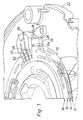
- FIG. 1 shows sections and in perspective Representation of a section of a code disk 10, which a total of four code tracks 12, 14, 16 and 18 breakthroughs 20 has as coding.
- the code disc 10 is with a Steering column not shown, so that they the Steering wheel rotation follows.
- On the inside of the The lower part of a housing 22 is a printed circuit board 24 arranged, on which in the radial distance of the Code tracks 12 to 18 receiver, not shown are arranged and on which also a panel element 25 and an optical fiber 26 is arranged. From the light guide 26 and is hidden by the panel element 25 also a transmission element in the form of an infrared light-emitting diode 28 on the circuit board 24.
- FIG. 2 shows a view of the top of the light guide 26, and there are clearly the mounting holes 30 to recognize via which the light guide 26 on the housing 22 is fixed.
- the prism 34 has three reflective surfaces 36, 38 and 40 which are preferred are mirrored. That of the infrared light-emitting diode 28 radiated light strikes a light coupling section 42.
- This light coupling section 42 is convex designed and in one piece at the bottom of the Light guide 26 integrally formed.
- the Light coupling section 42 immediately below the Prism 34.
- the bottom 54 of the fingers 48 to 52 is the top facing the code disc 10 and has two decoupling sections 56 and 58. These coupling sections 56 and 58 are convexly curved, the coupling-out section 58 set back slightly behind the coupling-out section 56 is so that it is at a greater distance from the code disk 10 having.
- the top 60 of the fingers 48 to 52 has a total of four Reflective surfaces 62, 64, 66 and 68 on that in radial Direction are arranged one behind the other.
- the Reflective surfaces form an angle different from 90 ° to the level of the code disc 10.
- These reflection surfaces too 62 to 68 and the reflection surfaces 44 and 46 are mirrored.
- the reflection surfaces 62 to 68 have the Purpose that part of what is in the fingers 48 to 52 Light towards the coupling sections 56 and 58, i.e. is deflected towards the code disc 10. Thereby are in the two coupling sections 56 and 58, respectively two light coupling sections 70, 72 and 74, 76 are formed.
- the position of these light extraction sections 70 to 76 corresponds exactly to the radial positions of the code tracks 12 until 18
- circuit board 24 is the circuit board 24, the panel element 25 and the light guide 26 as individual parts in Exposure representation shown.
- twelve receiver elements 78 can be clearly seen, whereby three receiver elements each one of the code tracks Scan 12, 14, 16 and 18.
- the receiver elements 78 are advantageously designed as photo sensors.
- On the Printed circuit board 24 is also clearly visible Transmitting element in the form of an IR light-emitting diode 28. Die Light emitting diode 28 and the receiver elements 78 are advantageously carried out in chip-on-board technology. This has the advantage of very low position tolerances between the individual elements 78 and 28 are possible.
- the circuit board 24 has a total of four Positioning recesses 80, 82, 84 and 86 on.
- the Positioning recesses 80 and 82 are for receiving from the side of the circuit board 24 facing the Diaphragm element 25 arranged positioning sections 88 and 90 are provided.
- the one circular cross section having positioning section 88 is mounted in the Condition of a corresponding cross section having positioning recess 80 added. Accordingly, the positioning section 90 of the Positioning recess 80 added. This will achieved that the panel element 25 is positioned exactly on the Printed circuit board 24 or exactly in relation to the Receiver elements 78 and the transmitting element 28 arranged becomes.
- the aperture element 25 has in the area of Receiver elements 78 each have a slot-shaped Breakthrough 92 on. So there are a total of twelve Breakthroughs 92 are present, which are those of the Light decoupling sections 70, 72, 74, 76 of the fingers 48, Shield 50 and 52 emerging beam paths.
- the panel element 25 in the area of Transmitting element 28 has an opening 94, the one circular cross section. Breakthrough 94 can the rays emitted by the transmitting element 28 undisturbed in the light coupling section 42 of the Light guide 26 arrive.
- the aperture element 25 has a certain thickness d that Is 3 to 5 times thicker than the code disk 10, and is off a light absorbing material. This will prevents that in particular in the openings 92 obliquely incident stray light to the receiver elements 78 can penetrate.
- the positioning recesses 84 and 86 of the printed circuit board 24 are for receiving positioning pins 96 and 98 of the Light guide 26 provided. This will become the light guide exactly in relation to the printed circuit board 24 and thus exactly in position to the transmitter element 28 and the receiver elements 78 arranged.
- the Positioning sections or positioning pins 88 and 90 are here in the associated positioning recesses or bores 80 and 82 arranged.
- the positioning pin 98 which is longer than that Positioning pin 96 is formed, passes through the Recess 86 of the circuit board 24 and engages in one Recess 102 on the lower housing part 22 Positional arrangement of the light guide 26 together Aperture element 25 and circuit board 24 compared to the Lower housing part 22, or relative to the entire Sensor housing, possible.
- the individual components 26, 25, 24 and 22 are consequently in position with respect to one another aligned, whereby small position tolerances can be achieved are.
- the positioning of the light guide 26, the Aperture element 25 and the circuit board 24 relative to the Housing 22 is of particular importance since the storage the code disk 10 also opposite the housing 22 he follows.
- the light guide 26, and thus the diaphragm element 25 and Printed circuit board 24 can via the mounting holes 30th of the light guide 26 by means of known screws on the Lower housing part 22 are attached.
- Fig. 1 can also be seen that the Aperture element 25 the beam path or the beam paths between the code disk 10 and the receiver elements 78 shields, the code disc 10 a between the Aperture element 25 and the light decoupling sections 70, 72, 74 and 76 existing gap 104 largely fills. As a result, no light can advantageously between the Light extraction sections 70, 72, 74, 76 and the Aperture element 25 get into the openings 92 and that Adversely affect the measurement result of the sensor.
Landscapes
- Engineering & Computer Science (AREA)
- Physics & Mathematics (AREA)
- General Physics & Mathematics (AREA)
- Chemical & Material Sciences (AREA)
- Combustion & Propulsion (AREA)
- Transportation (AREA)
- Mechanical Engineering (AREA)
- Optical Transform (AREA)
Abstract
Description
- Fig. 1:
- eine perspektivische Darstellung eines Abschnitts einer offenen, erfindungsgemäßen Sensoreinheit;
- Figur 2 und 3:
- eine perspektivische Draufsicht und eine perspektivische Unteransicht eines Lichtleiters;
- Figur 4
- einen Lichtleiter, ein Blendenelement und eine Sensorplatine in Einzelteildarstellung;
- Figur 5
- das auf der Sensorplatine angeordnete Blendenelement; und
- Figur 6
- einen Schnitt durch das auf der Sensorplatine angeordnete Blendenelement.
Claims (12)
- Lenkwinkelsensor zur Bestimmung der Drehstellung eines Lenkrades eines Fahrzeuges, mit einer mit dem Lenkrad direkt oder indirekt verbundenen, eine optisch abtastbare Codierung (12) tragenden Codescheibe (10), mit wenigstens einem optische Strahlen aussendenden Sendeelement (28) und vorzugsweise mehreren die Strahlen empfangenden Empfängerelementen (78), und mit einem Lichtleiter (26) zum Umlenken der von dem Sendeelement (28) abgestrahlten Strahlen, wobei der Lichtleiter (26) wenigstens einen Lichteinkopplungsabschnitt (42) und vorzugsweise mehrere Lichtauskopplungsabschnitte (70, 72, 74, 76) aufweist, dadurch gekennzeichnet, dass zwischen dem Sendeelement (28) und dem Lichteinkopplungsabschnitt (42) und/oder zwischen den Lichtauskopplungsabschnitten (70, 72, 74, 76) und den Empfängerelementen (78) ein Blendenelement (25) angeordnet ist, das den Lichteinkopplungsabschnitt (42) und/oder die Empfängerelemente (78) vor Streulicht schützt.
- Sensor nach Anspruch 1, dadurch gekennzeichnet, dass das Blendenelement (25) im Bereich des Sendeelements (28) und/oder im Bereich der Empfängerelemente (78) einen Durchbruch bzw. Durchbrüche (92, 94), insbesondere in Form von Schlitzen oder Kreiszylindern, aufweist.
- Sensor nach Anspruch 1 oder 2, dadurch gekennzeichnet, dass das Blendenelement (25) eine Dicke (d) aufweist, die 2- bis 8-mal und vorzugsweise 3- bis 5-mal dicker ist als die Dicke der Codescheibe (20).
- Sensor nach Anspruch 1, 2 oder 3, dadurch gekennzeichnet, dass das Sendeelement (28), die Empfängerelemente (78) und das Blendenelement (25) auf einer Sensorplatine (24) angeordnet sind.
- Sensor nach einem der vorhergehenden Ansprüche, dadurch gekennzeichnet, dass das Blendenelement (25) den Strahlengang zwischen dem Sendelement (28) und dem Lichteinkopplungsabschnitt (42) vollständig abschirmt.
- Sensor nach einem der vorhergehenden Ansprüche, dadurch gekennzeichnet, dass das Blendenelement (25) den Strahlengang bzw. die Strahlengänge zwischen der Codescheibe (10) und den Empfängerelementen (78) abschirmt, wobei die Codescheibe (10) einen zwischen dem Blendenelement (25) und den Lichtauskopplungsabschnitten (70, 72, 74, 76) vorhandenen Spalt weitgehend ausfüllt.
- Sensor nach einem der vorhergehenden Ansprüche, dadurch gekennzeichnet, dass der Lichtleiter (26) über Befestigungsabschnitte (30) und/oder Positionierabschnitte (98) direkt mit dem Sensorgehäuse (22) gekoppelt ist.
- Sensor nach Anspruch 7, dadurch gekennzeichnet, dass der Lichtleiter (26) direkt auf der Sensorplatine (24) aufliegt.
- Sensor nach Anspruch 7 oder 8, dadurch gekennzeichnet, dass der Lichtleiter (26) wenigstens einen Positionierabschnitt (98) aufweist, der die Sensorplatine (24) durchgreift und in eine am Sensorgehäuse (22) vorgesehene Positionieraussparung (102) eingreift oder diese durchgreift.
- Sensor nach einem der vorhergehenden Ansprüche, dadurch gekennzeichnet, dass das Blendenelement (25) wenigstens abschnittsweise zwischen dem Lichtleiter (26) und der Sensorplatine (24) angeordnet ist.
- Sensor nach einem der vorhergehenden Ansprüche, dadurch gekennzeichnet, dass das Blendenelement (25) direkt mit der Sensorplatine (24) gekoppelt ist.
- Sensor nach Anspruch 11, dadurch gekennzeichnet, dass die Sensorplatine (24) Positionieraussparungen (80, 82) bzw. Positionierabschnitte aufweist, die zur Aufnahme von an dem Blendenelement (25) vorgesehenen Positionierabschnitten (88, 90) bzw. Positionieraussparungen vorgesehen sind.
Applications Claiming Priority (2)
| Application Number | Priority Date | Filing Date | Title |
|---|---|---|---|
| DE10164388 | 2001-12-28 | ||
| DE2001164388 DE10164388C1 (de) | 2001-12-28 | 2001-12-28 | Lenkwinkelsensor |
Publications (3)
| Publication Number | Publication Date |
|---|---|
| EP1324003A2 true EP1324003A2 (de) | 2003-07-02 |
| EP1324003A3 EP1324003A3 (de) | 2003-08-06 |
| EP1324003B1 EP1324003B1 (de) | 2007-03-28 |
Family
ID=7711092
Family Applications (1)
| Application Number | Title | Priority Date | Filing Date |
|---|---|---|---|
| EP02023078A Expired - Lifetime EP1324003B1 (de) | 2001-12-28 | 2002-10-17 | Lenkwinkelsensor |
Country Status (2)
| Country | Link |
|---|---|
| EP (1) | EP1324003B1 (de) |
| DE (2) | DE10164388C1 (de) |
Cited By (2)
| Publication number | Priority date | Publication date | Assignee | Title |
|---|---|---|---|---|
| EP1533212A1 (de) * | 2003-11-20 | 2005-05-25 | Valeo Schalter und Sensoren GmbH | Lenkwinkelsensor |
| DE102012105963A1 (de) * | 2012-07-04 | 2014-05-08 | Hella Kgaa Hueck & Co. | Drehwinkelsensor |
Families Citing this family (4)
| Publication number | Priority date | Publication date | Assignee | Title |
|---|---|---|---|---|
| DE102007052978A1 (de) * | 2007-11-07 | 2009-05-14 | Valeo Schalter Und Sensoren Gmbh | Anordnung zur Erfassung eines Drehwinkels |
| DE102008004047B4 (de) * | 2008-01-11 | 2022-08-18 | Kostal Automobil Elektrik Gmbh & Co. Kg | Absolut messender optischer Drehwinkelsensor |
| CN102269572A (zh) * | 2011-04-26 | 2011-12-07 | 中国科学院上海光学精密机械研究所 | 光盘翘曲测试装置和测试方法 |
| CN112965253A (zh) * | 2021-03-24 | 2021-06-15 | Oppo广东移动通信有限公司 | 光学系统和穿戴式增强现实显示设备 |
Family Cites Families (5)
| Publication number | Priority date | Publication date | Assignee | Title |
|---|---|---|---|---|
| WO1995033180A1 (en) * | 1994-06-01 | 1995-12-07 | Stridsberg Innovation Ab | Position transducer |
| DE19754191A1 (de) * | 1997-12-06 | 1999-06-10 | Itt Mfg Enterprises Inc | Modulare Anordnung eines Lenkwinkelsensors |
| DE29805392U1 (de) * | 1998-03-25 | 1999-08-05 | Dr. Johannes Heidenhain Gmbh, 83301 Traunreut | Optoelektronische Baugruppe |
| DE29915998U1 (de) * | 1999-09-13 | 2000-02-03 | Leopold Kostal GmbH & Co KG, 58507 Lüdenscheid | Optoelektronischer Lenkwinkelsensor |
| DE19960789A1 (de) * | 1999-12-15 | 2001-06-28 | Valeo Schalter & Sensoren Gmbh | Lenkwinkelsensor |
-
2001
- 2001-12-28 DE DE2001164388 patent/DE10164388C1/de not_active Revoked
-
2002
- 2002-10-17 EP EP02023078A patent/EP1324003B1/de not_active Expired - Lifetime
- 2002-10-17 DE DE50209825T patent/DE50209825D1/de not_active Expired - Lifetime
Cited By (3)
| Publication number | Priority date | Publication date | Assignee | Title |
|---|---|---|---|---|
| EP1533212A1 (de) * | 2003-11-20 | 2005-05-25 | Valeo Schalter und Sensoren GmbH | Lenkwinkelsensor |
| DE102012105963A1 (de) * | 2012-07-04 | 2014-05-08 | Hella Kgaa Hueck & Co. | Drehwinkelsensor |
| US9945694B2 (en) | 2012-07-04 | 2018-04-17 | Hella Kgaa Hueck & Co. | Rotary angle sensor |
Also Published As
| Publication number | Publication date |
|---|---|
| DE50209825D1 (de) | 2007-05-10 |
| DE10164388C1 (de) | 2003-04-30 |
| EP1324003B1 (de) | 2007-03-28 |
| EP1324003A3 (de) | 2003-08-06 |
Similar Documents
| Publication | Publication Date | Title |
|---|---|---|
| EP0843180B1 (de) | Laserabstandsermittlungsvorrichtung | |
| DE69207179T2 (de) | Optoelektronisches bauteil | |
| DE3803529C2 (de) | ||
| EP1933172B1 (de) | Lichtschrankenanordnung | |
| EP3388857A1 (de) | Laserscanner und verfahren zur überprüfung der funktionsfähigkeit | |
| EP2157449B1 (de) | Lichtgitter | |
| DE10164388C1 (de) | Lenkwinkelsensor | |
| EP2053428B1 (de) | Optoelektronischer Sensor | |
| DE19808004A1 (de) | Bauteil zur optischen Datenübertragung | |
| EP1108976B1 (de) | Lenkwinkelsensor | |
| EP1514750B1 (de) | Kombinierte Sensoranordnung zur Detektion von Umgebungslicht und Regen | |
| DE102024112051A1 (de) | Beleuchtungsvorrichtung für Fahrzeuge | |
| DE20122605U1 (de) | Lenkwinkelsensor | |
| EP3324218B1 (de) | Mehrstrahllichtschranke | |
| DE20122604U1 (de) | Lenkwinkelsensor | |
| EP0990579A2 (de) | Fahrzeugleuchte | |
| DE102019124265B4 (de) | Optoelektronischer Sensor und Verfahren zum Erfassen von Objekten in einem Überwachungsbereich | |
| EP2101197A1 (de) | Gabellichtschranke | |
| DE102022116100A1 (de) | Sensor | |
| DE10205294B4 (de) | Optoelektronische Vorrichtung | |
| EP1341118B1 (de) | Optoelektronische Vorrichtung | |
| DE19844238C2 (de) | Optoelektronische Vorrichtung | |
| DE102005045280B3 (de) | Distanzsensor | |
| EP1245475B1 (de) | Lenkwinkelsensor | |
| DE102006048298B3 (de) | Lichttaster mit Hintergrundausblendung zum Detektieren von Objekten in einem vorgegebenen Abstandsbereich |
Legal Events
| Date | Code | Title | Description |
|---|---|---|---|
| PUAI | Public reference made under article 153(3) epc to a published international application that has entered the european phase |
Free format text: ORIGINAL CODE: 0009012 |
|
| PUAL | Search report despatched |
Free format text: ORIGINAL CODE: 0009013 |
|
| AK | Designated contracting states |
Designated state(s): AT BE BG CH CY CZ DE DK EE ES FI FR GB GR IE IT LI LU MC NL PT SE SK TR |
|
| AX | Request for extension of the european patent |
Extension state: AL LT LV MK RO SI |
|
| AK | Designated contracting states |
Designated state(s): AT BE BG CH CY CZ DE DK EE ES FI FR GB GR IE IT LI LU MC NL PT SE SK TR |
|
| AX | Request for extension of the european patent |
Extension state: AL LT LV MK RO SI |
|
| RIC1 | Information provided on ipc code assigned before grant |
Ipc: 7B 62D 15/02 B Ipc: 7G 01D 5/347 B Ipc: 7G 01D 5/36 B Ipc: 7G 01B 7/30 A |
|
| 17P | Request for examination filed |
Effective date: 20030910 |
|
| AKX | Designation fees paid |
Designated state(s): DE ES FR GB IT |
|
| 17Q | First examination report despatched |
Effective date: 20040622 |
|
| GRAP | Despatch of communication of intention to grant a patent |
Free format text: ORIGINAL CODE: EPIDOSNIGR1 |
|
| GRAS | Grant fee paid |
Free format text: ORIGINAL CODE: EPIDOSNIGR3 |
|
| GRAA | (expected) grant |
Free format text: ORIGINAL CODE: 0009210 |
|
| AK | Designated contracting states |
Kind code of ref document: B1 Designated state(s): DE ES FR GB IT |
|
| REG | Reference to a national code |
Ref country code: GB Ref legal event code: FG4D Free format text: NOT ENGLISH |
|
| REF | Corresponds to: |
Ref document number: 50209825 Country of ref document: DE Date of ref document: 20070510 Kind code of ref document: P |
|
| PG25 | Lapsed in a contracting state [announced via postgrant information from national office to epo] |
Ref country code: ES Free format text: LAPSE BECAUSE OF FAILURE TO SUBMIT A TRANSLATION OF THE DESCRIPTION OR TO PAY THE FEE WITHIN THE PRESCRIBED TIME-LIMIT Effective date: 20070709 |
|
| GBV | Gb: ep patent (uk) treated as always having been void in accordance with gb section 77(7)/1977 [no translation filed] |
Effective date: 20070328 |
|
| EN | Fr: translation not filed | ||
| PLBE | No opposition filed within time limit |
Free format text: ORIGINAL CODE: 0009261 |
|
| STAA | Information on the status of an ep patent application or granted ep patent |
Free format text: STATUS: NO OPPOSITION FILED WITHIN TIME LIMIT |
|
| 26N | No opposition filed |
Effective date: 20080102 |
|
| PG25 | Lapsed in a contracting state [announced via postgrant information from national office to epo] |
Ref country code: FR Free format text: LAPSE BECAUSE OF FAILURE TO SUBMIT A TRANSLATION OF THE DESCRIPTION OR TO PAY THE FEE WITHIN THE PRESCRIBED TIME-LIMIT Effective date: 20071116 Ref country code: GB Free format text: LAPSE BECAUSE OF FAILURE TO SUBMIT A TRANSLATION OF THE DESCRIPTION OR TO PAY THE FEE WITHIN THE PRESCRIBED TIME-LIMIT Effective date: 20070328 Ref country code: IT Free format text: LAPSE BECAUSE OF FAILURE TO SUBMIT A TRANSLATION OF THE DESCRIPTION OR TO PAY THE FEE WITHIN THE PRESCRIBED TIME-LIMIT Effective date: 20070328 |
|
| PG25 | Lapsed in a contracting state [announced via postgrant information from national office to epo] |
Ref country code: FR Free format text: LAPSE BECAUSE OF FAILURE TO SUBMIT A TRANSLATION OF THE DESCRIPTION OR TO PAY THE FEE WITHIN THE PRESCRIBED TIME-LIMIT Effective date: 20070328 |
|
| PGFP | Annual fee paid to national office [announced via postgrant information from national office to epo] |
Ref country code: DE Payment date: 20211008 Year of fee payment: 20 |
|
| REG | Reference to a national code |
Ref country code: DE Ref legal event code: R071 Ref document number: 50209825 Country of ref document: DE |