EP1324011A2 - Vorrichtung zum Feststellen des Fliessens einer Flüssigkeit - Google Patents
Vorrichtung zum Feststellen des Fliessens einer Flüssigkeit Download PDFInfo
- Publication number
- EP1324011A2 EP1324011A2 EP02445149A EP02445149A EP1324011A2 EP 1324011 A2 EP1324011 A2 EP 1324011A2 EP 02445149 A EP02445149 A EP 02445149A EP 02445149 A EP02445149 A EP 02445149A EP 1324011 A2 EP1324011 A2 EP 1324011A2
- Authority
- EP
- European Patent Office
- Prior art keywords
- flow
- detecting
- monitoring device
- pump
- cage
- Prior art date
- Legal status (The legal status is an assumption and is not a legal conclusion. Google has not performed a legal analysis and makes no representation as to the accuracy of the status listed.)
- Withdrawn
Links
Images


Classifications
-
- G—PHYSICS
- G01—MEASURING; TESTING
- G01P—MEASURING LINEAR OR ANGULAR SPEED, ACCELERATION, DECELERATION, OR SHOCK; INDICATING PRESENCE, ABSENCE, OR DIRECTION, OF MOVEMENT
- G01P13/00—Indicating or recording presence, absence, or direction, of movement
- G01P13/0006—Indicating or recording presence, absence, or direction, of movement of fluids or of granulous or powder-like substances
- G01P13/0013—Indicating or recording presence, absence, or direction, of movement of fluids or of granulous or powder-like substances by using a solid body which is shifted by the action of the fluid
- G01P13/002—Indicating or recording presence, absence, or direction, of movement of fluids or of granulous or powder-like substances by using a solid body which is shifted by the action of the fluid with electrical coupling to the indicating devices
-
- F—MECHANICAL ENGINEERING; LIGHTING; HEATING; WEAPONS; BLASTING
- F04—POSITIVE - DISPLACEMENT MACHINES FOR LIQUIDS; PUMPS FOR LIQUIDS OR ELASTIC FLUIDS
- F04D—NON-POSITIVE-DISPLACEMENT PUMPS
- F04D15/00—Control, e.g. regulation, of pumps, pumping installations or systems
- F04D15/02—Stopping of pumps, or operating valves, on occurrence of unwanted conditions
- F04D15/0209—Stopping of pumps, or operating valves, on occurrence of unwanted conditions responsive to a condition of the working fluid
- F04D15/0218—Stopping of pumps, or operating valves, on occurrence of unwanted conditions responsive to a condition of the working fluid the condition being a liquid level or a lack of liquid supply
- F04D15/0227—Lack of liquid level being detected using a flow transducer
-
- G—PHYSICS
- G01—MEASURING; TESTING
- G01F—MEASURING VOLUME, VOLUME FLOW, MASS FLOW OR LIQUID LEVEL; METERING BY VOLUME
- G01F1/00—Measuring the volume flow or mass flow of fluid or fluent solid material wherein the fluid passes through a meter in a continuous flow
- G01F1/05—Measuring the volume flow or mass flow of fluid or fluent solid material wherein the fluid passes through a meter in a continuous flow by using mechanical effects
- G01F1/20—Measuring the volume flow or mass flow of fluid or fluent solid material wherein the fluid passes through a meter in a continuous flow by using mechanical effects by detection of dynamic effects of the flow
- G01F1/28—Measuring the volume flow or mass flow of fluid or fluent solid material wherein the fluid passes through a meter in a continuous flow by using mechanical effects by detection of dynamic effects of the flow by drag-force, e.g. vane type or impact flowmeter
Definitions
- the invention concerns a device for monitoring the fluid flow in a pump outlet and in dependence thereof, controlling the current supply of an electrically driven pump motor.
- the invention is especially adapted to be used in connection with so-called submersible pumps, where an electric motor, a hydraulic unit and an intermediate seal device as a compact unit are submersed in the pumped medium, water, and where the latter is used for cooling of the electric motor.
- Pumps of this type are commonly used at construction sites, in mines etc and they very often operate during long periods without any supervision. If the pump, for some reason should cease to pump water, because of lack of water, because of the pump inlet being clogged etc, the pump outlet will contain air instead of water. As air has considerably worse cooling abilities as compared to water, there is a risk that the electric motor could be damaged. It is also a waste of energy to let the pump operate dry and in addition the parts in the hydraulic unit might be warn out because of the fact that the water contains abrasive particles that circulate within the pump housing.
- This invention solves the problem to detect air in the outlet from a pump in a simple and secure way and to disconnect the current supply of the pump in dependence of said information.
- the invention is characterized by the enclosed claims.
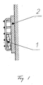
- Fig 1 shows a detection device
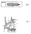
- Fig 2 a tongue element
- Fig 4 a part of a submersible pump unit and 4 an electric diagram.
- a detecting device formed like a body 1 made of a permanent magnetic material and having a higher density than the pumped medium is arranged within a cage 2 located in the outlet from a submersible pump.
- the cage is provided with meshes wide enough not to obstruct the flow and is also so designed, that the body 1 is allowed to move a distance within the mainly vertically directed pump outlet 3.
- the position of the body is then dependent on the flow such, that a flow over a certain intensity brings the body to the upper part of the cage, while a flow below said value allows the body to move towards the lower part of the cage.
- the body is then allowed to move with a certain play within the cage in order to prevent impurities in the water from disturbing the movement.
- the cage 2 is attached to a wall in the pump outlet, normally aluminum, and on the opposite side of said wall there is arranged a tongue element 4.
- Said element is influenced by the magnetic field emitted by the body 1, which penetrates the wall in such a way, that the position of the body can be decided, without the need for any lead-through in the wall.
- the indication of the tongue element is used to control an electric circuit which is arranged to cut the current supply of the electric motor at a suitable time, thus avoiding dry running of the pump.
- the electric circuit can be provided with a time relay, which initiates restart of the pump after a certain time.
- the cage 2 is designed to give the best possible freedom of movement for the body 1.
- the cage may be designed with a downwards increasing area, thus making it easier for the body 1 to sink when the flow decreases or stops entirely.
- One advantage with the invention is that the design is very insensitive to pollutants in the pumped medium.
- the parts that come into contact with the medium can be designed with very big tolerances which decrease the risks for clogging, while the sensitive parts are located in a room sealed from the pumped medium.
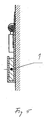
- Figs 5 and 6 a devise comprising a body of permanent magnetic material arranged in a rocker, which takes different positions in dependence of the flow in the pump outlet. If the flow has stopped, the rocker takes a vertical position, Fig 5, while it tilts upwards at a certain flow, Fig 6. The change of the location of the body is registered by the tongue element at the opposite side of the wall in the same way as previously described.
- the solution using a rocker is especially useful when it is expected that the pump might take a position lying down, which brings about a more or less horizontally directed pump outlet and consequently gravity force cannot be relied upon.
- a turning spring connected to the turning axle of the rocker can then be used to secure that the rocker takes its horizontal position when the flow has decreased.
- other variants can be used where the end positions of the rocker are so located, that only a slight turning movement is allowed. This solution may under certain circumstances be less sensitive to disturbances from outside.
Landscapes
- Physics & Mathematics (AREA)
- General Physics & Mathematics (AREA)
- Engineering & Computer Science (AREA)
- Fluid Mechanics (AREA)
- Mechanical Engineering (AREA)
- General Engineering & Computer Science (AREA)
- Structures Of Non-Positive Displacement Pumps (AREA)
- Control Of Non-Positive-Displacement Pumps (AREA)
- Indicating Or Recording The Presence, Absence, Or Direction Of Movement (AREA)
- Measuring Volume Flow (AREA)
Applications Claiming Priority (2)
| Application Number | Priority Date | Filing Date | Title |
|---|---|---|---|
| SE0104317A SE0104317L (sv) | 2001-12-20 | 2001-12-20 | Avkänningsanordning för vätskeflödet i ett pumputlopp avsedd att styra strömtillförseln till den elektriskt drivan pumpmotorn |
| SE0104317 | 2001-12-20 |
Publications (2)
| Publication Number | Publication Date |
|---|---|
| EP1324011A2 true EP1324011A2 (de) | 2003-07-02 |
| EP1324011A3 EP1324011A3 (de) | 2003-11-05 |
Family
ID=20286417
Family Applications (1)
| Application Number | Title | Priority Date | Filing Date |
|---|---|---|---|
| EP02445149A Withdrawn EP1324011A3 (de) | 2001-12-20 | 2002-11-12 | Vorrichtung zum Feststellen des Fliessens einer Flüssigkeit |
Country Status (6)
| Country | Link |
|---|---|
| US (1) | US20030118451A1 (de) |
| EP (1) | EP1324011A3 (de) |
| CN (1) | CN1427181A (de) |
| CA (1) | CA2414307A1 (de) |
| SE (1) | SE0104317L (de) |
| ZA (1) | ZA200209108B (de) |
Cited By (4)
| Publication number | Priority date | Publication date | Assignee | Title |
|---|---|---|---|---|
| US7152469B2 (en) | 2004-01-13 | 2006-12-26 | Baxter International Inc. | Fluid flow sensor, method and system |
| WO2008096103A1 (en) * | 2007-02-07 | 2008-08-14 | Dlp Limited | Shower apparatus for preventing flooding of a shower floor area |
| EP2072829A1 (de) | 2007-12-21 | 2009-06-24 | Grundfos Management A/S | Tauchpumpe |
| IT202100029222A1 (it) * | 2021-11-18 | 2023-05-18 | Guarneri Solutions S R L | Dispositivo per il controllo e l’attivazione di una pompa per lo spostamento di liquidi |
Families Citing this family (2)
| Publication number | Priority date | Publication date | Assignee | Title |
|---|---|---|---|---|
| ATE389807T1 (de) * | 2004-02-11 | 2008-04-15 | Grundfos As | Verfahren zur ermittlung von fehlern beim betrieb eines pumpenaggregates |
| CN107859629A (zh) * | 2017-12-27 | 2018-03-30 | 嘉禾福顺机械实业有限公司 | 一种感应式自动关停自吸泵 |
Family Cites Families (14)
| Publication number | Priority date | Publication date | Assignee | Title |
|---|---|---|---|---|
| DE1276170B (de) * | 1966-10-25 | 1968-08-29 | Honsberg & Co Kg | Stroemungswaechter fuer fluessige oder gasfoermige Medien |
| US3549839A (en) * | 1969-02-26 | 1970-12-22 | Brimco Mfg Co | Fluid flow monitor |
| ES431609A1 (es) * | 1974-11-04 | 1976-10-16 | Wenderoth | Sensor magnetico de flujo de fluidos. |
| US4500759A (en) * | 1983-09-28 | 1985-02-19 | Defasselle Craig R | Fluid flow switch |
| FR2596868B1 (fr) * | 1986-04-08 | 1989-05-05 | Elf Aquitaine | Detecteur d'absence de debit |
| US5222867A (en) * | 1986-08-29 | 1993-06-29 | Walker Sr Frank J | Method and system for controlling a mechanical pump to monitor and optimize both reservoir and equipment performance |
| US4738395A (en) * | 1987-02-17 | 1988-04-19 | Hot Water Equipment Corporation | Fluid flow rate detector and system |
| GB8720412D0 (en) * | 1987-08-28 | 1987-10-07 | Changestart Ltd | Flow detectors |
| BE1002318A6 (nl) * | 1988-07-25 | 1990-11-27 | P D Chemie N V | Kontrole-inrichting voor het debiet van een vloeistof en pompinrichting hiermee uitgerust. |
| US4944190A (en) * | 1988-09-19 | 1990-07-31 | Ametek Corporation | Flow meter |
| US4963857A (en) * | 1989-06-26 | 1990-10-16 | Sackett Robert L | Translatable dual magnets |
| IT1286618B1 (it) * | 1996-05-03 | 1998-07-15 | Lapa Services S R L | Dispositivo per il comando dell'alimentazione di acqua (od altro liquido) mediante pompa e per la protezione della stessa in caso di |
| US5819848A (en) * | 1996-08-14 | 1998-10-13 | Pro Cav Technology, L.L.C. | Flow responsive time delay pump motor cut-off logic |
| US6099264A (en) * | 1998-08-27 | 2000-08-08 | Itt Manufacturing Enterprises, Inc. | Pump controller |
-
2001
- 2001-12-20 SE SE0104317A patent/SE0104317L/xx not_active IP Right Cessation
-
2002
- 2002-11-08 ZA ZA200209108A patent/ZA200209108B/xx unknown
- 2002-11-12 EP EP02445149A patent/EP1324011A3/de not_active Withdrawn
- 2002-11-14 US US10/293,358 patent/US20030118451A1/en not_active Abandoned
- 2002-12-13 CA CA002414307A patent/CA2414307A1/en not_active Abandoned
- 2002-12-13 CN CN02156077.3A patent/CN1427181A/zh active Pending
Cited By (5)
| Publication number | Priority date | Publication date | Assignee | Title |
|---|---|---|---|---|
| US7152469B2 (en) | 2004-01-13 | 2006-12-26 | Baxter International Inc. | Fluid flow sensor, method and system |
| WO2008096103A1 (en) * | 2007-02-07 | 2008-08-14 | Dlp Limited | Shower apparatus for preventing flooding of a shower floor area |
| EP2072829A1 (de) | 2007-12-21 | 2009-06-24 | Grundfos Management A/S | Tauchpumpe |
| US8454330B2 (en) | 2007-12-21 | 2013-06-04 | Grundfos Management A/S | Submersible pump |
| IT202100029222A1 (it) * | 2021-11-18 | 2023-05-18 | Guarneri Solutions S R L | Dispositivo per il controllo e l’attivazione di una pompa per lo spostamento di liquidi |
Also Published As
| Publication number | Publication date |
|---|---|
| SE518821C2 (sv) | 2002-11-26 |
| SE0104317L (sv) | 2002-11-26 |
| EP1324011A3 (de) | 2003-11-05 |
| ZA200209108B (en) | 2003-05-27 |
| CA2414307A1 (en) | 2003-06-20 |
| CN1427181A (zh) | 2003-07-02 |
| US20030118451A1 (en) | 2003-06-26 |
| SE0104317D0 (sv) | 2001-12-20 |
Similar Documents
| Publication | Publication Date | Title |
|---|---|---|
| JP5017665B2 (ja) | ポンプ用制御システム | |
| US20030118451A1 (en) | Device for monitoring fluid flow in a pump outlet | |
| US9410545B2 (en) | Solid state bilge pump switch | |
| US10711474B1 (en) | Pool pumping apparatus | |
| JPS60122266A (ja) | ディ−ゼルエンジン用燃料フィルタ装置 | |
| US9767975B1 (en) | Multiple switch float switch apparatus having a magnetic coupling | |
| CN114087765A (zh) | 一种自动挡水装置及除湿机 | |
| PH12016000100B1 (en) | Air conditioned having temporary drainage function | |
| CN115788919A (zh) | 潜水泵 | |
| KR101351024B1 (ko) | 수위감지장치 및 이를 구비한 공기조화기 | |
| GB2224777A (en) | Apparatus for pumping liquids from containers | |
| JP4283549B2 (ja) | 竪型水中電動ポンプの浸水検知機構 | |
| CN216924722U (zh) | 一种自动挡水装置及除湿机 | |
| JP2009254308A (ja) | 呼び水装置及び該呼び水装置を備えた外部濾過装置 | |
| JP3058137B2 (ja) | 空調機用ドレンアップポンプ | |
| EP1233188A1 (de) | Niveauabhängige Steuerung von Pumpen | |
| AU2025205404B1 (en) | Handheld Swimming Pool Sewage Suction Machine | |
| CN216477899U (zh) | 潜水泵装置 | |
| JPH05321870A (ja) | フローティングポンプ | |
| JP4417471B2 (ja) | 全周水路型水中電動ポンプ | |
| WO2026057182A1 (en) | Water tank for configurable dehumidifier | |
| JPH0633028U (ja) | センサーフランジ | |
| KR20000017162U (ko) | 리드스위치를 이용한 감지기 | |
| CN110273844B (zh) | 一种集成水泵 | |
| JP2579023B2 (ja) | 強制排水装置 |
Legal Events
| Date | Code | Title | Description |
|---|---|---|---|
| PUAI | Public reference made under article 153(3) epc to a published international application that has entered the european phase |
Free format text: ORIGINAL CODE: 0009012 |
|
| 17P | Request for examination filed |
Effective date: 20021122 |
|
| AK | Designated contracting states |
Designated state(s): AT BE BG CH CY CZ DE DK EE ES FI FR GB GR IE IT LI LU MC NL PT SE SK TR |
|
| AX | Request for extension of the european patent |
Extension state: AL LT LV MK RO SI |
|
| PUAL | Search report despatched |
Free format text: ORIGINAL CODE: 0009013 |
|
| RIC1 | Information provided on ipc code assigned before grant |
Ipc: 7G 01F 1/24 B Ipc: 7G 01P 13/00 B Ipc: 7G 01F 1/28 A |
|
| AK | Designated contracting states |
Kind code of ref document: A3 Designated state(s): AT BE BG CH CY CZ DE DK EE ES FI FR GB GR IE IT LI LU MC NL PT SE SK TR |
|
| AX | Request for extension of the european patent |
Extension state: AL LT LV MK RO SI |
|
| AKX | Designation fees paid |
Designated state(s): AT BE BG CH CY CZ DE DK EE ES FI FR GB GR IE IT LI LU MC NL PT SE SK TR |
|
| STAA | Information on the status of an ep patent application or granted ep patent |
Free format text: STATUS: THE APPLICATION IS DEEMED TO BE WITHDRAWN |
|
| 18D | Application deemed to be withdrawn |
Effective date: 20060531 |