EP1324335A2 - Verfahren und Gerät zur Datenaufzeichnung auf ein optisches Aufzeichnungsmedium - Google Patents
Verfahren und Gerät zur Datenaufzeichnung auf ein optisches Aufzeichnungsmedium Download PDFInfo
- Publication number
- EP1324335A2 EP1324335A2 EP02256330A EP02256330A EP1324335A2 EP 1324335 A2 EP1324335 A2 EP 1324335A2 EP 02256330 A EP02256330 A EP 02256330A EP 02256330 A EP02256330 A EP 02256330A EP 1324335 A2 EP1324335 A2 EP 1324335A2
- Authority
- EP
- European Patent Office
- Prior art keywords
- data
- code
- bytes
- recording
- sync
- Prior art date
- Legal status (The legal status is an assumption and is not a legal conclusion. Google has not performed a legal analysis and makes no representation as to the accuracy of the status listed.)
- Ceased
Links
Images



Classifications
-
- G—PHYSICS
- G11—INFORMATION STORAGE
- G11B—INFORMATION STORAGE BASED ON RELATIVE MOVEMENT BETWEEN RECORD CARRIER AND TRANSDUCER
- G11B20/00—Signal processing not specific to the method of recording or reproducing; Circuits therefor
- G11B20/10—Digital recording or reproducing
- G11B20/12—Formatting, e.g. arrangement of data block or words on the record carriers
-
- G—PHYSICS
- G11—INFORMATION STORAGE
- G11B—INFORMATION STORAGE BASED ON RELATIVE MOVEMENT BETWEEN RECORD CARRIER AND TRANSDUCER
- G11B20/00—Signal processing not specific to the method of recording or reproducing; Circuits therefor
- G11B20/10—Digital recording or reproducing
- G11B20/18—Error detection or correction; Testing, e.g. of drop-outs
-
- G—PHYSICS
- G11—INFORMATION STORAGE
- G11B—INFORMATION STORAGE BASED ON RELATIVE MOVEMENT BETWEEN RECORD CARRIER AND TRANSDUCER
- G11B20/00—Signal processing not specific to the method of recording or reproducing; Circuits therefor
- G11B20/10—Digital recording or reproducing
- G11B20/12—Formatting, e.g. arrangement of data block or words on the record carriers
- G11B20/1217—Formatting, e.g. arrangement of data block or words on the record carriers on discs
-
- G—PHYSICS
- G11—INFORMATION STORAGE
- G11B—INFORMATION STORAGE BASED ON RELATIVE MOVEMENT BETWEEN RECORD CARRIER AND TRANSDUCER
- G11B27/00—Editing; Indexing; Addressing; Timing or synchronising; Monitoring; Measuring tape travel
- G11B27/10—Indexing; Addressing; Timing or synchronising; Measuring tape travel
- G11B27/19—Indexing; Addressing; Timing or synchronising; Measuring tape travel by using information detectable on the record carrier
- G11B27/24—Indexing; Addressing; Timing or synchronising; Measuring tape travel by using information detectable on the record carrier by sensing features on the record carrier other than the transducing track ; sensing signals or marks recorded by another method than the main recording
-
- G—PHYSICS
- G11—INFORMATION STORAGE
- G11B—INFORMATION STORAGE BASED ON RELATIVE MOVEMENT BETWEEN RECORD CARRIER AND TRANSDUCER
- G11B7/00—Recording or reproducing by optical means, e.g. recording using a thermal beam of optical radiation by modifying optical properties or the physical structure, reproducing using an optical beam at lower power by sensing optical properties; Record carriers therefor
- G11B7/007—Arrangement of the information on the record carrier, e.g. form of tracks, actual track shape, e.g. wobbled, or cross-section, e.g. v-shaped; Sequential information structures, e.g. sectoring or header formats within a track
- G11B7/00745—Sectoring or header formats within a track
-
- G—PHYSICS
- G11—INFORMATION STORAGE
- G11B—INFORMATION STORAGE BASED ON RELATIVE MOVEMENT BETWEEN RECORD CARRIER AND TRANSDUCER
- G11B7/00—Recording or reproducing by optical means, e.g. recording using a thermal beam of optical radiation by modifying optical properties or the physical structure, reproducing using an optical beam at lower power by sensing optical properties; Record carriers therefor
- G11B7/24—Record carriers characterised by shape, structure or physical properties, or by the selection of the material
- G11B7/2407—Tracks or pits; Shape, structure or physical properties thereof
- G11B7/24085—Pits
-
- G—PHYSICS
- G11—INFORMATION STORAGE
- G11B—INFORMATION STORAGE BASED ON RELATIVE MOVEMENT BETWEEN RECORD CARRIER AND TRANSDUCER
- G11B20/00—Signal processing not specific to the method of recording or reproducing; Circuits therefor
- G11B20/10—Digital recording or reproducing
- G11B20/12—Formatting, e.g. arrangement of data block or words on the record carriers
- G11B20/1217—Formatting, e.g. arrangement of data block or words on the record carriers on discs
- G11B2020/1218—Formatting, e.g. arrangement of data block or words on the record carriers on discs wherein the formatting concerns a specific area of the disc
- G11B2020/1222—ECC block, i.e. a block of error correction encoded symbols which includes all parity data needed for decoding
-
- G—PHYSICS
- G11—INFORMATION STORAGE
- G11B—INFORMATION STORAGE BASED ON RELATIVE MOVEMENT BETWEEN RECORD CARRIER AND TRANSDUCER
- G11B20/00—Signal processing not specific to the method of recording or reproducing; Circuits therefor
- G11B20/10—Digital recording or reproducing
- G11B20/12—Formatting, e.g. arrangement of data block or words on the record carriers
- G11B2020/1264—Formatting, e.g. arrangement of data block or words on the record carriers wherein the formatting concerns a specific kind of data
- G11B2020/1265—Control data, system data or management information, i.e. data used to access or process user data
- G11B2020/1267—Address data
- G11B2020/1269—Absolute time in pregroove [ATIP] information
-
- G—PHYSICS
- G11—INFORMATION STORAGE
- G11B—INFORMATION STORAGE BASED ON RELATIVE MOVEMENT BETWEEN RECORD CARRIER AND TRANSDUCER
- G11B2220/00—Record carriers by type
- G11B2220/20—Disc-shaped record carriers
- G11B2220/21—Disc-shaped record carriers characterised in that the disc is of read-only, rewritable, or recordable type
- G11B2220/215—Recordable discs
-
- G—PHYSICS
- G11—INFORMATION STORAGE
- G11B—INFORMATION STORAGE BASED ON RELATIVE MOVEMENT BETWEEN RECORD CARRIER AND TRANSDUCER
- G11B2220/00—Record carriers by type
- G11B2220/20—Disc-shaped record carriers
- G11B2220/21—Disc-shaped record carriers characterised in that the disc is of read-only, rewritable, or recordable type
- G11B2220/215—Recordable discs
- G11B2220/216—Rewritable discs
-
- G—PHYSICS
- G11—INFORMATION STORAGE
- G11B—INFORMATION STORAGE BASED ON RELATIVE MOVEMENT BETWEEN RECORD CARRIER AND TRANSDUCER
- G11B2220/00—Record carriers by type
- G11B2220/20—Disc-shaped record carriers
- G11B2220/21—Disc-shaped record carriers characterised in that the disc is of read-only, rewritable, or recordable type
- G11B2220/215—Recordable discs
- G11B2220/218—Write-once discs
-
- G—PHYSICS
- G11—INFORMATION STORAGE
- G11B—INFORMATION STORAGE BASED ON RELATIVE MOVEMENT BETWEEN RECORD CARRIER AND TRANSDUCER
- G11B2220/00—Record carriers by type
- G11B2220/20—Disc-shaped record carriers
- G11B2220/25—Disc-shaped record carriers characterised in that the disc is based on a specific recording technology
- G11B2220/2537—Optical discs
- G11B2220/2545—CDs
-
- G—PHYSICS
- G11—INFORMATION STORAGE
- G11B—INFORMATION STORAGE BASED ON RELATIVE MOVEMENT BETWEEN RECORD CARRIER AND TRANSDUCER
- G11B2220/00—Record carriers by type
- G11B2220/20—Disc-shaped record carriers
- G11B2220/25—Disc-shaped record carriers characterised in that the disc is based on a specific recording technology
- G11B2220/2537—Optical discs
- G11B2220/2562—DVDs [digital versatile discs]; Digital video discs; MMCDs; HDCDs
-
- G—PHYSICS
- G11—INFORMATION STORAGE
- G11B—INFORMATION STORAGE BASED ON RELATIVE MOVEMENT BETWEEN RECORD CARRIER AND TRANSDUCER
- G11B2220/00—Record carriers by type
- G11B2220/20—Disc-shaped record carriers
- G11B2220/25—Disc-shaped record carriers characterised in that the disc is based on a specific recording technology
- G11B2220/2537—Optical discs
- G11B2220/2562—DVDs [digital versatile discs]; Digital video discs; MMCDs; HDCDs
- G11B2220/2566—DVDs belonging to the minus family, i.e. -R, -RW, -VR
-
- G—PHYSICS
- G11—INFORMATION STORAGE
- G11B—INFORMATION STORAGE BASED ON RELATIVE MOVEMENT BETWEEN RECORD CARRIER AND TRANSDUCER
- G11B2220/00—Record carriers by type
- G11B2220/20—Disc-shaped record carriers
- G11B2220/25—Disc-shaped record carriers characterised in that the disc is based on a specific recording technology
- G11B2220/2537—Optical discs
- G11B2220/2562—DVDs [digital versatile discs]; Digital video discs; MMCDs; HDCDs
- G11B2220/257—DVDs belonging to the plus family, i.e. +R, +RW, +VR
-
- G—PHYSICS
- G11—INFORMATION STORAGE
- G11B—INFORMATION STORAGE BASED ON RELATIVE MOVEMENT BETWEEN RECORD CARRIER AND TRANSDUCER
- G11B2220/00—Record carriers by type
- G11B2220/20—Disc-shaped record carriers
- G11B2220/25—Disc-shaped record carriers characterised in that the disc is based on a specific recording technology
- G11B2220/2537—Optical discs
- G11B2220/2562—DVDs [digital versatile discs]; Digital video discs; MMCDs; HDCDs
- G11B2220/2575—DVD-RAMs
Definitions
- the present invention relates to a method and an apparatus for recording data on a recordable disc, and more particularly, to a method and an apparatus for recording data on a recordable compact disc at a high density.
- Recordable optical discs include CD-R/RWs of 650 MB, DVD-RAM/R/RWs of 4.7GB, DVD+RWs of 4.7GB, and the like. Also, researches on and the development of HD-DVDs having recording capacity of more than 20GB have been in progress.
- CD-R/RWs are widely used as recordable optical discs. While data can be recorded only one time on CD-Rs, data can be repeatedly rewritten on CD-RWs. However, user data of about 650MB can be recorded on CD-Rs and CD-RWs.
- DVD-RAMs On D-RWs, DVD+RWs, and DVD-RAMs, user data of about 4.7GB can be recorded.
- DVD-RAMs are gradually widespread to general users while recordable DVDs and drives capable of recording user data on DVDs are not yet spread to the general users.
- a method of recording data on an optical recording medium having a plurality of addressable unit areas includes step (a) of recording 62 sync frames, each having a sync code and data, in each of the addressable unit areas.
- a method of recording data on a compact disc having a plurality of physical sector areas which are designated by addressing information pre-recorded when manufacturing the compact disc includes step (a) of recording two physical sectors in each of the physical sector areas.
- step (a) 62 sync frames, each having a sync code and data of 77 bytes, are recorded.
- step (a) includes: (a1) adding an error detecting code to user data and header information; (a2) performing error correction code-encoding; (a3) performing interleaving; (a4) performing channel-modulating; (a5) adding a sync code to a channel bit stream corresponding to data of 77 bytes to generate one sync frame; and (a6) recording 62 sync frames in each of the physical sector areas.
- an error correction code block to which main data of 148 ⁇ 112 bytes, Parity Inner of 6 bytes, and Parity Out of 12 rows are added is generated using Reed-Solomon Product Code.
- step (a3) includes (a31) dividing two error correction code blocks of N1 ⁇ N2 bytes into blocks of "d" bytes that represent the greatest common divisor along a column, respectively; (a32) dividing the object blocks of d ⁇ N1 bytes into d parts along a row and a column, respectively, to obtain partitions of d ⁇ d; and (a33) interleaving data in a predetermined partition by alternatively selecting the two error correction code blocks to obtain a recording block having line-code words of 2 ⁇ N2.
- a recording block having 16 recording units is generated by performing interleaving, and the recording unit has the size of 154 ⁇ 15.5 bytes and includes Parity Outs of 1.5 rows.
- step (a4) data of 1 byte is modulated to 15.3 channel bits, and step (a4) is performed according to a Dual modulation algorithm.
- an apparatus for recording data on a compact disc having a plurality of physical sector areas which are designated by addressing information pre-recorded when manufacturing the compact disc includes an encoding unit, a modulating unit, a sync unit, and a recording unit.
- the encoding unit encodes use data and header information.
- the modulating unit modulates the encoded data to channel bits.
- the sync unit adds a sync code to the modulated data.
- the recording unit records 62 sync frames, each having a sync code and data, in an addressable unit area.
- the encoding unit includes an error detecting code adder, an error correction code encoder, and an interleaver.
- the error detecting code adder adds an error detecting code to the user data and the header information.
- the error correction code encoder error correction code-encodes the user data and the header information to which the error detecting code is added using Reed-Solomon Code to generate an error correction code block.
- the interleaver interleaves the generated error correction code block.
- the error detecting code adder generates a logic sector of 148 ⁇ 14 bytes having user data of 2048 bytes, header information, and an error detecting code
- the error correction code encoder generates an error correction code block of 154 ⁇ 124 bytes in which Parity Inner of 6 bytes and Parity Out of 12 rows are added to eight logic sectors using Reed-Solomon Product Code.
- the interleaver divides first and second error correction code blocks into two parts along the rows of the error correction code blocks and divides two rows along the column of the error detecting code blocks, respectively, to form 56 object blocks each including four partitions and interleaves data so that partitions of the object blocks belonging to the first error correction code block and partitions of the object blocks belonging to the second error correction code block are alternatively selected to generate a recording block.
- the sync unit generates one physical sector which includes 31 sync frames, each having a channel bit stream corresponding to data of 77 bytes and a sync code of 32 channel bits.
- FIGS 1A and 1B are schematic views of a compact disc.
- a spiral track is formed in a recordable compact disc 100.
- the track includes land tracks and groove tracks.
- reference characters G and L represent groove tracks and land tracks, respectively.
- the groove tracks are wobbled by about ⁇ 0.03 ⁇ m toward the radius direction of the recordable compact disc 100.
- Signals detected from the wobbled tracks through a push-pull channel are called "wobble signals".
- a wobble signal includes absolute time information on a disc, i.e., Absolute Time In Pregroove (ATIP) information, a frequency of which is modulated.
- the ATIP information is a kind of address information.
- a physical sector area is determined depending on the ATIP information.
- user data of 2048 bytes (a physical sector) is recorded in "one physical sector area", i.e, "a ATIP sector” while user data of 4096 bytes (two physical sectors) is recorded according to an embodiment of the present invention.
- FIG 2 is a block diagram of a recording apparatus according to a preferred embodiment of the present invention.
- the recording apparatus records data on the compact disc 100 shown in Figures 1A and 1B and includes an encoding unit 1, a modulating unit 2, a sync unit 3, and a recording unit 4.
- the encoding unit 1 encodes user data and header information.
- the modulating unit 2 modulates the encoded data to a channel bit stream.
- the sync unit 3 adds a sync code of a predetermined channel bit to a predetermined position of the modulated channel bit stream.
- the recording unit 4 records the channel bit stream including the sync code on the compact disc 100. Two physical sectors, i.e, 62 sync frames, are recorded in one physical sector area.
- One sync frame is composed of sync codes of a predetermined channel bit and data of 77 bytes.
- FIG 3 is a block diagram of a realization of a recording apparatus based on the design shown in Figure 2.
- the recording apparatus includes an error detecting code (EDC) adder 11, an error correction code (ECC) encoder 12, an interleaver 13, a modulating unit 32, a sync unit 33, and a recording unit 34.
- EDC error detecting code
- ECC error correction code
- the EDC adder 11 adds an EDC to user data and header information to generate a logic sector.
- the ECC encoder 12 generates an ECC block in which parity, i.e., Parity Inner (PI) and Parity Out (PO) are added to a plurality of logic sectors by performing ECC-encoding using Reed-Solomon Product Code.
- Reed-Solomon Product Code is known as correcting multi-errors. However, used codes may vary if necessary.
- the size of the ECC block and the number of bytes which are assigned to PI and PO may also vary.
- the interleaver 13 interleaves two ECC blocks to generate a recording block.
- the interleaver 13 divides first and second ECC blocks into two parts along the rows of the ECC blocks and divides two rows along the column of the EDD blocks, respectively, to form 56 object blocks each including four partitions and interleaves data so that partitions of the object blocks belonging to the first ECC block and partitions of the object blocks belonging to the second ECC block are alternatively selected to generate a recording block. More detailed descriptions will be described later.
- the modulating unit 32 modulates data of 1 byte to 15.3 channel bits according to a Dual modulation algorithm.
- the sync unit 33 adds a sync code of 32 channel bits according to the Dual modulation algorithm to a channel bit stream.
- the Dual modulation algorithm is disclosed in Korean Patent Application No. 99-42032 entitled "Method of Arranging RLL Codes Having Improved DC Suppression Capabilities, Demodulation and Modulation algorithm, and Demodulating Apparatus", filed on September 30, 1999 by the applicant of the present invention and published on November 25, 2000.
- a pair of code groups is arranged such that DC suppression of a code sequence can be controlled; second, signs of a parameter CSV, representing a DC value in a code word of a code corresponding to the same source code in the pair of code groups, and codes (1, 8, 8, 12), arranged so that characteristics of a parameter INV for estimating a Digital Sum Value (DSV) transition direction of a next code word are opposite to one another, are used.
- a parameter CSV representing a DC value in a code word of a code corresponding to the same source code in the pair of code groups, and codes (1, 8, 8, 12), arranged so that characteristics of a parameter INV for estimating a Digital Sum Value (DSV) transition direction of a next code word are opposite to one another, are used.
- DSV Digital Sum Value
- the recording unit 34 records two physical sectors in one ATIP sector.
- One physical sector includes 31 sync frames.
- one sync frame is composed of a sync code of 32 channel bits and data of 77 bytes. The detailed structure of one physical sector will be described later.
- Figure 4 shows the configuration of one logic sector.
- one logic sector generated by the ECC adder 11 has the size of 148 ⁇ 14 bytes according to this embodiment and is composed of user data of 2048 bytes, header information of 20 bytes, and an EDC of 4 bytes.
- FIGs 5 and 6 show the configurations of an ECC block.
- the ECC encoder 12 generates the ECC block of 154 ⁇ 124 bytes by adding PI and PO to eight logic sectors which was described with reference to Figure 4.
- a code word of data of 148 bytes and PI of 6 bytes is arranged along a row and code words of 112 rows are arranged along a column with PO of 12 rows.
- Figures 7 and 11 are reference views for explaining interleaving according to the present invention. Referring to Figures 7 and 8, assuming that ECC blocks A and B are composed data of N 1 bytes along the row and data of N 2 bytes along the column, respectively, the interleaving is performed as follows.
- ECC blocks A and B are divided into “d” blocks along a column.
- "d” is a common divisor of N 1 and N 2 .
- the divided several blocks are called “object blocks”.
- the interleaving according to this embodiment is performed in the respective object blocks "a” and "b” of ECC blocks A and B.
- object blocks "a” and “b” are divided along a column based on each line, respectively.
- object blocks "a” and “b” are divided into partitions of d x d, respectively.
- partitions of 2 ⁇ d ⁇ d are created from object blocks "a" and "b". These partitions are 1_1, 1_2, .., 1_2, ⁇ d, 2_1, 2_2, .., 2_2 ⁇ d, .., d_1, d_2, .., d_2 ⁇ d, each having data of N 1 /d bytes.
- first data is extracted from partition 1_1
- second data is extracted from partition 1_2, .., 2 ⁇ d th data is extracted from partition 1_2 ⁇ d
- 2 ⁇ d + 1 th data is extracted from partition 1_1
- 2 ⁇ d + 2 th data is extracted from partition 1_2, .., and 2 ⁇ d + 2 ⁇ d th data is extracted from partition 1_2 ⁇ d.
- data is extracted from all of 1_1, 1_2, .., 1_2 ⁇ d, and then data is alternatively extracted from 2_1, 2_2, .., 2_2 ⁇ d.
- the created block is composed of data of 2 ⁇ (N 2 - k2) and an outer parity of 2 ⁇ k2.
- Figures recorded along the rows of the block represent consecutive numbers that are allotted to byte data of each partition.
- the byte data is arranged in the order shown in Figure 9.
- Partition 1_1 When the remainder N 1 /d of 1, ..., 2 ⁇ N1 divided by 2 ⁇ d is 1.
- Partition 1_2 When the remainder N 1 /d of 1, ..., 2 ⁇ N1 divided by 2 ⁇ d is 2.
- ... Partition 1_2 ⁇ d When the remainder N 1 /d of 1, ..., 2 x N1 divided by 2 ⁇ d is 0.
- Partition 2_1 When the remainder N 1 /d of 2 ⁇ N 1 + 1, ..., 2 ⁇ N 1 + 2 ⁇ N 1 divided by 2 ⁇ d is 1.
- Partition 2_2 When the remainder N 1 /d of 2 ⁇ N 1 + 1, ..., 2 ⁇ N 1 + 2 ⁇ N 1 divided by 2 ⁇ d is 2.
- Partition 2_2 ⁇ d When the remainder N 1 /d of 2 ⁇ N 1 + 1, ..., 2 ⁇ N 1 + 2 ⁇ N 1 divided by 2 ⁇ d is 0.
- Partition d_1 When the remainder N 1 /d of (d-1) ⁇ 2 ⁇ N 1 + 1, ..., d ⁇ 2 ⁇ N 1 divided by 2 ⁇ d is 1.
- Partition d_2 When the remainder N 1 /d of (d-1) ⁇ 2 ⁇ N 1 + 1, ..., d ⁇ 2 ⁇ N 1 divided by 2 ⁇ d is 2 ...
- Partition d_2 ⁇ d When the remainder N 1 /d of (d-1) ⁇ 2 ⁇ N 1 + 1, ..., d ⁇ 2 ⁇ N 1 divided by 2 ⁇ d is 0.
- Partition m_n When the remainder N 1 /d of 2 ⁇ N 1 (m-1) +1, ..., 2 ⁇ m ⁇ N 1 divided by 2 ⁇ d is n.
- partition 1_1 has data of N1/d bytes, first byte of which is given 1, second byte of which is given 1+2d, third byte of which is given 1+4d, ..., (N1/d)-1 th byte of which is given 1+2N1-4d, and N1/d th byte of which is given 1+2N1-2d.
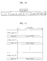
- Figure 11 schematically shows a recording block rearranged based on the block of Figure 9.
- the recording block is created by inserting PO of 2 ⁇ k2 in the block of Figure 9 at every 2 ⁇ k2/16 lines.
- Figure 12 is a view for explaining a process of creating a recording block by performing interleaving in ECC blocks A and B.
- object blocks "a” and “b” have eight partitions (1), (2), (3), (4), (5), (6), (7), and (8), respectively.
- Object block "a” belongs to ECC block A and object block "b” belongs to ECC block "b”.
- Partition (1) has data 1, 5, 9, .., 305
- partition (2) has data of 309, .., 613
- partition (3) has data of 2, 6, 10, .., 306.
- partition (4) has data of 310, .., 614, partition (5) has data of 311, .., 615, partition (6) has data of 3, 7, 11, .., 307, partition (7) has data of 312, .., 616, and partition (8) has data of 4, 8, 12, .., 308.
- first data is extracted from partition (1)
- second data is extracted from partition (3)
- third data is extracted from partition (6)
- fourth data is extracted from partition (8).
- Fifth data is extracted from partition (1)
- sixth data is extracted from partition (3)
- seventh data is extracted from partition (6)
- eighth data is extracted from partition (8).
- data is alternatively extracted from partitions (2), (4), (5), and (7). This process is repeated at every two lines.
- POs of ECC blocks A and B are 24 lines, respectively, POs of 1.5 lines are equally distributed to each recording unit. As a result, the recording block is created.
- the recording block is composed of 16 recording units. Each of the recording units has a size of 154 ⁇ 15.5 bytes.
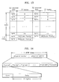
- Figure 13 shows the configuration of one physical sector.
- one physical sector is composed of data corresponding to one recording unit of Figure 12 including 77 bytes and sync codes.
- each sync code is composed of 32 channel bits according to a Dual coding method.
- a sync code of 32 channel bits and data of 77 bytes form one sync frame
- one sector data is composed of 31 sync frames.
- the number of channel bits being assigned to the sync codes and the sync codes may vary.
- Figure 14 shows the configuration of data that is recorded in an addressable unit area.
- two physical sectors are recorded in on physical sector that is one addressable unit area of the recordable compact disc.
- Each of the physical sectors is composed of 31 sync frames.
- Each sync frame is composed of a sync code of 32 channel bits and user data of 77 bytes.
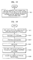
- Figure 15 is a flowchart for explaining a method of recording data according to the present invention.
- the recording apparatus records two physical sectors, i.e., 62 sync frames, each having a sync code of 32 channel bits and data of 77 bytes, in one physical sector area which is designated by addressing information pre-recorded when manufacturing the recordable compact disc.
- FIG 16 is a flowchart for explaining a recording data according to the embodiment.
- the EDC adder 11 of the recording apparatus adds an EDC to user data of 2048 bytes and header information to generate one logic sector.
- the ECC encoder 12 generates an ECC block of 154 ⁇ 124 bytes to which PI of 6 bytes and PO of 12 rows are added by performing ECC-encoding using Reed-Solomon Product Code.
- the interleaver 13 performs interleaving in two ECC blocks to generate a recording block having 16 recording units.
- the modulating unit 32 modulates data of 1 byte to 15.3 channel bits according to the Dual modulation algorithm.
- step 1605 the sync unit 33 adds a sync code of 32 channel bits to a channel bit stream according to the Dual modulation algorithm.
- step 1606 the recording unit 34 records two physical sectors, i.e., 62 sync frames, in one physical sector area according to the present invention.
- user data can be recorded on a recordable optical disc, particularly a recordable compact disc, at a higher density.
- EFM Eight-to-Fourteen Modulation
- data of 57624 channel bits (about 3390 bytes)
- two physical sectors are recorded in one ATIP sector and data of 2449 bytes (a sync code of 32 channel bits (2 bytes) + header information of 20 bytes + user data of 2048 bytes + an EDC of 4 bytes) is recorded in each of the physical sectors.
- the recordable compact disc according to this embodiment of the present invention has recording density 1.384 (3390/2449) times higher than the conventional recordable compact disc.
- data of 8 bytes is modulated to 17 channel bits according to the Dual modulation algorithm while in the present invention, data of 8 bytes is modulated to 15.3 channel bits.
- recording density can increase by about 1.1 times.
- MML minimum mark length
- recording density can increase by 1.33 times.
- the Dual modulation algorithm is used with the reduction in the MML, 2.04 times higher recording density can be obtained.
- the reduction in the MML is possible within the limit of guaranteeing reproduction quality.
- ECC blocks and the interleaving of the present invention since the correction rate of burst errors increases, reproduction quality can be guaranteed to some extent although the MML is reduced to 0.627 ⁇ m.
Landscapes
- Engineering & Computer Science (AREA)
- Signal Processing (AREA)
- Signal Processing For Digital Recording And Reproducing (AREA)
- Optical Recording Or Reproduction (AREA)
Applications Claiming Priority (2)
| Application Number | Priority Date | Filing Date | Title |
|---|---|---|---|
| KR1020010080014A KR100833227B1 (ko) | 2001-12-17 | 2001-12-17 | 광 기록매체에 데이터를 기록하는 방법 및 장치 |
| KR2001080014 | 2001-12-17 |
Publications (2)
| Publication Number | Publication Date |
|---|---|
| EP1324335A2 true EP1324335A2 (de) | 2003-07-02 |
| EP1324335A3 EP1324335A3 (de) | 2006-11-02 |
Family
ID=19717120
Family Applications (1)
| Application Number | Title | Priority Date | Filing Date |
|---|---|---|---|
| EP02256330A Ceased EP1324335A3 (de) | 2001-12-17 | 2002-09-12 | Verfahren und Gerät zur Datenaufzeichnung auf ein optisches Aufzeichnungsmedium |
Country Status (6)
| Country | Link |
|---|---|
| US (1) | US7062699B2 (de) |
| EP (1) | EP1324335A3 (de) |
| JP (1) | JP2003208763A (de) |
| KR (1) | KR100833227B1 (de) |
| CN (1) | CN1303592C (de) |
| TW (1) | TWI229321B (de) |
Cited By (1)
| Publication number | Priority date | Publication date | Assignee | Title |
|---|---|---|---|---|
| EP1324323A3 (de) * | 2001-12-18 | 2007-05-09 | Samsung Electronics Co., Ltd. | Verfahren und Vorrichtung zur Aufzeichnung auf ein schreibares Compact-Disc |
Families Citing this family (2)
| Publication number | Priority date | Publication date | Assignee | Title |
|---|---|---|---|---|
| JP2003318865A (ja) * | 2002-04-26 | 2003-11-07 | Fuji Xerox Co Ltd | 信号伝送システム |
| JP2004253099A (ja) * | 2003-02-21 | 2004-09-09 | Toshiba Corp | シンクフレーム構造、情報記憶媒体、情報記録方法、情報再生方法、および情報再生装置 |
Citations (3)
| Publication number | Priority date | Publication date | Assignee | Title |
|---|---|---|---|---|
| EP1067553A2 (de) | 1999-07-06 | 2001-01-10 | Fujitsu Limited | Aufzeichnungsmedium und Informationsaufzeichnungsgerät |
| EP1089271A2 (de) | 1999-09-29 | 2001-04-04 | Sony Corporation | BCD Subcode Zeitinformation |
| EP1146513A2 (de) | 2000-04-14 | 2001-10-17 | Sony Corporation | Datenaufzeichnung und -wiedergabe |
Family Cites Families (9)
| Publication number | Priority date | Publication date | Assignee | Title |
|---|---|---|---|---|
| DE69615548T2 (de) * | 1995-04-10 | 2002-05-29 | Kabushiki Kaisha Toshiba, Kawasaki | Optischer aufzeichnungsträger und verfahren zur aufzeichnung und wiedergabe dessen signalen |
| JP3951317B2 (ja) * | 1995-09-28 | 2007-08-01 | ソニー株式会社 | データ記録/再生のための装置および方法 |
| JP3586041B2 (ja) * | 1996-04-26 | 2004-11-10 | 株式会社東芝 | 記録データ生成方法およびデータ再生装置 |
| KR100565046B1 (ko) | 1999-04-21 | 2006-03-30 | 삼성전자주식회사 | 개선된 dc 억압 능력을 갖는 rll 코드 배치 방법, 변복조 방법 및 복조 장치 |
| US6281816B1 (en) * | 1999-08-24 | 2001-08-28 | International Business Machines Corporation | Method and apparatus for reducing data expansion during data compression |
| JP2001101806A (ja) * | 1999-09-27 | 2001-04-13 | Hitachi Ltd | ディジタル信号記録方法、及びその装置、記録媒体 |
| KR100714019B1 (ko) * | 2001-03-12 | 2007-05-04 | 엘지전자 주식회사 | 기록매체 및 기록방법 |
| KR100739669B1 (ko) | 2001-04-20 | 2007-07-13 | 삼성전자주식회사 | 광 정보저장 매체, 데이터 기록장치 및 데이터 기록방법 |
| KR100896681B1 (ko) * | 2001-12-18 | 2009-05-14 | 삼성전자주식회사 | 컴팩트 디스크에 데이터를 기록하는 방법 및 그 장치 |
-
2001
- 2001-12-17 KR KR1020010080014A patent/KR100833227B1/ko not_active Expired - Fee Related
-
2002
- 2002-09-05 TW TW091120254A patent/TWI229321B/zh active
- 2002-09-12 EP EP02256330A patent/EP1324335A3/de not_active Ceased
- 2002-10-09 CN CNB021443130A patent/CN1303592C/zh not_active Expired - Fee Related
- 2002-12-05 JP JP2002354229A patent/JP2003208763A/ja active Pending
- 2002-12-17 US US10/320,739 patent/US7062699B2/en not_active Expired - Fee Related
Patent Citations (3)
| Publication number | Priority date | Publication date | Assignee | Title |
|---|---|---|---|---|
| EP1067553A2 (de) | 1999-07-06 | 2001-01-10 | Fujitsu Limited | Aufzeichnungsmedium und Informationsaufzeichnungsgerät |
| EP1089271A2 (de) | 1999-09-29 | 2001-04-04 | Sony Corporation | BCD Subcode Zeitinformation |
| EP1146513A2 (de) | 2000-04-14 | 2001-10-17 | Sony Corporation | Datenaufzeichnung und -wiedergabe |
Cited By (2)
| Publication number | Priority date | Publication date | Assignee | Title |
|---|---|---|---|---|
| EP1324323A3 (de) * | 2001-12-18 | 2007-05-09 | Samsung Electronics Co., Ltd. | Verfahren und Vorrichtung zur Aufzeichnung auf ein schreibares Compact-Disc |
| US7327659B2 (en) | 2001-12-18 | 2008-02-05 | Samsung Electronics Co., Ltd. | Method and apparatus for recording data on writable compact disc |
Also Published As
| Publication number | Publication date |
|---|---|
| JP2003208763A (ja) | 2003-07-25 |
| EP1324335A3 (de) | 2006-11-02 |
| CN1303592C (zh) | 2007-03-07 |
| US7062699B2 (en) | 2006-06-13 |
| US20030131309A1 (en) | 2003-07-10 |
| KR20030049713A (ko) | 2003-06-25 |
| TWI229321B (en) | 2005-03-11 |
| KR100833227B1 (ko) | 2008-05-28 |
| CN1427397A (zh) | 2003-07-02 |
Similar Documents
| Publication | Publication Date | Title |
|---|---|---|
| EP1304698B1 (de) | Plattenaufzeichnungsmedium, Plattenantriebsgerät und Wiedergabeverfahren | |
| CN100428353C (zh) | 信息记录介质,信息再现设备,信息再现方法以及信息记录方法 | |
| US20080144479A1 (en) | Optical disc and its information recording method and apparatus | |
| JP2002319242A (ja) | 記録方法、記録装置、伝送装置、再生方法、再生装置、受信装置、記録媒体及び伝送媒体 | |
| CN100409345C (zh) | 信息记录方法、信息再现方法、信息再现设备 | |
| EP1486956A1 (de) | Informationsaufteilungsmedium und informationsaufzeichnungs-/-wiedergabeeinrichtung und verfahren | |
| JP3782398B2 (ja) | 光ディスク媒体および光ディスク記録装置及び再生装置 | |
| JP4658075B2 (ja) | データ記録方法及び装置 | |
| EP1324335A2 (de) | Verfahren und Gerät zur Datenaufzeichnung auf ein optisches Aufzeichnungsmedium | |
| US20060218464A1 (en) | Optical information recording medium and data recording apparatus thereon | |
| EP1251510B1 (de) | Optisches Informationsaufzeichnungsmedium und Datenaufzeichnungsgerät | |
| JP2006190483A (ja) | 光ディスクとその情報記録方法及び装置 | |
| JPH08329616A (ja) | データ記録/再生装置および方法、並びにデータ記録媒体 |
Legal Events
| Date | Code | Title | Description |
|---|---|---|---|
| PUAI | Public reference made under article 153(3) epc to a published international application that has entered the european phase |
Free format text: ORIGINAL CODE: 0009012 |
|
| 17P | Request for examination filed |
Effective date: 20020930 |
|
| AK | Designated contracting states |
Designated state(s): AT BE BG CH CY CZ DE DK EE ES FI FR GB GR IE IT LI LU MC NL PT SE SK TR |
|
| AX | Request for extension of the european patent |
Extension state: AL LT LV MK RO SI |
|
| RIN1 | Information on inventor provided before grant (corrected) |
Inventor name: JU, YOUNG-IM Inventor name: RUY, SANG-HYUN Inventor name: HAN, SUNG-HYU Inventor name: LEE, YOON-WOO Inventor name: HWANG, SUNG-HEE |
|
| PUAL | Search report despatched |
Free format text: ORIGINAL CODE: 0009013 |
|
| AK | Designated contracting states |
Kind code of ref document: A3 Designated state(s): AT BE BG CH CY CZ DE DK EE ES FI FR GB GR IE IT LI LU MC NL PT SE SK TR |
|
| AX | Request for extension of the european patent |
Extension state: AL LT LV MK RO SI |
|
| AKX | Designation fees paid |
Designated state(s): DE FR GB NL |
|
| 17Q | First examination report despatched |
Effective date: 20071116 |
|
| STAA | Information on the status of an ep patent application or granted ep patent |
Free format text: STATUS: THE APPLICATION HAS BEEN REFUSED |
|
| 18R | Application refused |
Effective date: 20110707 |