EP1324461A2 - Bobinage pour machine électrique tournante, procédé de fabrication dudit bobinage, et procédé de fabrication d'une machine électrique tournante utilisant ledit bobinage - Google Patents
Bobinage pour machine électrique tournante, procédé de fabrication dudit bobinage, et procédé de fabrication d'une machine électrique tournante utilisant ledit bobinage Download PDFInfo
- Publication number
- EP1324461A2 EP1324461A2 EP02028842A EP02028842A EP1324461A2 EP 1324461 A2 EP1324461 A2 EP 1324461A2 EP 02028842 A EP02028842 A EP 02028842A EP 02028842 A EP02028842 A EP 02028842A EP 1324461 A2 EP1324461 A2 EP 1324461A2
- Authority
- EP
- European Patent Office
- Prior art keywords
- conductor
- slot
- straight
- portions
- segment
- Prior art date
- Legal status (The legal status is an assumption and is not a legal conclusion. Google has not performed a legal analysis and makes no representation as to the accuracy of the status listed.)
- Granted
Links
Images






Classifications
-
- H—ELECTRICITY
- H02—GENERATION; CONVERSION OR DISTRIBUTION OF ELECTRIC POWER
- H02K—DYNAMO-ELECTRIC MACHINES
- H02K3/00—Details of windings
- H02K3/04—Windings characterised by the conductor shape, form or construction, e.g. with bar conductors
- H02K3/12—Windings characterised by the conductor shape, form or construction, e.g. with bar conductors arranged in slots
-
- H—ELECTRICITY
- H02—GENERATION; CONVERSION OR DISTRIBUTION OF ELECTRIC POWER
- H02K—DYNAMO-ELECTRIC MACHINES
- H02K15/00—Processes or apparatus specially adapted for manufacturing, assembling, maintaining or repairing of dynamo-electric machines
- H02K15/06—Embedding prefabricated windings in the machines
- H02K15/062—Windings in slots; Salient pole windings
- H02K15/064—Windings consisting of separate segments
-
- H—ELECTRICITY
- H02—GENERATION; CONVERSION OR DISTRIBUTION OF ELECTRIC POWER
- H02K—DYNAMO-ELECTRIC MACHINES
- H02K15/00—Processes or apparatus specially adapted for manufacturing, assembling, maintaining or repairing of dynamo-electric machines
- H02K15/04—Processes or apparatus specially adapted for manufacturing, assembling, maintaining or repairing of dynamo-electric machines of windings prior to their mounting into the machines
- H02K15/0414—Processes or apparatus specially adapted for manufacturing, assembling, maintaining or repairing of dynamo-electric machines of windings prior to their mounting into the machines the windings consisting of separate elements, e.g. bars, segments or half coils
- H02K15/0421—Processes or apparatus specially adapted for manufacturing, assembling, maintaining or repairing of dynamo-electric machines of windings prior to their mounting into the machines the windings consisting of separate elements, e.g. bars, segments or half coils and consisting of single conductors, e.g. hairpins
- H02K15/0428—Processes or apparatus for simultaneously twisting two or more hairpins
-
- H—ELECTRICITY
- H02—GENERATION; CONVERSION OR DISTRIBUTION OF ELECTRIC POWER
- H02K—DYNAMO-ELECTRIC MACHINES
- H02K15/00—Processes or apparatus specially adapted for manufacturing, assembling, maintaining or repairing of dynamo-electric machines
- H02K15/06—Embedding prefabricated windings in the machines
-
- H—ELECTRICITY
- H02—GENERATION; CONVERSION OR DISTRIBUTION OF ELECTRIC POWER
- H02K—DYNAMO-ELECTRIC MACHINES
- H02K15/00—Processes or apparatus specially adapted for manufacturing, assembling, maintaining or repairing of dynamo-electric machines
- H02K15/20—Shaping or compacting conductors or winding heads after the installation of the winding in the cores or machines; Applying fastening means on winding heads
- H02K15/24—Shaping or compacting winding heads
-
- Y—GENERAL TAGGING OF NEW TECHNOLOGICAL DEVELOPMENTS; GENERAL TAGGING OF CROSS-SECTIONAL TECHNOLOGIES SPANNING OVER SEVERAL SECTIONS OF THE IPC; TECHNICAL SUBJECTS COVERED BY FORMER USPC CROSS-REFERENCE ART COLLECTIONS [XRACs] AND DIGESTS
- Y10—TECHNICAL SUBJECTS COVERED BY FORMER USPC
- Y10T—TECHNICAL SUBJECTS COVERED BY FORMER US CLASSIFICATION
- Y10T29/00—Metal working
- Y10T29/49—Method of mechanical manufacture
- Y10T29/49002—Electrical device making
- Y10T29/49009—Dynamoelectric machine
-
- Y—GENERAL TAGGING OF NEW TECHNOLOGICAL DEVELOPMENTS; GENERAL TAGGING OF CROSS-SECTIONAL TECHNOLOGIES SPANNING OVER SEVERAL SECTIONS OF THE IPC; TECHNICAL SUBJECTS COVERED BY FORMER USPC CROSS-REFERENCE ART COLLECTIONS [XRACs] AND DIGESTS
- Y10—TECHNICAL SUBJECTS COVERED BY FORMER USPC
- Y10T—TECHNICAL SUBJECTS COVERED BY FORMER US CLASSIFICATION
- Y10T29/00—Metal working
- Y10T29/49—Method of mechanical manufacture
- Y10T29/49002—Electrical device making
- Y10T29/49009—Dynamoelectric machine
- Y10T29/49011—Commutator or slip ring assembly
-
- Y—GENERAL TAGGING OF NEW TECHNOLOGICAL DEVELOPMENTS; GENERAL TAGGING OF CROSS-SECTIONAL TECHNOLOGIES SPANNING OVER SEVERAL SECTIONS OF THE IPC; TECHNICAL SUBJECTS COVERED BY FORMER USPC CROSS-REFERENCE ART COLLECTIONS [XRACs] AND DIGESTS
- Y10—TECHNICAL SUBJECTS COVERED BY FORMER USPC
- Y10T—TECHNICAL SUBJECTS COVERED BY FORMER US CLASSIFICATION
- Y10T29/00—Metal working
- Y10T29/49—Method of mechanical manufacture
- Y10T29/49002—Electrical device making
- Y10T29/49009—Dynamoelectric machine
- Y10T29/49012—Rotor
-
- Y—GENERAL TAGGING OF NEW TECHNOLOGICAL DEVELOPMENTS; GENERAL TAGGING OF CROSS-SECTIONAL TECHNOLOGIES SPANNING OVER SEVERAL SECTIONS OF THE IPC; TECHNICAL SUBJECTS COVERED BY FORMER USPC CROSS-REFERENCE ART COLLECTIONS [XRACs] AND DIGESTS
- Y10—TECHNICAL SUBJECTS COVERED BY FORMER USPC
- Y10T—TECHNICAL SUBJECTS COVERED BY FORMER US CLASSIFICATION
- Y10T29/00—Metal working
- Y10T29/49—Method of mechanical manufacture
- Y10T29/49002—Electrical device making
- Y10T29/4902—Electromagnet, transformer or inductor
- Y10T29/49071—Electromagnet, transformer or inductor by winding or coiling
-
- Y—GENERAL TAGGING OF NEW TECHNOLOGICAL DEVELOPMENTS; GENERAL TAGGING OF CROSS-SECTIONAL TECHNOLOGIES SPANNING OVER SEVERAL SECTIONS OF THE IPC; TECHNICAL SUBJECTS COVERED BY FORMER USPC CROSS-REFERENCE ART COLLECTIONS [XRACs] AND DIGESTS
- Y10—TECHNICAL SUBJECTS COVERED BY FORMER USPC
- Y10T—TECHNICAL SUBJECTS COVERED BY FORMER US CLASSIFICATION
- Y10T29/00—Metal working
- Y10T29/49—Method of mechanical manufacture
- Y10T29/49002—Electrical device making
- Y10T29/4902—Electromagnet, transformer or inductor
- Y10T29/49073—Electromagnet, transformer or inductor by assembling coil and core
-
- Y—GENERAL TAGGING OF NEW TECHNOLOGICAL DEVELOPMENTS; GENERAL TAGGING OF CROSS-SECTIONAL TECHNOLOGIES SPANNING OVER SEVERAL SECTIONS OF THE IPC; TECHNICAL SUBJECTS COVERED BY FORMER USPC CROSS-REFERENCE ART COLLECTIONS [XRACs] AND DIGESTS
- Y10—TECHNICAL SUBJECTS COVERED BY FORMER USPC
- Y10T—TECHNICAL SUBJECTS COVERED BY FORMER US CLASSIFICATION
- Y10T29/00—Metal working
- Y10T29/53—Means to assemble or disassemble
- Y10T29/5313—Means to assemble electrical device
- Y10T29/53143—Motor or generator
Definitions
- the present invention relates to a coil for an electric rotary machine and its manufacturing method, and more particularly to a stator of an automotive electric rotary machine equipped with a coil consisting of serially joined conductor segments and its manufacturing method. Furthermore, the present invention relates to a method for manufacturing an electric rotary machine using this coil.
- a conventionally proposed stator coil consists of numerous conductor segments which are inserted into slots of a stator and serially joined each other.
- Japanese patent No. 3118837 corresponding to United States Patent No. 6,249,956
- Japanese patent No. 3196738 corresponding to United States Patent Application publication No. 2002/0053126
- a pair of legs of a conductor segment are separately inserted into different slots of a rotor spaced by an angle equivalent to a pole pitch.
- a protruding part of each leg is bent in the circumferential direction. Then, the distal ends of the legs of different conductor segments are successively joined.
- the conductor segment consists of a U-shaped (more accurately, a V-shaped) head conductor portion, a pair of in-slot conductor portions extending from both ends of the head conductor portion and inserted into different slots from one axial side of a core, and a pair of tail conductor portions protruding out of the slots from the other axial side of the core and extending in the circumferential directions.
- the distal ends of the tail conductor portions of different conductor segments are joined together.
- the in-slot conductor portion and the tail conductor portion may be collectively referred to as a leg of the conductor segment.
- the head conductor portions of respective conductor segments cooperatively constitute a first coil end (i.e., a head side coil end).
- the tail conductor portions of respective conductor segments cooperatively constitute a second coil end (i.e., a tail side coil end).
- Each prepared pine-needle conductor segment has two elongated legs neighboring to each other and extending straight from its head.
- each pine-needle conductor segment is configured into a U-shaped conductor segment with a pair of in-slot conductor portions angularly spaced by one pole pitch in the circumferential direction.
- the U-shaped conductor segments are spatially disposed (more specifically, aligned in the circumferential direction) so that a required number of conductor segments are simultaneously inserted into each slot of the stator core.
- a pair of coaxial rings having insertion holes for example, disclosed in Fig. 3 of Japanese Patent No. 3118837.
- both legs of a pine-needle conductor segment are inserted into two adjacent holes of the coaxial rings which are positioned in the same angular position. Then, the coaxial rings are mutually rotated about their axes by the amount corresponding to one pole pitch in the circumferential direction.
- each pine-needle conductor segment is configured into a U-shaped conductor segment with a head portion straddling so as to form, as a whole, a U shape in the circumferential direction.
- a process for inserting each conductor segment, formed into a U-shaped configuration and aligned in the circumferential direction, into a slot of the core is performed. This process is performed by pulling the legs out of the rings having insertion holes, while holding the head conductor portions of respective conductor segments each being formed into a U-shaped configuration and aligned in the circumferential direction, and then inserting the legs of respective conductor segments into slots of the core.
- each tail conductor portion is bent in the circumferential direction by a half pole pitch.
- Such circumferential bending process is performed by using a plurality of coaxial rings having insertion holes, for example, disclosed in Figs. 4 and 5 of Japanese Patent No. 31967398.
- the distal ends of tail conductor portions are inserted into insertion holes of the coaxial rings.
- each coaxial ring is rotated in the circumferential direction by a half pole pitch (electric angle of ⁇ /2), so that each tail conductor portion is bent in the circumferential direction by a half pole pitch.
- the curvature at the bend point can be enlarged.
- the small U-shaped turning conductor segment and the large U-shaped turning conductor segment are accommodated in the same slot in such a manner that a total of four in-slot conductor portions are aligned in the radial direction.
- the in-slot conductor of the innermost layer and the in-slot conductor of the outermost layer are mutually connected via a head conductor portion of a large U-shaped turning conductor segment.
- the in-slot conductor of the inner middle layer and the in-slot conductor of the outer middle layer are mutually connected via a head conductor portion of a small U-shaped turning conductor segment.
- the distal end of a tail conductor portion of the innermost layer is welded to the distal end of a tail conductor portion of the inner middle layer.
- the distal end of a tail conductor portion of the outermost layer is welded to the distal end of a tail conductor portion of the outer middle layer.
- the slot layout is expressed by U, X, ⁇ V, ⁇ Z, W, Y, ⁇ U, ⁇ X, V, Z, ⁇ W, and ⁇ Y.
- the mutually neighboring U-phase and X-phase coils are serially connected with a neutral point at one end and a U-X output terminal at the other end.
- the mutually neighboring W-phase and Y-phase coils are serially connected with a neutral point at one end and a W-Y output terminal at the other end.
- the mutually neighboring V-phase and Z-phase coils are serially connected with a neutral point at one end and a V-Z output terminal at the other end.
- the U-shaped head conductor portion of the U-shaped conductor segment is sharply bent at an opening of the slot through which the conductor segment is inserted.
- the U-shaped conductor segment inclines in the circumferential direction.
- an insulating resin film covering the surface of the conductor segment directly faces the sharp edge of the slot opening.
- an insulating sheet intervenes between the core and the conductor segment so as to insulate the in-slot conductor portion from the inner surface of the slot.
- surface discharge occurs between neighboring conductor segments. Considering this fact, it is very important to improve electric insulation properties of the U-shaped head conductor portion of each conductor segment whose roots are bent at the slot opening.
- the head side coil end is constituted by U-shaped head conductor portions which are bent in the circumferential direction at the portion very close to the slot opening.
- This arrangement significantly reduces a clearance for cooling air flowing in the radial direction.
- a circumferential cross-sectional area available for the cooling air is insufficient at a portion adjacent to the end surface of the core. Hence, the cooling ability of the core is worse.
- the cooling ability of the coil is a decisive factor for an advanced electric rotary machine which is compact in size and large in output power.
- the cooling ability of the coil is greatly dependent on the coil ends because heat exchange between the coil and the cooling air is chiefly performed at the coil ends.
- the cooling surfaces of the coil end is roughly proportional to the longitudinal length of the coil end. Accordingly, to improve the cooling ability of the coil, it is necessary to increase the longitudinal length (i.e., extension length) of each U-shaped head conductor portion. However, this leads to undesirable increase in the axial length of the head side coil end and will result in a significant scale-up in the size as well as in the weight of a resulting rotary machine.
- the present invention provides a coil for an electric rotary machine including a plurality of conductor segments each having a V-shaped head conductor portion, a pair of in-slot conductor portions extending from both ends of the head conductor portion and accommodated in two different slots of a core, and a pair of tail conductor portions continuing from the in-slot conductor portions and protruding out of axially opposite openings of the slots and extending at least in a circumferential direction.
- the conductor segments are successively connected by joining distal ends of the tail conductor portions.
- the head conductor portion of each conductor segment constitutes part of a head side coil end of the coil.
- each conductor segment constitutes part of a tail side coil end of the coil.
- the head conductor portion or the tail conductor portion includes a V-angled portion and straight portions.
- Each V-angled portion includes an apex positioned farthest in an axial direction from the core and slant portions extending from the apex in both circumferential directions so as to gradually approach to an end surface of the core.
- Each of the straight portions is bent from the angled portion so as to extend straight in a line with the in-line conductor portion.
- An axial length of each straight portions is longer than an axial length of the V-angled portion.
- the head conductor portion of each conductor segment includes the V-angled portion with its apex (positioned farthest in the axial direction from the core) and the slant portions extending from the apex in both circumferential directions so as to gradually approach to the end surface of the core.
- the head conductor portion of each conductor segment includes the straight portions each of which is bent from the end of the angled portion so as to extend straight in a line with the in-line conductor portion.
- the head conductor portion of each conductor segment constituting part of the head side coil end, consists of the V-angled portion and a pair of straight portions extending straight in the axial direction from this angled portion.
- a resin film covering the surface of the conductor segment is likely to wear at the bend point, i.e., a boundary between the V-angled portion and each straight portion.
- the boundary between the V-angled portion and each straight portion is positioned far from the side surface of the core. This effectively prevents the boundary between the V-angled portion and each straight portion (i.e., the bend point of the conductor segment) from being strongly pressed to the sharp edge of a slot opening. Thus, it becomes possible to prevent the insulation properties of the resin film at this boundary from worsening.
- the head conductor portion constituting the head side coil end includes a pair of straight portions each continuously extending in the axial direction from the in-slot conductor portion. These straight portions are connected to both ends of the V-angled portion.
- the cooling air can smoothly flow in radial directions via the clearances between the slots arrayed at predetermined angular intervals in the circumferential direction without being blocked by the conductor segments.
- the clearances between the slots are portions which are next to so-called teeth of the stator core in the axial direction.
- cooling performance of the stator core is improved.
- the head conductor portion constituting the head side coil end is configured into a pentagonal shape because a pair of straight portions continuously extend in the axial direction from the in-slot conductor portions and connected to both ends of the V-angled portion.
- a total length of the head conductor portion is longer than that of a conventional triangular one (which is immediately bent at the slot opening edge) under the condition that the axial protruding length of the head conductor portion is the same.
- the total surface of the head conductor portion to be exposed to the cooling air is increased. This is effective to improve the cooling performance of the head side coil end.
- the axial length of each straight portions is longer than the axial length of the V-angled portion.
- the total extension length of the head conductor portion increases. This effectively improves the cooling performance of the head side coil end. Especially, when the forced cooling air flows in radial directions, the air flow loss is greatly reduced due to enlarged air flowing passage area.
- a preferable embodiment of the present invention provides a method for manufacturing the coil for an electric rotary machine including a conductor segment inserting process, a conductor segment returning process, a tail conductor portion twisting process, and a joining process.
- the conductor segment inserting process is for inserting each conductor segment into a slot of the core in the axial direction until a bend point between the angled portion and each straight portion reaches an axially near-side opening of the slot, while allowing each tail conductor portion to protrude out of the core from an axially far-side opening of the slot.
- the conductor segment returning process is for returning the conductor segment back in the axial direction by a predetermined length to form the head side coil end.
- the tail conductor portion twisting process is for twisting the each tail conductor portion in the circumferential direction by a predetermined angle.
- the joining process is for joining the distal ends of the tail conductor portions according to predetermined pairings.
- This manufacturing method makes it possible to accurately form the above-described straight portions constituting the head conductor portion of the conductor segment.
- the present invention provides a method for manufacturing an electric rotary machine including a winding and a core.
- the winding consists of a plurality of conductor segments, each including a V-shaped head conductor portion and a pair of straight conductor portions extending from both ends of the V-shaped portion, which are covered by an insulating film and successively joined at distal ends of the straight conductor portions.
- the core includes a plurality of slots arrayed at predetermined angular intervals in a circumferential direction for accommodating the conductor segments. Each of the slots has an axially near-side opening through which the straight conductor portion is inserted into the slot and an axially far-side opening from which the distal end of the straight conductor portion protrudes.
- each conductor segment is held at one side of the core where the axially near-side opening is provided, and protruding portions of the straight conductor portions are held at the other side of the core where the axially far side opening is provided.
- This method for manufacturing an electric rotary machine includes an accommodating process, a twist shaping process, and a shifting process.
- the accommodating process is for accommodating the straight conductor portions of each conductor segment into different slots so that at least part of each straight conductor portion extends as an exposed straight portion out of the slot from either the axially near-side opening or the axially far-side opening by a predetermined length.
- the twist shaping process is for twisting the protruding portions of the straight conductor portions in the circumferential direction.
- the shifting process is for shifting the straight conductor portion into the slot from one of the axially near-side opening or the axially far-side opening so that at least part of the exposed straight portion is accommodated in the slot and allowing the straight conductor portion to protrude out of the slot as another exposed straight portion from the other of the axially near-side opening or the axially far-side opening.
- the shifting process is performed in such a manner that the straight conductor portion is stopped at a predetermined axial position so that exposed straight portions exist at both of the axially near-side opening and the axially far-side opening of the slot.
- the twist shaping process is performed in such a manner that the protruding portion of each straight conductor portion is bent about the axially far-side opening of the slot, and then the shifting process is performed in such a manner that a bend point of the protruding portion of each straight conductor portion is offset far from the axially far-side opening of the slot.
- the twist shaping process can be easily performed without using special jigs.
- the method for manufacturing an electric rotary machine further includes a joining process, succeeding the shifting process, for successively joining the distal ends of the straight conductor portions according to predetermined pairing.
- the method for manufacturing an electric rotary machine further includes a holding member inserting process, succeeding the shifting process, for inserting a holding member between an inner wall of the slot and the straight conductor portion accommodated in the slot.
- the conductor segment is a V-shaped segment constituted by a piece of conductor member.
- This is advantageous in that the above-described joining process is performed only at the tail conductor side.
- I-shaped conductor member When the I-shaped conductor member is inserted into a slot, both ends of the I-shaped conductor member are bent to constitute a half of the V-shaped segment.
- the L-shaped conductor member is used, one end of this conductor member is already inclined to constitute a half of the V-shaped segment. Hence, after the L-shaped conductor member is inserted into a slot, the remaining straight end of the L-shaped conductor member is bent to form a half of the V-shaped segment.
- Fig. 1 is a vertical cross-sectional view showing an automotive alternator in accordance with a preferred embodiment of the present invention.
- Fig. 2 is a perspective view showing conductor segments serving as part of a stator coil.
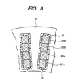
- Fig. 3 is a cross-sectional view showing the condition of conductor segments accommodated in each slot.
- an automotive alternator 1 includes a rotor 2, a stator 3, a housing 4, a rectifier 5, an output terminal 6, a rotary shaft 7, a brush 8, and a slip ring 9.
- the stator coil 3 includes a stator coil 31 and a stator core 32.
- the stator core 32 is fixed on an inner cylindrical wall of the housing 4.
- the stator coil 31 is wound in each slot of the stator core 32.
- the rotor 2 includes a Lundel-type rotor core 71 and a field coil 72.
- the Lundel-type rotor core 71 is fixed to the rotary shaft 7.
- the rotary shaft 7 is rotatably supported in the housing 4 which is stationary.
- the field coil 72 is wound around the rotor core 71.
- the rotor 2 is disposed radially inside the stator 3.
- the stator coil 31 is a three-phase armature winding which produces three-phase alternating-current voltages from its three alternating-current output terminals.
- the field coil 72 is magnetized when it receives a field current supplied via the brush 8 and the slip ring 9.
- the magnetized field coil 72 generates a magnetic field.
- the field current supplied to the field coil 72 is generally adjusted by a regulator (not known) so as to maintain the generator voltage at a predetermined level.
- This kind of automotive alternator is conventionally well known in its structure and its operations. Therefore, no further detailed explanation for it will be necessary.
- the stator coil 31 is constituted by a predetermined number of conductor segments 33 shown in Fig. 2.
- Each conductor segment 33 inserted into a slot of the stator core 32 from one side, extends in the slot and protrudes out of the stator core 32 from the other side.
- the protruding portion of the conductor segment 33 having a predetermined length, is twisted in the circumferential direction by an amount equivalent to an electric angle of ⁇ /2.
- the protruding portions of conductor segments 33 are welded at their distal ends according to predetermined combinations or pairings.
- Each conductor segment 33 has an elongated plate body configured as a whole into U shape which is sheath by a resin film except for the distal ends of the protruding portions, i.e., except for the distal end portions to be welded.
- This kind of stator coil itself, as characterized by sequentially connected conductor segments, is well known, too.
- conductor segment 33 The detailed arrangement of conductor segment 33 is explained hereinafter.
- the conductor segment 33 consists of a pentagonal head conductor portion, a pair of in-slot conductor portions, and a pair of protruding tail conductor portions.
- the in-slot conductor portions extend straight and parallel to each other from bifurcated ends (i.e., bend points) of the pentagonal head conductor portion.
- the protruding tail conductor portions extend outward from the corresponding in-slot conductor portions.
- the stator coil 31 consists of a first coil end portion (i.e., a head side coil end) 311, a second coil end portion (i.e., an tail side coil end) 312, and the in-slot conductor portions.
- the first coil end portion 311, formed as a whole into a ring shape, is disposed at one side of the stator core 32.
- the second coil end portion 312, formed as a whole into a ring shape, is disposed at the other side of the stator core 32.
- the in-slot conductor portions are disposed in the slots of the stator core 32. Namely, the first coil end portion 311 is constituted by the head conductor portions of the conductor segments 33, while the second coil end portion 312 is constituted by the protruding tail conductor portions of the conductor segments 33.
- the conductor segment 33 includes a large (turning) conductor segment 331 having a large turning head conductor portion and a small (turning) conductor segment 332 having a small turning head conductor portion.
- the large turning conductor segment 331 consists of a head conductor portion 331c, a pair of in-slot conductor portions 331a and 331b, and a pair of protruding tail conductor portions 331f and 331g.
- the in-slot conductor portions 331a and 331b extend straight in parallel with each other and are continuous from both ends of the head conductor portion 331c.
- the boundary between the head conductor portion 331c and each in-slot conductor portion 331a or 331b is a bend point 331h.
- the protruding tail conductor portions 331f and 331g are continuous from the corresponding in-slot conductor portions 331a and 331b and have distal ends 331d and 331e which are portions to be welded.
- the distal ends 331d and 331e can be also referred to as joint portions.
- the in-slot conductor portion 331a is positioned in the innermost layer.
- the in-slot conductor portion 331b is positioned in the outermost layer.
- the small turning conductor segment 332 consists of a head conductor portion 332c, a pair of in-slot conductor portions 332a and 332b, and a pair of tail conductor portions 332f and 332g.
- the in-slot conductor portions 332a and 332b extend straight in parallel with each other and are continuous from both ends of the head conductor portion 332c.
- the boundary between the head conductor portion 332c and each in-slot conductor portion 332a or 332b is a bend point 332h.
- the tail conductor portions 332f and 332g are continuous from the corresponding in-slot conductor portions 332a and 332b and have distal ends 332d and 332e which are portions to be welded.
- the distal ends 332d and 332e can be also referred to as joint portions.
- the in-slot conductor portion 332a is positioned in the inner middle layer.
- the in-slot conductor portion 332b is positioned in the outer middle layer.
- the in-slot conductor portion 331a of the innermost layer and the in-slot conductor portion 332a of the inner middle layer are accommodated in a predetermined slot of the stator core 32.
- the head conductor portion 331c of the large turning conductor segment 331 surrounds the head conductor portion 332c of the small turning conductor segment 332 in the condition where the conductor segments 331 and 332 are disposed in the slots of stator core 32.
- Fig. 3 shows the layout of the conductor segments accommodated in the slots of stator core 32.
- the in-slot conductor portion 331a of the innermost layer is disposed at a radially innermost end of the slot 35 of stator core 32. Disposed radially outer side with respect to the in-slot conductor portion 331a are successively, in this order, the in-slot conductor portion 332a of the inner middle layer, the in-slot conductor portion 332b' of the outer middle layer, and the in-slot conductor portion 331b' of the outermost layer.
- each slot 35 accommodates a total of four in-slot conductor portions of four layers aligned in the radial direction.
- the in-slot conductor portion 332b' belongs to a small turning conductor segment 332 which differs from the small turning conductor segment 332 having the in-slot conductor portion 332a.
- the in-slot conductor portion 331b' belongs to a large turning conductor segment 331 which differs from the large turning conductor segment 331 having the in-slot conductor portion 331a.
- Fig. 4 shows how the large turning conductor segment 331 and the small turning conductor segment 332 which are inserted into the slots 35.
- Head portion twisting process i.e., U-shaped segment forming process
- a required number of conductor segments each having a pine-needle shape, are prepared.
- Each prepared conductor segment has two elongated legs neighboring to each other and extending straight from its head being sharply bent.
- each pine-needle conductor segment is configured into a U-shaped conductor segment with a pair of in-slot conductor portions angularly spaced by one pole pitch in the circumferential direction.
- the U-shaped conductor segments are spatially disposed (more specifically, aligned in the circumferential direction) so that a required number of conductor segments are simultaneously inserted into each slot of the stator core.
- a pair of coaxial rings having insertion holes for example, disclosed in Fig.
- each pine-needle conductor segment is configured into a V-shaped conductor segment with a head portion straddling so as to form, as a whole, a V shape in the circumferential direction.
- the process of twisting the head conductor portion of a small turning conductor segment of a pine-needle shape is performed by using an inner middle layer ring and an outer middle layer ring which are coaxial with each other and rotatable in the circumferential direction to cause an angular shift between them.
- the inner middle layer ring has a radius corresponding to a radial position of the in-slot conductor portion of the inner middle layer.
- the inner middle layer ring has a predetermined number of insertion holes angularly arranged so as to correspond to respective in-slot conductor portions of the inner middle layer.
- the outer middle layer ring has a radius corresponding to a radial position of the in-slot conductor portion of the outer middle layer.
- the outer middle layer ring has a predetermined number of insertion holes angularly arranged so as to correspond to respective in-slot conductor portions of the outer middle layer.
- each small turning conductor segment of a pine-needle shape is performed in the following manner. First, the in-slot conductor portions of the inner middle layer are inserted into insertion holes of the inner middle layer ring. Then, the in-slot conductor portions of the outer middle layer are inserted into insertion holes of the outer middle layer ring. Next, the head portions of respective small turning conductor segments are fixed together with a holding plate to prevent them from rotating. Then, the inner middle layer ring and the outer middle layer ring are respectively rotated oppositely by a half pole pitch in the circumferential direction so as to cause an angular shift between them equivalent to one pole pitch. Through this twisting process, the small U-shaped turning conductor segment 332 is obtained as shown in Fig. 2.
- the holding plate relocates in the axial direction as the apex of the head portion of each small turning conductor segment moves toward the side flat surfaces of the coaxial rings in accordance with deformation of the head portion when configured into the U shape from its original pine-needle shape.
- the process of twisting the head conductor portion of a large turning conductor segment of a pine-needle shape is performed by using an innermost layer ring and an outermost layer ring which are coaxial with each other and rotatable in the circumferential direction to cause an angular shift between them.
- the innermost layer ring has a radius corresponding to a radial position of the in-slot conductor portion of the innermost layer.
- the innermost layer ring has a predetermined number of insertion holes angularly arranged so as to correspond to respective in-slot conductor portions of the innermost layer.
- the outermost layer ring has a radius corresponding to a radial position of the in-slot conductor portion of the outermost layer.
- the outermost layer ring has a predetermined number of insertion holes angularly arranged so as to correspond to respective in-slot conductor portions of the outermost layer.
- each large turning conductor segment of a pine-needle shape is performed in the following manner. First, the in-slot conductor portions of the innermost layer are inserted into insertion holes of the innermost layer ring. Then, the in-slot conductor portions of the outermost layer are inserted into insertion holes of the outermost layer ring. Next, the head portions of respective large turning conductor segments are fixed together with a holding plate to prevent them from rotating. Then, the innermost layer ring and the outermost layer ring are respectively rotated oppositely by a half pole pitch in the circumferential direction so as to cause an angular shift between them equivalent to one pole pitch. Through this twisting process, the large U-shaped turning conductor segment 331 is obtained as shown in Fig. 2.
- the holding plate relocates in the axial direction as the apex of the head portion of each large turning conductor segment moves toward the side flat surfaces of the coaxial rings in accordance with deformation of the head portion when configured into the U shape from its original pine-needle shape.
- the small U-shaped turning conductor segments 332 are pulled out of the insertion holes of the above-described rings.
- the small U-shaped turning conductor segments 332 are installed into the slots 35 of stator core 32 so as to straddle between a position corresponding to the inner middle layer and a position corresponding to the outer middle layer.
- the small U-shaped turning conductor segments 332 are assembled together with the above-described holding plate so that the small U-shaped turning conductor segments 332 can be installed into corresponding slots 35 at a time.
- the holding plate is removed.
- the large U-shaped turning conductor segments 331 are pulled out of the insertion holes of the above-described rings. As representatively shown in Fig. 4, the large U-shaped turning conductor segments 331 are installed into the slots 35 of stator core 32 so as to straddle between a position corresponding to the innermost layer and a position corresponding to the outermost layer. In this case, the large U-shaped turning conductor segments 331 are assembled together with the above-described holding plate so that the large U-shaped turning conductor segments 331 can be installed into corresponding slots 35 at a time. After accomplishing installation of the large U-shaped turning conductor segments 331 into the slots 35 of stator core 32, the holding plate is removed.
- the process for installing the large U-shaped turning conductor segments 331 and the small U-shaped turning conductor segments 332 into the slots 35 is not limited to the above-described one, and therefore can be variously changed.
- the insertion depth of the conductor segments 331 and 332 is regulated in the following manner.
- protruding distal end portions 350 of each conductor segment 331 or 332 are restricted so as to protrude by a predetermined length from an end surface 3200 of the stator core 32.
- the protruding distal end portions 350 of the conductor segment 331 correspond to the protruding tail conductor portions 331f and 331g shown in Fig. 2.
- the protruding distal end portions 350 of the conductor segment 332 correspond to the protruding tail conductor portions 332f and 332g shown in Fig. 2.
- Regulating the axial length of the protruding distal end portions 350 can be easily realized by using a stopper plate 400 which surely prevents the protruding distal end portions 350 from excessively protruding beyond the predetermined length.
- the straight portions 3320 are parallel to each other and extend straight in the axial direction form bend points 3330 (i.e., the boundary between the V-angled portion 3310 and each straight portion 3320).
- the straight portions 3320 are further continuous with respective in-slot conductor portions 331a and 331b disposed in the slots 35.
- the straight portions 3320 are in a line with the in-slot conductor portions 331a and 331b.
- the V-angled portion 3310 and a pair of straight portions 3320 cooperatively constitute a head conductor portion of the U-shaped conductor segment 331 which serves as a head side coil end (although the conductor segment 332 is omitted in the drawing).
- the small U-shaped turning conductor segment 332 the same result is obtained.
- the stopper plate 400 is used to regulate the length of the protruding distal end portions 350 protruding from the stator core 32, thereby securing the straight portions 3320.
- the large turning conductor segment 331 includes the outermost layer in-slot conductor portion 331b and the tail conductor portion 331g.
- the tail conductor portion 331g (which may be referred to as an outer layer side end portion), connected to the outermost layer in-slot conductor portion 331b, is twisted in a predetermined circumferential direction.
- the large turning conductor segment 331 includes the innermost layer in-slot conductor portion 331a and the tail conductor portion 331f.
- the tail conductor portion 331f (which may be referred to as an inner layer side end portion), connected to the innermost layer in-slot conductor portion 331a, is twisted in the opposite circumferential direction.
- the small turning conductor segment 332 includes the inner middle layer in-slot conductor portion 332a and the tail conductor portion 332f.
- the tail conductor portion 332f (which may be referred to as an inner layer side end portion), connected to the inner middle layer in-slot conductor portion 332a, is twisted in the predetermined circumferential direction.
- the small turning conductor segment 331 includes the outer middle layer in-slot conductor portion 332b and the tail conductor portion 332g.
- the tail conductor portion 332g (which may be referred to as an outer layer side end portion), connected to the outer middle layer in-slot conductor portion 332b, is twisted in the opposite circumferential direction.
- a sum of the circumferential twist amount of the tail conductor portion 331f and the circumferential twist amount of the tail conductor portion 332f is equivalent to one pole pitch.
- a sum of the circumferential twist amount of the tail conductor portion 331g and the circumferential twist amount of the tail conductor portion 332g is equivalent to one pole pitch.
- Fig. 6 is a vertical cross-sectional view schematically showing a stator coil twisting apparatus 500.
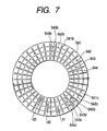
- Fig. 7 is a cross-sectional view taken along a line A-A of Fig. 6.
- the stator coil twisting apparatus 500 includes a work receiver 51 for receiving an outer peripheral portion of the stator core 32, a clamper 52 for regulating the movement of stator core 32 in the radial direction and for holding the stator core 32, a work presser 53 for preventing the stator core 32 from raising upward, a twist shaping unit 54 for twisting the legs of the segment 33 protruding from one end of the stator core 32, an elevating shaft 54a for shifting the twist shaping unit 54 in the axial direction, a plurality of rotary driving mechanisms 541a to 544a for rotating the twist shaping unit 54 in the circumferential direction, an axial driving mechanism 54b for shifting the elevating shaft 54a in the axial direction, and a controller 55 for controlling each of the rotary driving mechanisms 541a to 544a and the axial driving mechanism 54b.
- the twist shaping unit 54 includes a total of four cylindrical twisting jigs 541 to 544 which are coaxially disposed, with their top end surfaces being arranged at the same height.
- the rotary driving mechanisms 541a to 544a independently rotate the corresponding cylindrical twisting jigs 541 to 544.
- the axial driving mechanism 54b shifts the elevating shaft 54a in the up-and-down direction so that all of the cylindrical twisting jigs 541 to 544 can be integrally raised or lowered.
- the twisting jigs 541 to 544 have conductor segment insertion holes 541b to 544b, on their top end surfaces, for receiving the distal ends (i.e., joint portions) of the tail conductor portions 331f, 331g, 332f, and 332g of the conductor segment 33 inserted into the slots of the stator core 32.
- the number of conductor segment insertion holes 541b to 544b is equal to the number of the slots 35 of stator core 32 (refer to Figs. 3 and 4).
- the conductor segment insertion holes 541b to 544b are angularly spaced in the circumferential direction at predetermined intervals so as to correspond to the slots 35 of stator core 32.
- a reference numeral 34 represents an insulating resin sheet.
- the conductor segment insertion holes 541b to 544b are provided with partition walls 541c to 544c, 542d, and 543d for preventing the conductor segment insertion holes 541b to 544b which are adjacent to each other in the radial direction from communicating with each other.
- the thickness of respective partition walls 541c to 544c, 542d, and 543d is determined in the following manner.
- the neighboring partition walls 541c and 542c cooperatively form a gap d1 at the boundary between the outermost layer and the outer middle layer.
- the neighboring partition walls 542d and 543d cooperatively form a gap d2 at the boundary between the outer middle layer and the inner middle layer.
- the neighboring partition walls 543c and 544c cooperatively form a gap d3 at the boundary between the inner middle layer and the innermost layer.
- the gap d2 is set to be larger than the gap d1 or the gap d3.
- the stator coil twisting apparatus 500 functions in the following manner.
- stator core 32 With the conductor segments 33 disposed in its slots 35, is placed on the work receiver 51. Next, the outer cylindrical wall of the stator core 32 is fixed with the clamper 52. Thereafter, the work presser 53 depresses the upper portion of the stator core 32 as well as the head conductor portions 331c of the large turning conductor segments 331. Thus, the stator core 32 and the conductor segments 33 are surely fixed so as not to move in the up-and-down direction.
- the elevating shaft 54a raises the twist shaping unit 54 so that the tail conductor portions 331f, 331g, 332f, and 332g of respective conductor segments 33 are inserted into the conductor segment insertion holes 541b to 544b formed in respective twisting jigs 541 to 544.
- the conductor segment insertion holes 541b to 544b can receive only the distal ends (which later become the joint portions) of tail conductor portions 331f, 331g, 332f, and 332g of respective conductor segments 33.
- tail conductor portions 331f, 331g, 332f, and 332g of respective conductor segments 33 are tapered, they can be smoothly inserted into the conductor segment insertion holes 541b to 544b.
- twist shaping unit 54 After the tail conductor portions 331f, 331g, 332f, and 332g of respective conductor segments 33 are inserted into the conductor segment insertion holes 541b to 544b of the twist shaping unit 54, the twist shaping unit 54 is rotated by the rotary driving mechanisms 541a to 544a and raised or lowered by the axial driving mechanism 54b. The twist shaping unit 54 performs this operation for all of the twisting jigs 541 to 544 simultaneously.
- twisting jigs 541 and 543 are rotated in the clockwise direction by a first angle, while the twisting jigs 542 and 544 are rotated in the counterclockwise direction by a second angle.
- the first angle is set to be larger than the second angle by an amount of 50% or more.
- the bending radius is put to elongated portions (except for the joint portions) of the tail conductor portions 331f, 331g, 332f, and 332g of respective conductor segments 33 extending from the outlet of the slots 35 to the inlet of the conductor segment insertion holes 541b to 544b. Accordingly, a large bending radius is put to the tail conductor portions 331g and 332f while a small bending radius is put to the tail conductor portions 331f and 332g.
- the twist shaping unit 54 is rotated by the rotary driving mechanisms 541a to 544a and raised by the axial driving mechanism 54b so that the elongated portions of the tail conductor portions 331f, 331g, 332f, and 332g of respective conductor segments 33 extending from the outlet of the slots 35 to the inlet of the conductor segment insertion holes 541b to 544b are maintained to have a constant length.
- the tail conductor portions 331f, 331g, 332f, and 332g of respective conductor segments 33 rotate and rise so as to trace an arc locus.
- the operation for twisting the tail conductor portions so as to trace an arc locus is performed until the angle exceeds a regulation angle equivalent to a half pole pitch (T/2) by a predetermined amount.
- this twisting process includes an axial shifting of the twisting jigs 541 to 544 which is performed so as to exceed a regulation distance by a predetermined amount. As each conductor segment 33 is already bent at the outlet portion of the slot 35, the conductor segment 33 is not pulled out of the slot 35 when the conductor segment 33 rises.
- the axial driving mechanism 54b and the rotary driving mechanisms 541a to 544a are controlled to rotate the twist shaping unit 54 in the opposite direction and lower it.
- the twist shaping unit 54 is further lowered to remove the tail conductor portions 331f, 331g, 332f, and 332g of respective conductor segments 33 out of the conductor segment insertion holes 541b to 544b of the twisting jigs 541 to 544.
- the rotary driving mechanisms 541a to 544a rotate the twist shaping unit 54 to return it to the original position.
- the clamper 52 and the work presser 53 are released from the stator core 32. Then, the stator with the twisted conductor segments 33 is taken out.
- the above-described twisting process is characterized by first deforming the tail conductor portions of each conductor segment 33 in only the circumferential direction to make the conductor segment 33 incline in the circumferential direction, then deforming the tail conductor portions of each conductor segment 33 in both the circumferential direction and the axial direction to make the conductor segment 33 incline deeply, and thereafter excessively deforming the tail conductor portions of each conductor segment 33 in both the circumferential direction and the axial direction beyond the regulation values to make the conductor segment 33 incline excessively, and finally letting the tail conductor portions of each conductor segment 33 return to the regulation values due to self spring back deformation.
- the twist shaping unit 54 causes the shift movement relative to the stator core 32 not only the circumferential direction but also in the axial direction. Hence, it becomes possible to twist the tail conductor portions 331f, 331g, 332f, and 332g of conductor segments 33 so as to trace an arc locus, according to which the length of the tail conductor portions 331f, 331g, 332f, and 332g except for the joint portions 331d, 331e, 332d, and 332e can be kept to a constant value.
- the elongated portions of the tail conductor portions 331f, 331g, 332f, and 332g of respective conductor segments 33 extending from the outlet of the slots 35 to the inlet of the conductor segment insertion holes 541b to 544b can be maintained to a constant length. As a result, it becomes possible to prevent the conductor segments 33 from being pulled out of the conductor segment insertion holes 541b to 544b.
- joint portions 331d, 331e, 332d, and 332e of the conductor segments 33 are inserted into the conductor segment insertion holes 541b to 544b. As described above, this prevents the conductor segments 33 from being pulled out of the conductor segment insertion holes 541b to 544b. Accordingly, it becomes possible to prevent the portions of the conductor segments 33 except for the joint portions 331d, 331e, 332d, and 332e from being damaged or wounded.
- the joint portions 331d, 331e, 332d, and 332e are free from damage or wound because they are, after being twisted, welded with adjacent joint portions of other conductor segments.
- the gap defined by the partition walls 542d and 543d at the boundary between the outer middle layer and the inner middle layer is set to be larger than the gap defined by the partition walls 541c and 542c at the boundary between the outermost layer and the outer middle layer or the gap defined by the partition walls 543c and 544c at the boundary between the inner middle layer and the innermost layer.
- the outermost layer and the outer middle layer are rotated in the opposite directions so as to cause a mutual displacement equivalent to a half pole pitch.
- the innermost layer and the inner middle layer are rotated in the opposite directions so as to cause a mutual displacement equivalent to a half pole pitch.
- the conductor segments of the outermost layer and the outer middle layer approach to each other, while the conductor segments of the innermost layer and the inner middle layer approach to each other.
- the gap between the partition walls 542d and 543d at the boundary between the outer middle layer and the inner middle layer is set to be large.
- the clearance between the conductor segment 33 of the outer middle layer and the conductor segment 33 of the inner middle layer is relatively large.
- the clearance between two conductor segments 33 to be welded each other becomes small.
- the clearance between the conductor segment 33 of the outermost layer and the conductor segment 33 of the outer middle layer becomes relatively small.
- the clearance between the conductor segment 33 of the innermost layer and the conductor segment 33 of the inner middle layer becomes relatively small.
- the clearance between the conductor segments 33 not welded each other is maintained to a relatively large value. This is effective to facilitate the welding process.
- the twisting jigs 541, 542, 543, and 544 are exchangeable so as to fit to any type of stator.
- the slot number of the stator is not limited to 36 slots.
- the twist shaping unit 54 is applicable to any type of a stator whose slot number may be 48, 84, 96, or others. It is possible to independently control the rotational amount of the twisting jigs 541, 542, 543, and 544.
- the axial shift amount of the twist shaping unit 54 is controlled independent of the rotational amount of the twisting jigs 541, 542, 543, and 544.
- the twist shaping unit 54 of this embodiment is applicable to various types of stators for performing the twist process appropriately.
- the conductor segment 33 of the innermost layer and the conductor segment 33 of the inner middle layer are welded at their distal ends (i.e., the joint portions) as shown in Fig. 2.
- the conductor segment 33 of the outermost layer and the conductor segment 33 of the outer middle layer are welded at their distal ends (i.e., the joint portions).
- the stator coil 31 is thus accomplished.
- the practical welding used in this embodiment is, for example, TIG welding, brazing, electron-beam welding, laser welding, or the like.
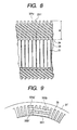
- Figs. 8 and 9 show the stator coil 31 being thus accomplished.
- the tail conductor portions 331f and 332g are largely twisted (or inclined) in the circumferential direction compared with the tail conductor portions 331g and 332f.
- the preferred embodiment of the present invention provides a coil for an electric rotary machine including a plurality of conductor segments (33) each having a V-shaped head conductor portion (331c, 332c), a pair of in-slot conductor portions (331a, 331b, 332a, 332b) extending from both ends of the head conductor portion and accommodated in two different slots (35) of a core (32), and a pair of tail conductor portions (331f, 331g, 332f, 332g) continuing from the in-slot conductor portions and protruding out of axially opposite openings of the slots and extending at least in a circumferential direction.
- the conductor segments (33) are successively connected by joining distal ends (331d, 331e 332d, 332e) of the tail conductor portions.
- the head conductor portion of each conductor segment constitutes part of a head side coil end (311, 600) of the coil (31).
- the tail conductor portion of each conductor segment constitutes part of a tail side coil end (312) of the coil (31).
- the head conductor portion or the tail conductor portion includes a V-angled portion (3310) and straight portions (3320).
- the V-angled portion (3310) includes an apex positioned farthest in an axial direction from the core and slant portions extending from the apex in both circumferential directions so as to gradually approach to an end surface of the core.
- Each of the straight portions (3320) is bent from an end of the V-angled portion so as to extend straight in a line with the in-line conductor portion (331a, 331b). And, an axial length of each the straight portions (3320) is longer than an axial length of the V-angled portion (3310).
- the preferred embodiment of the present invention provides a method for manufacturing the coil for an electric rotary machine, including a conductor segment inserting process, a conductor segment returning process, a tail conductor portion twisting process, and a joining process.
- the conductor segment inserting process is for inserting each conductor segment (33) into a slot (35) of the core (32) in the axial direction until a bend point (3331h, 332h, 3330) between the V-angled portion (3310) and each straight portion (3320) reaches an axially near-side opening (35a) of the slot (35), while allowing each tail conductor portion (331f, 331g, 332f, 332g) to protrude out of the core from an axially far-side opening (35b) of the slot.
- the conductor segment returning process is for returning the conductor segment (33) back in the axial direction by a predetermined length (L2) to form the head side coil end (311, 600).
- the tail conductor portion twisting process is for twisting each tail conductor portion in the circumferential direction by a predetermined angle.
- the joining process is for joining the distal ends (331d, 331e 332d, 332e) of the tail conductor portions according to predetermined pairings.
- the large U-shaped turning conductor segment 331 constitutes a head side coil end 600 of stator coil 31.
- the large U-shaped turning conductor segment 331 has the head conductor portion consisting of the V-angled portion 3310 and a pair of straight portions 3320.
- Each straight portion 3320 extends out of the slot 35 from an axially near-side opening 35a and aligned in a line with the in-slot conductor portion 331a or 331b.
- the protruding distal end portions 350 protrudes from an axially far-side opening 35b of the slot 35.
- the small U-shaped turning conductor segment 332 has the head conductor portion consisting of a V-angled portion and a pair of straight portions.
- the boundary (i.e., bend point 3330) between the V-angled portion 3310 and each straight portion 3320 is spaced sufficiently far from the sharp edge of the axially near-side opening 35a of slot 35. This effective prevents the resin film covering the surface of the conductor segment 33 from being pressed hardly to the sharp edge of the opening periphery of the slot. Thus, it becomes possible to satisfactorily maintain the insulation property of the resin film of the conductor segment.
- cooling air can smoothly flow in radial directions via the clearances between the slots arrayed at predetermined angular intervals in the circumferential direction without being blocked by the conductor segments.
- the clearances between the slots are portions which are next to so-called teeth of the stator core in the axial direction.
- cooling performance of the stator core is improved.
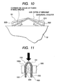
- the head conductor portion of the conductor segment is configured into a pentagonal shape. As comparatively shown in Fig. 10, the total length of the head conductor portion is longer than that of a conventional triangular one under the condition that the axial protruding length of the head conductor portion is the same. The total surface of the head conductor portion to be exposed to the cooling air is increased. This is effective to improve the cooling performance of the head side coil end.
- an axially protruding distance of the straight portion 3320 is longer than that of the V-angled portion 3310 so as to enhance the above-described effects.
- each in-slot conductor portion is made of a flat type of a rectangular wire. At least one side surface of the in-slot conductor portion is entirely brought into face-to-face contact with the flat inner surface of the slot via an insulator.
- the straight portion of the V-shaped head conductor portion integrally extends from the in-slot conductor portion so as to constitute one coil end.
- the straight portion of the V-shaped head conductor portion extends straight in a line with the in-slot conductor portion beyond the slot opening by a predetermined distance.
- the protruding length of each head conductor portion i.e., apex of the head portion
- the protruding length of each head conductor portion is set to be the same value.
- This arrangement is advantageous in that, when seen on a projection surface perpendicular to the radial direction, most of the conductors overlap each other. The air flow loss is greatly reduced. Hence, when the forced cooling air flowing in radial directions is applied to the head side coil end or to the tail side coil end, the fluid resistance is small.
- the axial length of the straight portion of the head conductor portion is set to be smaller than that of the V-angled portion of the head conductor portion. It is, however, preferable to set the axial length of the straight portion to be larger than that of the V-angled portion.
- the stator coil is formed by welding the distal ends of the conductor segments, each having a head portion being configured beforehand into V shape (hereinafter, referred to as V-shaped conductor segment), at only one side of the stator core.
- V-shaped conductor segment V shape
- the above-described V-shaped conductor segments can be replaced with later-described oblique L-shaped conductor segments and I-shaped conductor segments to weld them at both sides of the stator core and finally obtain the V-shaped conductor segments of the present invention.
- the head conductor portion of each conductor segment consists of the V-angled portion and the straight portions.
- the bend point (i.e., boundary) between the V-angled portion and each straight portion is kept far from the sharp edge of the core defining the slot opening.
- a bend point between the straight portion and the partial V-angled portion is kept far from the sharp edge of the core defining the slot opening to obtain the same functions and effects with respect to the insulation properties.
- the tail conductor portions have similar straight portions so as to ensure the above-described functions and effects.
- the above-described embodiment is an example of the present invention applied to a stator coil wound around a stator core.
- the subject matter of the present invention resides in that the V-shaped conductor segment includes a V-angled portion and a pair of straight portions cooperative constituting a head portion and that the bend pont between the V-angled portion and each straight portion is kept far from the sharp edge of a stator core defining the slot opening.
- the subject matter of the present invention is also effected in a case where the V-shaped conductor segments are installed in slots of the rotor core.
- the present invention encompasses not only the above-described stator coil but also a rotor coil wound around a rotor core as long as the conductor segments of the rotor coil have a head conductor portion consisting of a V-shaped bend portion and a pair of straight portions and the bend point between the V-angled portion and each straight portion is kept far from the sharp edge of the rotor core defining the slot opening.
- the straight portions are provided at the head conductor portion of the conductor segments.
- the similar straight portions are provided at the tail conductor portion of the conductor segments which protrude the other side of the core.
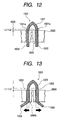
- Figs. 11 through 14 show the detailed process for installing a V-shaped conductor segment 1000 into slots of a stator core 2000.
- the V-shaped conductor segment 1000 includes a V-angled portion 1001 configured beforehand into V shape and a pair of straight legs 1002 extending straight from both ends (i.e., bend point 1001a) of the V-angled portion 1001 in parallel with each other.
- the straight legs 1002 of the V-shaped conductor segment 1000 are inserted into slots 3000 of the stator core 2000 in the axial direction from an axially near-side opening 3000a of the slot 3000 (as shown in Fig. 11).
- the insertion depth of the V-shaped conductor segment 1000 is set to a predetermined value so that each leg 1002 has a residual root portion 1003 protruding out of the axially near-side opening 3000a of the slot 3000 toward the V-angled portion 1001.
- the length of the residual root portion 1003 is regulated to a predetermined length L1+L2 (as shown in Fig. 12).
- the V-shaped conductor segment 1000 is fully inserted into slots 3000 in the axial direction and then is pulled back by a predetermined length L1.
- the V-shaped conductor segment 1000 is inserted into slots 3000 in the axial direction but stopped before it reaches the dead end so as to leave the residual root portion 1003 having the length of L1.
- each leg 1002 protruding from the slot 3000 toward the far side opposite to the V-angled portion 1001 is bent, at an axially far-side opening 3000b of the slot 3000, into a tilt portion 1004 by bending the leg 1002 in the circumferential direction (as well as, if necessary, in the radial direction) about the pivot on the side surface of the stator core 2000 (as shown in Fig. 13).
- the V-shaped conductor segment 1000 is depressed in the axial direction toward the tilt portions 1004 by the predetermined length L2 so as to leave straight portions 1005 continuing from both ends of the V-angled portion 1001 and extending in a line with the straight leg 1002 accommodated in the slot 3000 at one side of the stator core 2000 (i.e., at the axially near-side opening 3000a) and another straight portions 1006 continuing from respective tilt portions 1004 and extending in a line with the straight leg 1002 accommodated in the slot 3000 at the other side of the stator core 2000 (i.e., at the axially far-side opening 3000b).
- V-angled portion 1001 and the straight portions 1005 are collectively referred to as a head conductor portion 1007 or a V-shaped head portion.
- the tilt portion 1004 and the straight portion 1006, which are continuous with each other, are collectively referred to as a protruding tail conductor portion.
- each straight leg 1002 accommodated in the slot 3000 is referred to as in-slot conductor portion.
- the conductor segments have, at both side surfaces of the stator core 2000, the straight portions 1005 and 1006 protruding out of the slots and extending in the axial direction (as shown in Fig. 14).
- the insulating resin film covering the surface of V-shaped conductor segment 1000 from being damaged or wounded by the sharp edges of the stator core 2000 defining the slot openings 3000a and 3000b (opened in the axial direction).
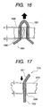
- Figs. 11,15 and 16 show a modified process for installing the V-shaped conductor segment 1000 into the slots of the stator core 2000.
- the legs of V-shaped conductor segment 1000 are inserted into the slots 3000 of stator core 2000 in the axial direction from one side of the stator core 2000 (as shown in Fig. 11).
- each leg 1002 protruding from the slot 3000 toward the far side opposite to the V-angled portion 1001 is bent, at the portion offset from the side surface of the stator core 2000 by the length of L1+L2, into the tilt portion 1004 (as shown in Fig. 15).
- the V-shaped conductor segment 1000 is pushed back in the axial direction toward the V-angled portion 1001 by the predetermined length L1 so as to leave the straight portions 1005 continuing from both ends of the V-angled portion 1001 and extending in a line with the straight leg 1002 accommodated in the slot 3000 at one side of the stator core 2000 (i.e., at the axially near-side opening 3000a) and the straight portions 1006 continuing from respective tilt portions 1004 and extending in a line with the straight leg 1002 accommodated in the slot 3000 at the other side of the stator core 2000 (i.e., at the axially far-side opening 3000b).
- the V-angled portion 1001 and the straight portions 1005 are collectively referred to as the head conductor portion 1007 or the V-shaped head portion.
- the tilt portion 1004 and the straight portion 1006, which are continuous with each other, are collectively referred to as the protruding tail conductor portion.
- each straight leg 1002 accommodated in the slot 3000 is referred to as the in-slot conductor portion.
- Figs. 17 and 18 show another modified process for installing the conductor segment into the slot of the stator core 2000.
- the protruding portions of the oblique L-shaped conductor segment 1010 are bent at both sides of the stator core 2000 so as to leave the straight portion 1005 and the straight portion 1006 which extend in a line with the straight leg accommodated in the slot 3000.
- the conductor segments are welded to form a V-shaped coil end similar to the above-described V-shaped conductor segment 1000.
- the oblique L-shaped conductor segment consists of a partial V-angled portion 1001' and the straight leg 1002.
- the partial V-angled portion 1001' is a half symmetrical cut of the V-angled portion 1001 shown in Fig. 14 which is divided at the apex thereof.
- the cutting portion of the L-shaped conductor segments 1010 is arbitrarily changed to other portion as long as the V-shaped conductor segment 1000 is obtained by welding the L-shaped conductor segments 1010.
- the oblique L-shaped conductor segment 1010 is inserted into the slot 3000 in the axial direction from one side of the stator core 2000 (as shown in Fig. 17).
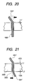
- Figs. 19 to 21 show another modified process for installing the conductor segment into the slot of the stator core 2000.
- the oblique L-shaped conductor segment 1010 is replaced with an I-shaped conductor segment 1020.
- the I-shaped conductor segment 1020 is configured into the above-described L-shaped conductor segment 1010 by bending one protruding portion of the I-shaped conductor segment 1020. Thereafter, the other protruding portion of the I-shaped conductor segment 1020 is bent. Then, a pair of oblique L-shaped conductor segments 1010 are welded at their upper ends to form the V-shaped conductor segment 1000.
- the preferred embodiment of the present invention provides a method for manufacturing an electric rotary machine including a winding and a core.
- the winding consists of a plurality of conductor segments (1000), each comprising a V-shaped head conductor portion (1001) and a pair of straight conductor portions (1002) extending from both ends of the V-shaped portion.
- the conductor segments are covered by an insulating film and successively joined at distal ends of the straight conductor portions.
- the core includes a plurality of slots (3000) arrayed at predetermined angular intervals in a circumferential direction for accommodating the conductor segments (1000).
- Each of the slots has an axially near-side opening (3000a) through which the straight conductor portion (1002) is inserted into the slot (3000) and an axially far-side opening (3000b) from which the distal end of the straight conductor portion protrudes.
- the V-shaped head conductor portion (1001) of each conductor segment is held at one side of the core where the axially near-side opening (3000a) is provided, and protruding portions (1004) of the straight conductor portions are held at the other side of the core where the axially far side opening (3000b) is provided.
- This manufacturing method includes an accommodating process, a twist shaping process, and a shifting process.
- the accommodating process is for accommodating the straight conductor portions (1002) of each conductor segment into different slots (3000) so that at least part of each straight conductor portion extends as an exposed straight portion (1005, 1006) out of the slot from either the axially near-side opening or the axially far-side opening by a predetermined length.
- the twist shaping process is for twisting the protruding portions (1004) of the straight conductor portions in the circumferential direction.
- the shifting process is for shifting the straight conductor portion (1002) into the slot (3000) from one of the axially near-side opening or the axially far-side opening so that at least part of the exposed straight portion (1005, 1006) is accommodated in the slot and is for allowing the straight conductor portion (1002) to protrude out of the slot as another exposed straight portion (1005, 1006) from the other of the axially near-side opening or the axially far-side opening.
Landscapes
- Engineering & Computer Science (AREA)
- Power Engineering (AREA)
- Manufacturing & Machinery (AREA)
- Manufacture Of Motors, Generators (AREA)
- Windings For Motors And Generators (AREA)
- Iron Core Of Rotating Electric Machines (AREA)
- Insulation, Fastening Of Motor, Generator Windings (AREA)
- Motor Or Generator Cooling System (AREA)
Applications Claiming Priority (4)
| Application Number | Priority Date | Filing Date | Title |
|---|---|---|---|
| JP2001394344 | 2001-12-26 | ||
| JP2001394344 | 2001-12-26 | ||
| JP2002125680 | 2002-04-26 | ||
| JP2002125680A JP3551378B2 (ja) | 2001-12-26 | 2002-04-26 | 回転電機のコイルおよびその製造方法 |
Publications (3)
| Publication Number | Publication Date |
|---|---|
| EP1324461A2 true EP1324461A2 (fr) | 2003-07-02 |
| EP1324461A3 EP1324461A3 (fr) | 2003-11-19 |
| EP1324461B1 EP1324461B1 (fr) | 2006-04-12 |
Family
ID=26625288
Family Applications (1)
| Application Number | Title | Priority Date | Filing Date |
|---|---|---|---|
| EP02028842A Expired - Lifetime EP1324461B1 (fr) | 2001-12-26 | 2002-12-23 | Bobinage pour machine électrique tournante, procédé de fabrication dudit bobinage, et procédé de fabrication d'une machine électrique tournante utilisant ledit bobinage |
Country Status (5)
| Country | Link |
|---|---|
| US (1) | US6862796B2 (fr) |
| EP (1) | EP1324461B1 (fr) |
| JP (1) | JP3551378B2 (fr) |
| KR (1) | KR100485904B1 (fr) |
| DE (1) | DE60210572T2 (fr) |
Cited By (7)
| Publication number | Priority date | Publication date | Assignee | Title |
|---|---|---|---|---|
| WO2007036578A1 (fr) * | 2005-09-30 | 2007-04-05 | Thales | Outillage de realisation de bobinages d'un stator d'une machine electrique et procede de realisation de bobinage |
| ITBO20100585A1 (it) * | 2010-09-29 | 2012-03-30 | Magneti Marelli Spa | Metodo di costruzione di una macchina elettrica presentante un avvolgimento statorico con barre rigide |
| WO2012093413A1 (fr) * | 2011-01-04 | 2012-07-12 | Tecnomatic S.P.A. | Procédé et dispositif destinés à torsader les extrémités de conducteurs, en particulier de bobinages de machines électriques |
| CN109067114A (zh) * | 2018-09-06 | 2018-12-21 | 成都中车电机有限公司 | 直流牵引电动机异槽电枢线圈的简易成型方法 |
| WO2018233774A1 (fr) * | 2017-06-20 | 2018-12-27 | Grob-Werke Gmbh & Co. Kg | Dispositif et procédé servant à fabriquer un élément de machine pourvu d'enroulements pour une machine électrique |
| WO2019161846A1 (fr) * | 2018-02-21 | 2019-08-29 | Grob-Werke Gmbh & Co. Kg | Dispositif et procédé pour modifier la forme de pièces dans la direction périphérique |
| WO2020069902A1 (fr) * | 2018-10-05 | 2020-04-09 | Bayerische Motoren Werke Aktiengesellschaft | Procédé de fabrication d'un moteur electrique et dispositif |
Families Citing this family (21)
| Publication number | Priority date | Publication date | Assignee | Title |
|---|---|---|---|---|
| TWM346978U (en) * | 2008-06-27 | 2008-12-11 | chao-xiong Lin | Triphase rotary electric power generator |
| JP5392548B2 (ja) * | 2009-04-07 | 2014-01-22 | 株式会社デンソー | ステータコイルのコイルエンド成形方法およびコイルエンド成形装置 |
| JPWO2011102150A1 (ja) * | 2010-02-18 | 2013-06-17 | アイシン・エィ・ダブリュ株式会社 | 回転電機用電機子 |
| IT1401829B1 (it) * | 2010-09-29 | 2013-08-28 | Magneti Marelli Spa | Macchina elettrica presentante un avvolgimento statorico con barre rigide e relativo metodo di costruzione |
| KR101398459B1 (ko) * | 2012-05-22 | 2014-05-27 | 엘지전자 주식회사 | 회전전기기계의 고정자 및 그의 제조방법 |
| JP5846081B2 (ja) * | 2012-08-30 | 2016-01-20 | トヨタ自動車株式会社 | 回転電機のステータコイル構造 |
| JP5942714B2 (ja) * | 2012-09-07 | 2016-06-29 | 株式会社デンソー | 回転電機 |
| JP5850878B2 (ja) * | 2013-05-16 | 2016-02-03 | 本田技研工業株式会社 | セグメントコンダクタ型の回転電機のステータ及びその製造方法 |
| JP5749772B2 (ja) * | 2013-09-18 | 2015-07-15 | 本田技研工業株式会社 | 挿入方法および挿入装置 |
| DE102014208082B4 (de) * | 2014-04-29 | 2019-03-07 | Continental Automotive Gmbh | Verfahren und Vorrichtung zum Herstellen einer Wicklung einer elektrischen Maschine |
| DE102014208077B4 (de) | 2014-04-29 | 2021-01-21 | Vitesco Technologies GmbH | Wicklungsträger und elektrische Maschine |
| JP6274118B2 (ja) * | 2015-01-13 | 2018-02-07 | トヨタ自動車株式会社 | ステータの絶縁処理装置 |
| DE102015217922A1 (de) * | 2015-09-18 | 2017-03-23 | Continental Automotive Gmbh | Verfahren und zweiteilige Werkzeuganordnung zum Herstellen eines Stators für eine elektrische Maschine |
| DE102015217936A1 (de) * | 2015-09-18 | 2017-03-23 | Continental Automotive Gmbh | Verfahren und einteilige Werkzeuganordnung zum Herstellen eines Stators für eine elektrische Maschine |
| JP6305471B2 (ja) * | 2016-07-25 | 2018-04-04 | 本田技研工業株式会社 | ステータの製造方法及びその装置 |
| TWI673944B (zh) * | 2017-03-24 | 2019-10-01 | 美商江森自控技術公司 | 用於冷卻器馬達的液體噴射噴嘴 |
| DE102017004538A1 (de) * | 2017-05-11 | 2018-11-15 | Gehring E-Tech Gmbh | Verfahren und Vorrichtung zum Umformen von U-förmigen elektrischen Leitern |
| KR102566022B1 (ko) * | 2018-02-23 | 2023-08-11 | 현대모비스 주식회사 | 헤어핀 권선모터 |
| JP7066466B2 (ja) * | 2018-03-22 | 2022-05-13 | 本田技研工業株式会社 | 捻り曲げ装置 |
| IT201800006494A1 (it) * | 2018-06-20 | 2019-12-20 | Apparato e metodo per il modellamento di hairpin | |
| KR20250090079A (ko) | 2023-12-12 | 2025-06-19 | 주식회사 엘지에너지솔루션 | 크림핑 가압부 위치 측정부가 부가된 원통형 전지의 크림핑 장치 |
Family Cites Families (16)
| Publication number | Priority date | Publication date | Assignee | Title |
|---|---|---|---|---|
| US624956A (en) * | 1899-05-16 | Metallic tubiws | ||
| JPS57197738A (en) | 1981-05-30 | 1982-12-04 | Toshiba Corp | Stroboscanning electron microscope |
| US5363546A (en) * | 1992-02-03 | 1994-11-15 | General Electric Company | Apparatus for making armatures for electrodynamic machines |
| JP3807089B2 (ja) * | 1997-05-26 | 2006-08-09 | 株式会社デンソー | 車両用交流発電機の固定子及びその分解方法 |
| US6124660A (en) * | 1997-05-26 | 2000-09-26 | Denso Corporation | AC generator for vehicles |
| JP3303773B2 (ja) * | 1997-05-26 | 2002-07-22 | 株式会社デンソー | 車両用交流発電機の固定子 |
| JPH1127888A (ja) | 1997-06-30 | 1999-01-29 | Hitachi Ltd | 回転電機の固定子及び固定子コイル挿入装置 |
| ES2203986T5 (es) | 1997-10-16 | 2007-12-01 | Denso Corporation | Metodo y aparato para arrollar las partes de vuelta de segmentos conductores de estator en u. |
| JP3903609B2 (ja) | 1998-08-24 | 2007-04-11 | 株式会社デンソー | 回転電機の波巻きコイルおよびその製造方法 |
| JP3196738B2 (ja) | 1998-09-11 | 2001-08-06 | 株式会社デンソー | ステータ製造装置及びステータ製造方法 |
| JP3201397B2 (ja) * | 1999-03-30 | 2001-08-20 | 株式会社デンソー | 回転電機の製造方法 |
| JP4042250B2 (ja) | 1999-04-05 | 2008-02-06 | 株式会社デンソー | 車両用交流発電機 |
| JP2001069731A (ja) * | 1999-08-31 | 2001-03-16 | Denso Corp | 回転電機の巻線製造方法 |
| JP3589134B2 (ja) * | 2000-01-12 | 2004-11-17 | 株式会社デンソー | ステータ製造方法及びその装置 |
| JP2001275283A (ja) * | 2000-03-28 | 2001-10-05 | Mitsubishi Electric Corp | 車両用交流発電機の固定子 |
| JP3894411B2 (ja) | 2000-04-13 | 2007-03-22 | 三菱電機株式会社 | 車両用交流発電機 |
-
2002
- 2002-04-26 JP JP2002125680A patent/JP3551378B2/ja not_active Expired - Lifetime
- 2002-12-23 EP EP02028842A patent/EP1324461B1/fr not_active Expired - Lifetime
- 2002-12-23 DE DE60210572T patent/DE60210572T2/de not_active Expired - Lifetime
- 2002-12-26 US US10/328,148 patent/US6862796B2/en not_active Expired - Lifetime
- 2002-12-26 KR KR10-2002-0084452A patent/KR100485904B1/ko not_active Expired - Lifetime
Cited By (16)
| Publication number | Priority date | Publication date | Assignee | Title |
|---|---|---|---|---|
| WO2007036578A1 (fr) * | 2005-09-30 | 2007-04-05 | Thales | Outillage de realisation de bobinages d'un stator d'une machine electrique et procede de realisation de bobinage |
| FR2891673A1 (fr) * | 2005-09-30 | 2007-04-06 | Thales Sa | Outillage de realisation de bobinages d'un stator d'une machine electrique et procede de realisation de bobinage. |
| ITBO20100585A1 (it) * | 2010-09-29 | 2012-03-30 | Magneti Marelli Spa | Metodo di costruzione di una macchina elettrica presentante un avvolgimento statorico con barre rigide |
| EA024602B1 (ru) * | 2011-01-04 | 2016-10-31 | Текноматик С.П.А. | Способ и приспособление для гибки концевых участков стержневых проводников, в частности для стержневых обмоток электрических машин |
| CN103314508A (zh) * | 2011-01-04 | 2013-09-18 | 泰克马奇有限公司 | 用于缠绕特别是用于电机条形绕组的导条端部的方法和固定装置 |
| JP2014501485A (ja) * | 2011-01-04 | 2014-01-20 | テクノマティック・ソシエタ・ペル・アチオニ | 特に電気機械の棒巻線のための棒導体の両端部の捩り方法および治具 |
| US8826513B2 (en) | 2011-01-04 | 2014-09-09 | Technomatic S.p.A. | Method for twisting end portions of bar conductors, in particular for bar windings of electric machines |
| CN103314508B (zh) * | 2011-01-04 | 2016-02-17 | 泰克马奇有限公司 | 用于电机条形绕组的导条端部的缠绕方法和固定装置 |
| WO2012093413A1 (fr) * | 2011-01-04 | 2012-07-12 | Tecnomatic S.P.A. | Procédé et dispositif destinés à torsader les extrémités de conducteurs, en particulier de bobinages de machines électriques |
| US9520762B2 (en) | 2011-01-04 | 2016-12-13 | Tecnomatic S.P.A. | Method and fixture for twisting end portions of bar conductors, in particular for bar windings of electric machines |
| WO2018233774A1 (fr) * | 2017-06-20 | 2018-12-27 | Grob-Werke Gmbh & Co. Kg | Dispositif et procédé servant à fabriquer un élément de machine pourvu d'enroulements pour une machine électrique |
| WO2019161846A1 (fr) * | 2018-02-21 | 2019-08-29 | Grob-Werke Gmbh & Co. Kg | Dispositif et procédé pour modifier la forme de pièces dans la direction périphérique |
| US11462976B2 (en) | 2018-02-21 | 2022-10-04 | Grob-Werke Gmbh & Co. Kg | Device and method for shaping wire ends in a circumferential direction |
| CN109067114A (zh) * | 2018-09-06 | 2018-12-21 | 成都中车电机有限公司 | 直流牵引电动机异槽电枢线圈的简易成型方法 |
| WO2020069902A1 (fr) * | 2018-10-05 | 2020-04-09 | Bayerische Motoren Werke Aktiengesellschaft | Procédé de fabrication d'un moteur electrique et dispositif |
| US11901778B2 (en) | 2018-10-05 | 2024-02-13 | Bayerische Motoren Werke Aktiengesellschaft | Method for producing an electric motor, and apparatus |
Also Published As
| Publication number | Publication date |
|---|---|
| JP3551378B2 (ja) | 2004-08-04 |
| DE60210572T2 (de) | 2007-03-15 |
| JP2003259585A (ja) | 2003-09-12 |
| KR100485904B1 (ko) | 2005-04-29 |
| KR20030055175A (ko) | 2003-07-02 |
| EP1324461A3 (fr) | 2003-11-19 |
| US6862796B2 (en) | 2005-03-08 |
| EP1324461B1 (fr) | 2006-04-12 |
| DE60210572D1 (de) | 2006-05-24 |
| US20030132679A1 (en) | 2003-07-17 |
Similar Documents
| Publication | Publication Date | Title |
|---|---|---|
| EP1324461B1 (fr) | Bobinage pour machine électrique tournante, procédé de fabrication dudit bobinage, et procédé de fabrication d'une machine électrique tournante utilisant ledit bobinage | |
| US20030201687A1 (en) | Stator for an electric rotary machine | |
| EP1376818B1 (fr) | Enroulement statorique pour machine électrique tournante, constitué de segments de conducteur et procédé de fabrication correspondant | |
| EP1324470B1 (fr) | Procédé de fabrication du bobinage de stator d'une machine électrique | |
| JP3734166B2 (ja) | 回転電機のセグメント順次接合ステータコイルおよびその製造方法 | |
| KR100542329B1 (ko) | 회전전기장치의 고정자권선 제조방법 | |
| EP1376816A2 (fr) | Enroulement statorique pour machine électrique tournante, constitué de segments de conducteur et procédé de fabrication correspondant | |
| JP3829769B2 (ja) | 回転電機の固定子巻線の製造方法 | |
| US7225526B2 (en) | Method of producing winding of dynamo-electric machine | |
| EP1388925A2 (fr) | Bobinage de stator pour machines électriques rotatives avec une pluralité de segments de conducteurs reliés, et son procédé de fabrication | |
| EP1737101B1 (fr) | Stator d'une machine électrique et son procédé de production | |
| EP1376827B1 (fr) | Enroulement pour machine électrique tournante, constitué de segments de conducteur avec haut degrés d'isolation et procédé de fabrication correspondant | |
| JP4006637B2 (ja) | 回転電機の電機子及びその製造方法 | |
| JP3734160B2 (ja) | 回転電機のステータの製造方法 | |
| EP1376817B1 (fr) | Enroulement statorique constitués de segments de conducteur pour une machine électrique tournante | |
| JP2003259613A (ja) | 回転電機の固定子巻線の製造方法 | |
| JP4333192B2 (ja) | 回転電機の巻線の製造方法 | |
| JP4453489B2 (ja) | 回転電機の固定子巻線の製造方法および回転電機の固定子巻線 | |
| JP4452984B2 (ja) | 回転電機の固定子巻線の製造方法 | |
| CN100505477C (zh) | 旋转式电机的定子及其制造方法 | |
| JP2005006364A (ja) | 回転電機のu字状セグメント順次接合ステータコイルおよびその製造方法 |
Legal Events
| Date | Code | Title | Description |
|---|---|---|---|
| PUAI | Public reference made under article 153(3) epc to a published international application that has entered the european phase |
Free format text: ORIGINAL CODE: 0009012 |
|
| AK | Designated contracting states |
Designated state(s): AT BE BG CH CY CZ DE DK EE ES FI FR GB GR IE IT LI LU MC NL PT SE SI SK TR |
|
| AX | Request for extension of the european patent |
Extension state: AL LT LV MK RO |
|
| RIN1 | Information on inventor provided before grant (corrected) |
Inventor name: KATO, MITSURU,C/O DENSO CORPORATION |
|
| PUAL | Search report despatched |
Free format text: ORIGINAL CODE: 0009013 |
|
| AK | Designated contracting states |
Kind code of ref document: A3 Designated state(s): AT BE BG CH CY CZ DE DK EE ES FI FR GB GR IE IT LI LU MC NL PT SE SI SK TR |
|
| AX | Request for extension of the european patent |
Extension state: AL LT LV MK RO |
|
| 17P | Request for examination filed |
Effective date: 20031209 |
|
| 17Q | First examination report despatched |
Effective date: 20040407 |
|
| AKX | Designation fees paid |
Designated state(s): DE FR GB IT |
|
| GRAP | Despatch of communication of intention to grant a patent |
Free format text: ORIGINAL CODE: EPIDOSNIGR1 |
|
| GRAS | Grant fee paid |
Free format text: ORIGINAL CODE: EPIDOSNIGR3 |
|
| GRAA | (expected) grant |
Free format text: ORIGINAL CODE: 0009210 |
|
| AK | Designated contracting states |
Kind code of ref document: B1 Designated state(s): DE FR GB IT |
|
| REG | Reference to a national code |
Ref country code: GB Ref legal event code: FG4D |
|
| REF | Corresponds to: |
Ref document number: 60210572 Country of ref document: DE Date of ref document: 20060524 Kind code of ref document: P |
|
| ET | Fr: translation filed | ||
| PLBE | No opposition filed within time limit |
Free format text: ORIGINAL CODE: 0009261 |
|
| STAA | Information on the status of an ep patent application or granted ep patent |
Free format text: STATUS: NO OPPOSITION FILED WITHIN TIME LIMIT |
|
| 26N | No opposition filed |
Effective date: 20070115 |
|
| REG | Reference to a national code |
Ref country code: FR Ref legal event code: PLFP Year of fee payment: 14 |
|
| REG | Reference to a national code |
Ref country code: FR Ref legal event code: PLFP Year of fee payment: 15 |
|
| REG | Reference to a national code |
Ref country code: FR Ref legal event code: PLFP Year of fee payment: 16 |
|
| PGFP | Annual fee paid to national office [announced via postgrant information from national office to epo] |
Ref country code: GB Payment date: 20211221 Year of fee payment: 20 Ref country code: FR Payment date: 20211224 Year of fee payment: 20 Ref country code: DE Payment date: 20211210 Year of fee payment: 20 |
|
| PGFP | Annual fee paid to national office [announced via postgrant information from national office to epo] |
Ref country code: IT Payment date: 20211224 Year of fee payment: 20 |
|
| REG | Reference to a national code |
Ref country code: DE Ref legal event code: R071 Ref document number: 60210572 Country of ref document: DE |
|
| REG | Reference to a national code |
Ref country code: GB Ref legal event code: PE20 Expiry date: 20221222 |
|
| PG25 | Lapsed in a contracting state [announced via postgrant information from national office to epo] |
Ref country code: GB Free format text: LAPSE BECAUSE OF EXPIRATION OF PROTECTION Effective date: 20221222 |