EP1324475A2 - Motor-Sensor-System - Google Patents
Motor-Sensor-System Download PDFInfo
- Publication number
- EP1324475A2 EP1324475A2 EP02026120A EP02026120A EP1324475A2 EP 1324475 A2 EP1324475 A2 EP 1324475A2 EP 02026120 A EP02026120 A EP 02026120A EP 02026120 A EP02026120 A EP 02026120A EP 1324475 A2 EP1324475 A2 EP 1324475A2
- Authority
- EP
- European Patent Office
- Prior art keywords
- motor
- circuit board
- encoder
- electric motor
- printed circuit
- Prior art date
- Legal status (The legal status is an assumption and is not a legal conclusion. Google has not performed a legal analysis and makes no representation as to the accuracy of the status listed.)
- Granted
Links
Images

Classifications
-
- H—ELECTRICITY
- H02—GENERATION; CONVERSION OR DISTRIBUTION OF ELECTRIC POWER
- H02K—DYNAMO-ELECTRIC MACHINES
- H02K29/00—Motors or generators having non-mechanical commutating devices, e.g. discharge tubes or semiconductor devices
-
- H—ELECTRICITY
- H02—GENERATION; CONVERSION OR DISTRIBUTION OF ELECTRIC POWER
- H02K—DYNAMO-ELECTRIC MACHINES
- H02K5/00—Casings; Enclosures; Supports
- H02K5/04—Casings or enclosures characterised by the shape, form or construction thereof
- H02K5/22—Auxiliary parts of casings not covered by groups H02K5/06-H02K5/20, e.g. shaped to form connection boxes or terminal boxes
- H02K5/225—Terminal boxes or connection arrangements
-
- H—ELECTRICITY
- H02—GENERATION; CONVERSION OR DISTRIBUTION OF ELECTRIC POWER
- H02K—DYNAMO-ELECTRIC MACHINES
- H02K11/00—Structural association of dynamo-electric machines with electric components or with devices for shielding, monitoring or protection
- H02K11/20—Structural association of dynamo-electric machines with electric components or with devices for shielding, monitoring or protection for measuring, monitoring, testing, protecting or switching
- H02K11/21—Devices for sensing speed or position, or actuated thereby
-
- H—ELECTRICITY
- H02—GENERATION; CONVERSION OR DISTRIBUTION OF ELECTRIC POWER
- H02K—DYNAMO-ELECTRIC MACHINES
- H02K11/00—Structural association of dynamo-electric machines with electric components or with devices for shielding, monitoring or protection
- H02K11/30—Structural association with control circuits or drive circuits
- H02K11/33—Drive circuits, e.g. power electronics
Definitions
- the invention relates to motor sensor systems consisting of a Electric motor (1) with encoder-side shaft end (2), one Fastening device for the motor, connections for power supply and a circuit board with electronic components for the control and regulation of an encoder unit.
- Encoder systems have high requirements with regard to reliability in fluctuating temperature conditions, positioning accuracy and resolution quality. Since these are large series parts, they are suitable for production Designs that are as simple as possible, trouble-free and as few components as possible.
- the two components consist of an electric motor with an encoder side Shaft end and in one with electronic components populated circuit board. There are precisely measured ones in the motor component Hole connections molded into contact pins. The In turn, contact pins are precisely positioned on the circuit board attached. When pushing the contact pins into each other The motor's bore connections are thus positioned for the first time of the motor / PCB assembly in the x-y plane of the Components instead.
- a sensor-emitter unit on the circuit board arranged so that they are in the correct position when the contact pins are inserted with respect to the encoder-side shaft end on the later a clock disc is placed, is aligned.
- thereupon can be an angular mounting bracket in the z-plane pushed from above over the motor and with the ends in appropriately prepared slots of those connected from below PCB are inserted. Due to the special shape the bracket (three-sided positive locking) can both Front side as well as a long side of the electric motor as a guide surface be used. Via a mechanical and / or thermal processing / deformation between the pin ends and the slots in the circuit board are non-positive Connection between the roof surface (top) of the engine and the base area (underside). A radial recess on the The face of the mounting bracket improves positioning accuracy and enables centering in the front level (X, y, z-plane).
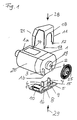
- FIG. 1 there is motor 1 with the shaft end 2 on the encoder side as a cylindrical component with a flattened top and bottom 1a, 1b.
- On the flattened side 1b are two bore connections 3, 4 in the motor housing for the connection introduced to the circuit board 5.
- the printed circuit board 5 comprises the two contact pins 6, 7 for insertion into the bore connections 3, 4 still electronic Components such as resistor 8, sensor-emitter unit 9 and Connector 10. Other components such as the conductor tracks are arranged on the invisible back of the circuit board.
- bracket-like fastening device 11 from above - that is, from the circuit board 5 opposite Side of the motor 1a - in the direction of the arrow on the Motor 1 inserted and with the pin ends 12, 13, 14 in accordingly trained guide slots 15, 1-6, 17 on the Printed circuit board 5 put together.
- the actual strength is preserved the connection by mechanical twisting or bending the pin ends 12, 13, 14 or thermally by soldering, what can be done in one operation.
- a semicircular neckline 18 catered for.
- a stop surface for a perfect fit Introduction serves a cylindrical flange 19 at the shaft end 2.
- a side surface 20 is a further stop surface of the electric motor 1 provided by an angled End 21 of the bracket-like attachment 11 is gripped.
- FIGs 2, 3 and 4 show the motor sensor system according to the invention assembled from 3 different Perspectives.
- the motor 1 with the bracket-like Fastening device 11 shown in side view, in addition a gear side 22 with shaft and pinion 23, 24 for mechanical connection with other control units of the encoder system is indicated.
- the circuit board is located on the underside of motor 1 5 with sensor-emitter unit 9 and a foot end of the contact pin 7 and the pin ends 12, 14 of the holding device 11. There is also a timing disk 25 with a timing disk hub 26 shown in side view.
- the timing disk and the timing disk hub 25, 26 are also recognizable in the front view of the engine 1 according to FIG. 3. Furthermore is the front of the holding device 11 with the front pin ends 12, 13 and - somewhat covered the rear Pin end 14 shown.
Landscapes
- Engineering & Computer Science (AREA)
- Power Engineering (AREA)
- Microelectronics & Electronic Packaging (AREA)
- Control Of Electric Motors In General (AREA)
- Motor Or Generator Frames (AREA)
Abstract
Description
- Figur 1
- das erfindungsgemäße Motor-Sensor-System vor dem Zusammenbau
- Figur 2
- erfindungsgemäßes Motor-Sensor-System in Seitenansicht nach dem Zusammenbau
- Figur 3
- Frontalansicht des erfindungsgemäßen Motor-Sensor-Systems
- Figur 4
- perspektivische Ansicht der erfindungsgemäßen Motor-Sensor-Systems
Claims (5)
- Motor-Sensor-System, bestehend aus einem Elektromotor (1) mit encoderseitigem Wellenende (2), einer Befestigungsvorrichtung für den Motor, Anschlüssen für die Energieversorgung und einer Leiterplatte mit Elektronikkomponenten für die Steuerung und Regelung einer Encodereinheit,
dadurch gekennzeichnet, dass auf einer stabilen Leiterplatte(5) mindestens zwei Kontaktstifte (6,7) für die Energieversorgung des Motors und zur Bildung von Kontaktführungen mit entsprechend geformten Bohrungsanschlüssen(3,4) im Motor positioniert sind,
dass der Elektromotor (1) am encoderseitigem Wellenende (2) von einer winkelförmigen Befestigungsklammer (11) umgriffen wird, wobei die Klammerenden als Zapfen(12,13,14) ausgebildet sind, die den Motor an der Stirnseite und zumindest an einer Längsseite in der Leiterplatte (5) verankern
und dass die winkelförmige Befestigungsklammer in der Ebene der Motorstirnfläche eine Anschlagfläche für das encoderseitige Wellenende des Elektromotors aufweist. - Motor-Sensor-System nach Anspruch 1,
dadurch gekennzeichnet, dass der Elektromotor (1) mindestens eine abgeflachte Basisfläche für die Verbindung zur Leiterplatte (5) aufweist und die winkelförmige Befestigungsklammer um den Motor herumgreifend mit der Leiterplatte verbunden ist. - Motor-Sensor-System nach einem der vorhergehenden Ansprüche,
dadurch gekennzeichnet, dass die winkelförmige Befestigungsklammer (11) zusammen mit der Leiterplatte (5) ein den Elektromotor (1) an mindestens 4 Seiten umgreifendes, offenes Gehäuse darstellt. - Motor-Sensor-System nach einem der vorhergehenden Ansprüche,
dadurch gekennzeichnet, dass die 4 Seiten des offenen Gehäuses gebildet werden aus einer Stirnseite, die am encoderseitigen Wellenende (2) des Elektromotors (1) anliegt, und drei miteinander verbundenen Anschlagflächen für die Ober-, Unter- und Seitenfläche des Elektromotors (1). - Motor-Sensor-System nach einem der vorhergehenden Ansprüche,
dadurch gekennzeichnet, dass die Anschlagsfläche der winkelförmigen Befestigungsklammer an der Stirnseite als Kreis oder Kreissegmentfläche ausgebildet ist.
Applications Claiming Priority (2)
| Application Number | Priority Date | Filing Date | Title |
|---|---|---|---|
| DE10164078 | 2001-12-24 | ||
| DE10164078A DE10164078A1 (de) | 2001-12-24 | 2001-12-24 | Motor-Sensor-System |
Publications (3)
| Publication Number | Publication Date |
|---|---|
| EP1324475A2 true EP1324475A2 (de) | 2003-07-02 |
| EP1324475A3 EP1324475A3 (de) | 2004-01-28 |
| EP1324475B1 EP1324475B1 (de) | 2005-11-09 |
Family
ID=7710944
Family Applications (1)
| Application Number | Title | Priority Date | Filing Date |
|---|---|---|---|
| EP02026120A Expired - Lifetime EP1324475B1 (de) | 2001-12-24 | 2002-11-23 | Motor-Sensor-System |
Country Status (7)
| Country | Link |
|---|---|
| US (1) | US7193347B2 (de) |
| EP (1) | EP1324475B1 (de) |
| JP (1) | JP3720021B2 (de) |
| KR (1) | KR100537695B1 (de) |
| AT (1) | ATE309638T1 (de) |
| DE (2) | DE10164078A1 (de) |
| TW (1) | TW588495B (de) |
Cited By (1)
| Publication number | Priority date | Publication date | Assignee | Title |
|---|---|---|---|---|
| US7414238B2 (en) | 2004-09-28 | 2008-08-19 | Mabuchi Motor Co., Ltd. | Optical encoder device for small-sized motor and method of producing the same |
Families Citing this family (11)
| Publication number | Priority date | Publication date | Assignee | Title |
|---|---|---|---|---|
| DE10332167A1 (de) * | 2003-07-15 | 2005-02-10 | Pwb-Ruhlatec Industrieprodukte Gmbh | Encodersystem und Verfahren zur Montage eines Encodersystems |
| DE102004036903B4 (de) * | 2004-07-29 | 2019-07-04 | Pwb Encoders Gmbh | Encoderbaugruppe und Verfahren zur Montage einer Encoderbaugruppe |
| JP4882649B2 (ja) * | 2006-10-03 | 2012-02-22 | 市光工業株式会社 | モーターモジュール組立体 |
| JP5049567B2 (ja) * | 2006-11-24 | 2012-10-17 | キヤノン株式会社 | 駆動装置 |
| JP4964612B2 (ja) * | 2007-02-19 | 2012-07-04 | マブチモーター株式会社 | 小型モータの光学式エンコーダ装置 |
| US9518815B2 (en) * | 2008-08-06 | 2016-12-13 | Haas Automation, Inc. | Rotary position encoder for rotatable shafts |
| JP5397290B2 (ja) * | 2010-03-30 | 2014-01-22 | 株式会社アドヴィックス | 車両用ブレーキ装置の液圧制御装置 |
| CN104067487B (zh) * | 2012-01-31 | 2017-02-22 | Kodenshi株式会社 | 编码器用传感器安装件、圆盘型编码器和带编码器电动机 |
| JP6304096B2 (ja) * | 2015-03-26 | 2018-04-04 | 豊田合成株式会社 | モータ機構 |
| JP6506406B2 (ja) * | 2015-10-21 | 2019-04-24 | 三菱電機株式会社 | 空気調和装置の室外機及び空気調和装置 |
| GB2538197A (en) * | 2016-08-16 | 2016-11-09 | Johnson Electric Sa | PCB mount for an electric motor |
Family Cites Families (4)
| Publication number | Priority date | Publication date | Assignee | Title |
|---|---|---|---|---|
| JPS5963950A (ja) * | 1983-03-18 | 1984-04-11 | Hitachi Ltd | モ−タ−の吊り下げ取付構造 |
| US5155401A (en) * | 1990-06-07 | 1992-10-13 | Canon Kabushiki Kaisha | Recorder motor with attached encoder and cover |
| EP0996213B1 (de) * | 1998-10-14 | 2001-07-04 | Siemens Aktiengesellschaft | Motoranschlussstecker, insbesondere für einen drehzahlstellbaren Kommutatormotor |
| US6534888B1 (en) * | 1999-03-19 | 2003-03-18 | Mannesmann Vdo Ag | Electric motor intended to be fixed to a printed circuit board |
-
2001
- 2001-12-24 DE DE10164078A patent/DE10164078A1/de not_active Withdrawn
-
2002
- 2002-10-22 US US10/278,121 patent/US7193347B2/en not_active Expired - Fee Related
- 2002-11-23 AT AT02026120T patent/ATE309638T1/de not_active IP Right Cessation
- 2002-11-23 EP EP02026120A patent/EP1324475B1/de not_active Expired - Lifetime
- 2002-11-23 DE DE50204844T patent/DE50204844D1/de not_active Expired - Fee Related
- 2002-12-04 TW TW091135237A patent/TW588495B/zh not_active IP Right Cessation
- 2002-12-11 JP JP2002358907A patent/JP3720021B2/ja not_active Expired - Fee Related
- 2002-12-23 KR KR10-2002-0082394A patent/KR100537695B1/ko not_active Expired - Fee Related
Cited By (1)
| Publication number | Priority date | Publication date | Assignee | Title |
|---|---|---|---|---|
| US7414238B2 (en) | 2004-09-28 | 2008-08-19 | Mabuchi Motor Co., Ltd. | Optical encoder device for small-sized motor and method of producing the same |
Also Published As
| Publication number | Publication date |
|---|---|
| US7193347B2 (en) | 2007-03-20 |
| ATE309638T1 (de) | 2005-11-15 |
| HK1059342A1 (zh) | 2004-06-25 |
| EP1324475A3 (de) | 2004-01-28 |
| TW200301609A (en) | 2003-07-01 |
| KR20030055124A (ko) | 2003-07-02 |
| EP1324475B1 (de) | 2005-11-09 |
| US20050179328A1 (en) | 2005-08-18 |
| JP3720021B2 (ja) | 2005-11-24 |
| DE50204844D1 (de) | 2005-12-15 |
| DE10164078A1 (de) | 2003-07-03 |
| TW588495B (en) | 2004-05-21 |
| KR100537695B1 (ko) | 2005-12-19 |
| JP2003199297A (ja) | 2003-07-11 |
Similar Documents
| Publication | Publication Date | Title |
|---|---|---|
| EP1173918B1 (de) | Elektromotor, insbesondere zum heben und senken von scheiben bei kraftfahrzeugen | |
| EP1324475A2 (de) | Motor-Sensor-System | |
| DE102006030135A1 (de) | Vorrichtung zur Montage von Stiften auf einer Leiterplatte | |
| WO2000024237A1 (de) | Halterung | |
| DE4124833C2 (de) | ||
| DE102016224666B4 (de) | Verfahren zur Herstellung einer Fügeverbindung sowie eine Fügeverbindung | |
| DE2839982C2 (de) | Federnder Kontaktbaustein | |
| WO2015052117A1 (de) | Elektronische schaltung | |
| DE19816126A1 (de) | Leiterplatte mit einem Kupplungselement einer Steckvorrichtung | |
| DE10332167A1 (de) | Encodersystem und Verfahren zur Montage eines Encodersystems | |
| DE10107630B4 (de) | Stiftleiste und Sensorsystem für Kraftfahrzeuge mit derartiger Stiftleiste | |
| DE10112427A1 (de) | Elektromotorische Stelleinheit für ein Zumeßsystem einer Brennkraftmaschine | |
| DE20120932U1 (de) | Motor-Sensor-System | |
| EP0766351A1 (de) | Statusanzeigeeinrichtung für Leiterplattenanschlusselemente | |
| DE3518511C1 (de) | Batterie - E-Block - Verbindungsbuegel fuer eine Kleinuhr | |
| DE4405578B4 (de) | Elektronische Baueinheit | |
| DE10129840B4 (de) | Elektrisches Gerät | |
| DE10047153A1 (de) | Befestigungseinrichtung | |
| EP1019675B1 (de) | Messwerk, insbesondere für anzeigeeinrichtung in der kfz-technik | |
| DE2165611B2 (de) | Isolierende Verdrahtungsplatte mit stiftförmigen Verbindungsgliedern und Verfahren zum Montieren von Bauteilen auf einer solchen Verdrahtungsplatte | |
| EP1093970A2 (de) | Stellenantrieb zum Verstellen eines Stellglieds in zumindest zwei Freiheitsgraden | |
| DE10047126A1 (de) | Befestigungseinrichtung | |
| DE3500796C1 (de) | Kontaktstift, insbesondere für Leiterplatten | |
| DE2839611C2 (de) | Verfahren zum Bestücken einer Leiterplatte für ein batteriebetriebenes Gerät mit einem Motor, insbesondere einer Uhr | |
| EP1046199A1 (de) | Elektrische steckverbindung |
Legal Events
| Date | Code | Title | Description |
|---|---|---|---|
| PUAI | Public reference made under article 153(3) epc to a published international application that has entered the european phase |
Free format text: ORIGINAL CODE: 0009012 |
|
| AK | Designated contracting states |
Designated state(s): AT BE BG CH CY CZ DE DK EE ES FI FR GB GR IE IT LI LU MC NL PT SE SK TR |
|
| AX | Request for extension of the european patent |
Extension state: AL LT LV MK RO SI |
|
| 17P | Request for examination filed |
Effective date: 20030722 |
|
| PUAL | Search report despatched |
Free format text: ORIGINAL CODE: 0009013 |
|
| AK | Designated contracting states |
Kind code of ref document: A3 Designated state(s): AT BE BG CH CY CZ DE DK EE ES FI FR GB GR IE IT LI LU MC NL PT SE SK TR |
|
| AX | Request for extension of the european patent |
Extension state: AL LT LV MK RO SI |
|
| REG | Reference to a national code |
Ref country code: HK Ref legal event code: DE Ref document number: 1059342 Country of ref document: HK |
|
| 17Q | First examination report despatched |
Effective date: 20040617 |
|
| AKX | Designation fees paid |
Designated state(s): AT BE BG CH CY CZ DE DK EE ES FI FR GB GR IE IT LI LU MC NL PT SE SK TR |
|
| GRAP | Despatch of communication of intention to grant a patent |
Free format text: ORIGINAL CODE: EPIDOSNIGR1 |
|
| GRAS | Grant fee paid |
Free format text: ORIGINAL CODE: EPIDOSNIGR3 |
|
| GRAA | (expected) grant |
Free format text: ORIGINAL CODE: 0009210 |
|
| AK | Designated contracting states |
Kind code of ref document: B1 Designated state(s): AT BE BG CH CY CZ DE DK EE ES FI FR GB GR IE IT LI LU MC NL PT SE SK TR |
|
| PG25 | Lapsed in a contracting state [announced via postgrant information from national office to epo] |
Ref country code: NL Free format text: LAPSE BECAUSE OF FAILURE TO SUBMIT A TRANSLATION OF THE DESCRIPTION OR TO PAY THE FEE WITHIN THE PRESCRIBED TIME-LIMIT Effective date: 20051109 Ref country code: SK Free format text: LAPSE BECAUSE OF FAILURE TO SUBMIT A TRANSLATION OF THE DESCRIPTION OR TO PAY THE FEE WITHIN THE PRESCRIBED TIME-LIMIT Effective date: 20051109 Ref country code: TR Free format text: LAPSE BECAUSE OF FAILURE TO SUBMIT A TRANSLATION OF THE DESCRIPTION OR TO PAY THE FEE WITHIN THE PRESCRIBED TIME-LIMIT Effective date: 20051109 Ref country code: EE Free format text: LAPSE BECAUSE OF FAILURE TO SUBMIT A TRANSLATION OF THE DESCRIPTION OR TO PAY THE FEE WITHIN THE PRESCRIBED TIME-LIMIT Effective date: 20051109 Ref country code: IE Free format text: LAPSE BECAUSE OF FAILURE TO SUBMIT A TRANSLATION OF THE DESCRIPTION OR TO PAY THE FEE WITHIN THE PRESCRIBED TIME-LIMIT Effective date: 20051109 Ref country code: FI Free format text: LAPSE BECAUSE OF FAILURE TO SUBMIT A TRANSLATION OF THE DESCRIPTION OR TO PAY THE FEE WITHIN THE PRESCRIBED TIME-LIMIT Effective date: 20051109 Ref country code: CZ Free format text: LAPSE BECAUSE OF FAILURE TO SUBMIT A TRANSLATION OF THE DESCRIPTION OR TO PAY THE FEE WITHIN THE PRESCRIBED TIME-LIMIT Effective date: 20051109 |
|
| REG | Reference to a national code |
Ref country code: GB Ref legal event code: FG4D Free format text: NOT ENGLISH |
|
| REG | Reference to a national code |
Ref country code: CH Ref legal event code: EP |
|
| PG25 | Lapsed in a contracting state [announced via postgrant information from national office to epo] |
Ref country code: CY Free format text: LAPSE BECAUSE OF FAILURE TO SUBMIT A TRANSLATION OF THE DESCRIPTION OR TO PAY THE FEE WITHIN THE PRESCRIBED TIME-LIMIT Effective date: 20051123 Ref country code: AT Free format text: LAPSE BECAUSE OF NON-PAYMENT OF DUE FEES Effective date: 20051123 |
|
| PG25 | Lapsed in a contracting state [announced via postgrant information from national office to epo] |
Ref country code: MC Free format text: LAPSE BECAUSE OF NON-PAYMENT OF DUE FEES Effective date: 20051130 Ref country code: BE Free format text: LAPSE BECAUSE OF NON-PAYMENT OF DUE FEES Effective date: 20051130 |
|
| REG | Reference to a national code |
Ref country code: IE Ref legal event code: FG4D Free format text: LANGUAGE OF EP DOCUMENT: GERMAN |
|
| REF | Corresponds to: |
Ref document number: 50204844 Country of ref document: DE Date of ref document: 20051215 Kind code of ref document: P |
|
| PG25 | Lapsed in a contracting state [announced via postgrant information from national office to epo] |
Ref country code: LU Free format text: LAPSE BECAUSE OF NON-PAYMENT OF DUE FEES Effective date: 20060109 |
|
| PG25 | Lapsed in a contracting state [announced via postgrant information from national office to epo] |
Ref country code: BG Free format text: LAPSE BECAUSE OF FAILURE TO SUBMIT A TRANSLATION OF THE DESCRIPTION OR TO PAY THE FEE WITHIN THE PRESCRIBED TIME-LIMIT Effective date: 20060209 Ref country code: SE Free format text: LAPSE BECAUSE OF FAILURE TO SUBMIT A TRANSLATION OF THE DESCRIPTION OR TO PAY THE FEE WITHIN THE PRESCRIBED TIME-LIMIT Effective date: 20060209 Ref country code: DK Free format text: LAPSE BECAUSE OF FAILURE TO SUBMIT A TRANSLATION OF THE DESCRIPTION OR TO PAY THE FEE WITHIN THE PRESCRIBED TIME-LIMIT Effective date: 20060209 Ref country code: GR Free format text: LAPSE BECAUSE OF FAILURE TO SUBMIT A TRANSLATION OF THE DESCRIPTION OR TO PAY THE FEE WITHIN THE PRESCRIBED TIME-LIMIT Effective date: 20060209 |
|
| PG25 | Lapsed in a contracting state [announced via postgrant information from national office to epo] |
Ref country code: ES Free format text: LAPSE BECAUSE OF FAILURE TO SUBMIT A TRANSLATION OF THE DESCRIPTION OR TO PAY THE FEE WITHIN THE PRESCRIBED TIME-LIMIT Effective date: 20060220 |
|
| PG25 | Lapsed in a contracting state [announced via postgrant information from national office to epo] |
Ref country code: PT Free format text: LAPSE BECAUSE OF FAILURE TO SUBMIT A TRANSLATION OF THE DESCRIPTION OR TO PAY THE FEE WITHIN THE PRESCRIBED TIME-LIMIT Effective date: 20060410 |
|
| NLV1 | Nl: lapsed or annulled due to failure to fulfill the requirements of art. 29p and 29m of the patents act | ||
| REG | Reference to a national code |
Ref country code: HK Ref legal event code: GR Ref document number: 1059342 Country of ref document: HK |
|
| GBT | Gb: translation of ep patent filed (gb section 77(6)(a)/1977) |
Effective date: 20060516 |
|
| REG | Reference to a national code |
Ref country code: IE Ref legal event code: FD4D |
|
| ET | Fr: translation filed | ||
| PLBE | No opposition filed within time limit |
Free format text: ORIGINAL CODE: 0009261 |
|
| STAA | Information on the status of an ep patent application or granted ep patent |
Free format text: STATUS: NO OPPOSITION FILED WITHIN TIME LIMIT |
|
| 26N | No opposition filed |
Effective date: 20060810 |
|
| PG25 | Lapsed in a contracting state [announced via postgrant information from national office to epo] |
Ref country code: LI Free format text: LAPSE BECAUSE OF NON-PAYMENT OF DUE FEES Effective date: 20061130 Ref country code: CH Free format text: LAPSE BECAUSE OF NON-PAYMENT OF DUE FEES Effective date: 20061130 |
|
| REG | Reference to a national code |
Ref country code: CH Ref legal event code: PL |
|
| BERE | Be: lapsed |
Owner name: PWB-RUHLATEC INDUSTRIEPRODUKTE G.M.B.H. Effective date: 20051130 |
|
| PGFP | Annual fee paid to national office [announced via postgrant information from national office to epo] |
Ref country code: IT Payment date: 20081125 Year of fee payment: 7 |
|
| PGFP | Annual fee paid to national office [announced via postgrant information from national office to epo] |
Ref country code: FR Payment date: 20081118 Year of fee payment: 7 |
|
| PGFP | Annual fee paid to national office [announced via postgrant information from national office to epo] |
Ref country code: DE Payment date: 20090128 Year of fee payment: 7 |
|
| PGFP | Annual fee paid to national office [announced via postgrant information from national office to epo] |
Ref country code: GB Payment date: 20081121 Year of fee payment: 7 |
|
| GBPC | Gb: european patent ceased through non-payment of renewal fee |
Effective date: 20091123 |
|
| REG | Reference to a national code |
Ref country code: FR Ref legal event code: ST Effective date: 20100730 |
|
| PG25 | Lapsed in a contracting state [announced via postgrant information from national office to epo] |
Ref country code: FR Free format text: LAPSE BECAUSE OF NON-PAYMENT OF DUE FEES Effective date: 20091130 |
|
| PG25 | Lapsed in a contracting state [announced via postgrant information from national office to epo] |
Ref country code: DE Free format text: LAPSE BECAUSE OF NON-PAYMENT OF DUE FEES Effective date: 20100601 |
|
| PG25 | Lapsed in a contracting state [announced via postgrant information from national office to epo] |
Ref country code: GB Free format text: LAPSE BECAUSE OF NON-PAYMENT OF DUE FEES Effective date: 20091123 |
|
| PG25 | Lapsed in a contracting state [announced via postgrant information from national office to epo] |
Ref country code: IT Free format text: LAPSE BECAUSE OF NON-PAYMENT OF DUE FEES Effective date: 20091123 |