EP1324631A2 - Zeitgebersystem für Datenkommunikation mit kombinierter Nutzung - Google Patents
Zeitgebersystem für Datenkommunikation mit kombinierter Nutzung Download PDFInfo
- Publication number
- EP1324631A2 EP1324631A2 EP02293214A EP02293214A EP1324631A2 EP 1324631 A2 EP1324631 A2 EP 1324631A2 EP 02293214 A EP02293214 A EP 02293214A EP 02293214 A EP02293214 A EP 02293214A EP 1324631 A2 EP1324631 A2 EP 1324631A2
- Authority
- EP
- European Patent Office
- Prior art keywords
- data
- expiry time
- outgoing
- connection
- list
- Prior art date
- Legal status (The legal status is an assumption and is not a legal conclusion. Google has not performed a legal analysis and makes no representation as to the accuracy of the status listed.)
- Withdrawn
Links
Images


Classifications
-
- H—ELECTRICITY
- H04—ELECTRIC COMMUNICATION TECHNIQUE
- H04L—TRANSMISSION OF DIGITAL INFORMATION, e.g. TELEGRAPHIC COMMUNICATION
- H04L12/00—Data switching networks
- H04L12/54—Store-and-forward switching systems
- H04L12/56—Packet switching systems
- H04L12/5601—Transfer mode dependent, e.g. ATM
-
- H—ELECTRICITY
- H04—ELECTRIC COMMUNICATION TECHNIQUE
- H04L—TRANSMISSION OF DIGITAL INFORMATION, e.g. TELEGRAPHIC COMMUNICATION
- H04L12/00—Data switching networks
- H04L12/54—Store-and-forward switching systems
- H04L12/56—Packet switching systems
- H04L12/5601—Transfer mode dependent, e.g. ATM
- H04L2012/5638—Services, e.g. multimedia, GOS, QOS
- H04L2012/5646—Cell characteristics, e.g. loss, delay, jitter, sequence integrity
- H04L2012/5649—Cell delay or jitter
-
- H—ELECTRICITY
- H04—ELECTRIC COMMUNICATION TECHNIQUE
- H04L—TRANSMISSION OF DIGITAL INFORMATION, e.g. TELEGRAPHIC COMMUNICATION
- H04L12/00—Data switching networks
- H04L12/54—Store-and-forward switching systems
- H04L12/56—Packet switching systems
- H04L12/5601—Transfer mode dependent, e.g. ATM
- H04L2012/5638—Services, e.g. multimedia, GOS, QOS
- H04L2012/5646—Cell characteristics, e.g. loss, delay, jitter, sequence integrity
- H04L2012/5652—Cell construction, e.g. including header, packetisation, depacketisation, assembly, reassembly
- H04L2012/5653—Cell construction, e.g. including header, packetisation, depacketisation, assembly, reassembly using the ATM adaptation layer [AAL]
- H04L2012/5656—Cell construction, e.g. including header, packetisation, depacketisation, assembly, reassembly using the ATM adaptation layer [AAL] using the AAL2
-
- H—ELECTRICITY
- H04—ELECTRIC COMMUNICATION TECHNIQUE
- H04L—TRANSMISSION OF DIGITAL INFORMATION, e.g. TELEGRAPHIC COMMUNICATION
- H04L12/00—Data switching networks
- H04L12/54—Store-and-forward switching systems
- H04L12/56—Packet switching systems
- H04L12/5601—Transfer mode dependent, e.g. ATM
- H04L2012/5638—Services, e.g. multimedia, GOS, QOS
- H04L2012/5671—Support of voice
-
- H—ELECTRICITY
- H04—ELECTRIC COMMUNICATION TECHNIQUE
- H04L—TRANSMISSION OF DIGITAL INFORMATION, e.g. TELEGRAPHIC COMMUNICATION
- H04L12/00—Data switching networks
- H04L12/54—Store-and-forward switching systems
- H04L12/56—Packet switching systems
- H04L12/5601—Transfer mode dependent, e.g. ATM
- H04L2012/5678—Traffic aspects, e.g. arbitration, load balancing, smoothing, buffer management
- H04L2012/5681—Buffer or queue management
- H04L2012/5682—Threshold; Watermark
Definitions
- This invention relates to telecommunication equipment.
- the invention has application in asynchronous transfer mode (ATM) devices.
- ATM asynchronous transfer mode
- the invention relates specifically to combined use timers which may be used in combining data into the cells of an ATM connection.
- An ATM connection transmits fixed- length data cells over a physical data link.
- the physical data link typically comprises a fiber optic cable or an electrical cable.
- the ATM link is typically divided up into a number of virtual connections. In various situations it is desirable to combine data belonging to one or more channels into one ATM virtual connection which has sufficient bandwidth to service all of the channels.
- the ATM link is a step in carrying the stream of data from a source to an ultimate destination.
- each ATM virtual connection data is carried as a payload in ATM cells.
- the data in each channel may arrive in packets which are not the same size as the data payload of an ATM cell and may not be an even multiple of the size of the ATM cell data payload. Further, in some cases, packets of data may arrive for transmission across an ATM link in a bursty manner. To conserve bandwidth in the ATM link, some protocols permit delaying the transmission of a partially filled ATM cell until more data arrives from which the partially filled cell can be filled and then sent.
- latency i.e. the time taken for each part of a data stream to be transmitted to its destination
- delay across the network must be minimal.
- the international telecommunications union (ITU-T) standard I.363.2 provides mechanisms to enforce an upper bound to the time within which any unfilled ATM cells should be dispatched across an ATM link, even if the cells are not yet filled with data.
- This standard relates to combining multiple ATM adaptation layer 2 (AAL2) coded packets into the cells of a single ATM connection. The packets being combined together may be multiplexed from multiple channels.
- AAL2 coded ATM connection shall be equipped with a combined use (CU) timer which measures the delay interval starting at the time that the first data is placed in an ATM cell.
- a controller monitors the CU timer for each connection and causes any partially filled cell to be sent after a maximum predetermined delay has been reached. Cells which become completely filled before the maximum predetermined delay has been reached are sent without waiting for the maximum predetermined delay to elapse.
- a separate timer is typically required for each connection, the number of timers required may be very large.
- a channelized OC-3 interface might contain up to 2016 channels. If 10 channels are used for each AAL2 connection then there could be a need for as many as approximately 200 CU timers. Implementing such a large number of CU timers in a cost efficient and practical manner presents a significant problem. In some cases even more CU timers will be required.
- One object of the present invention is to provide a method for controlling the dispatch of data to a plurality of destinations on a telecommunication network which can be effectively used in cases where many CU timers are required.
- the invention provides a method for controlling the dispatch of data on a telecommunication network, the method comprising the steps of:
- a device such as a combined use CU timer system establishes expiry times by which partially filled cells in each of a number of data streams should be transmitted.
- a record is kept of groups of one or more data streams which share the same expiry time.
- the invention facilitates tracking expiry times for a large number of data streams. Implementations of the invention may be used in sending AAL2 packets over ATM links according to the I.363.2 standard.
- Associating the destination with the expiry time may comprise placing information identifying the destination in a list associated with the expiry time.
- the list comprises a linked list.
- the linked list comprises a doubly linked list.
- Another aspect of the invention provides a method for controlling the transmission of fixed-sized data cells on a telecommunication link.
- the method comprises: receiving a plurality of data streams at an interface to the telecommunication link; assigning data from the data streams into fixed-size cells for transmission across connections in the telecommunication link; upon the creation of a partially-filled cell to be transmitted on a connection, scheduling an expiry time for the partially-filled cell and associating the connection with the expiry time; and, when the expiry time occurs, using the association to identify a group of one or more connections for which there are partially-filled cells all associated with the expiry time and dispatching the partially- filled cells in the group.
- the telecommunication link comprises an ATM virtual channel connection and the fixed-size cells comprise ATM cells.
- the apparatus comprises a plurality of interfaces, each interface receiving one or more streams of data and places the received data into data packets for transmission across a telecommunications link.
- the apparatus comprises a outgoing cell assembler connected to place data packets onto the telecommunications link and a combined use timer connected to control the transmission of partially- filled data packets over the telecommunications link.
- Each of the interfaces is configured to provide a partial packet ready signal to the combined use timer upon the creation of a partially-filled data packet containing less than a threshold amount of data.
- the combined use timer comprises a timer maintaining a current time value, a calculator connected to determine an expiry time for a partially-filled packet corresponding to a partial packet ready signal, a data structure capable of holding information identifying groups of partially-filled packets which share a common expiry time and comparison logic connected to signal to the outgoing cell assembler when the expiry time for a group of one or more partially- filled packets which share a common expiry time has occurred.
- FIG. 1 shows a block diagram of a system 10 according to one implementation of the invention.
- System 10 transmits data belonging to an outgoing channel over an ATM virtual connection 12 in a data link 13.
- Data link 13 may, for example, comprise a fiber optic cable, an electrical cable, a wireless ATM link, or the like. The nature of the physical layer is not particularly important to this invention.
- One or more streams 14 of data are received at an interface 16 of system 10 for transmission over ATM virtual connection 12.
- System 10 comprises one or more additional interfaces 16 which are not shown in Figure 1.
- Each interface 16 handles data belonging to an outgoing channel.
- the data for each outgoing channel is passed on to some destination.
- the data for each outgoing channel may be destined for a certain connection, logical address, queue, path or the like. Multiple outgoing channels may have destinations on the same physical device.
- data for the outgoing channel associated with interface 16 is carried toward its ultimate destination on ATM virtual connection 12.
- an interface 16 of system 10 receives a plurality of data streams 14 each comprising a separate time domain multiplexing (TDM) channel in an incoming data link 15.
- TDM time domain multiplexing
- the source of data streams 14 is not particularly germane to this invention. Where multiple data streams 14 are received at system 10, the data streams may be received over separate physical data links or may be multiplexed on a single data link, as shown.
- the illustrated interface 16 has only three incoming data streams 14. In some implementations of the invention there may be many more incoming data streams 14. For example, there might be several hundred or even several thousand incoming data streams 14 by which data is received at interface 16.
- Interface 16 receives the one or more incoming data streams 14 and provides an adaptation function.
- interface 16 provides for each incoming data stream 14 a processing function 18, which may perform processing required by data of the data stream, and a packetization function 19, which places the data of the data stream 14 into AAL2 packets 20.
- AAL2 packets 20 are delivered to an outgoing cell assembler 22 which, in the illustrated embodiment also serves as a multiplexer.
- Outgoing cell assembler 22 places the AAL2 packets into ATM cells 24. There is typically not a one-to-one correspondence between AAL2 packets and ATM cells 24. Some AAL2 packets might fit entirely in one ATM cell 24 others might be split between two or more ATM cells 24.
- ATM cells 24 are carried on ATM virtual connection 12.
- ATM virtual connection 12 is combined with other ATM virtual connections from other adaptation functions in ATM cell switch 20 for transmission over data link 13.
- outgoing cell assembler 22 When outgoing cell assembler 22 has a filled ATM cell 24 it sends the ATM cell 24 on ATM virtual connection 12. Outgoing cell assembler 22 defers sending ATM cells 24 which are not filled.
- a CU timer system 30 causes outgoing cell assembler 22 to send ATM cells 24, even if they are still only partially filled, before the data in the partially- filled ATM cells 24 is delayed excessively.
- outgoing cell assembler 22 When outgoing cell assembler 22 has a partially filled ATM cell 24, it generates a partial cell available signal 32 which it sends to CU timer system 30.
- CU timer system 30 is common to a plurality of interfaces 16. Interfaces 16 may share common hardware elements.
- CU timer system 30 comprises a timer 36 and an expiry time calculator 38.
- expiry time calculator 38 establishes a time by which the cell being filled by outgoing cell assembler 22 should be transmitted, even if it is still not full.
- the time may be established, for example, by adding an amount to the current value of the time maintained by timer 36.
- the amount may be, for example, a fixed amount or an amount specified by a value which may be independently configured for each interface 16 or each ATM virtual connection 12.
- a data structure 40 is used to keep track of the expiry time(s) for any interfaces 16 from which a partial cell available signal 32 has been received.
- Logic 42 identifies those partially filled ATM cells 24 referenced in data structure 40 which have an expiry time equal to the current time maintained by timer 36. Logic 42 generates a send packet signal 33 to the appropriate outgoing cell assembler 22 which causes outgoing cell assembler 22 to forward its partially filled ATM cell 24 immediately for transmission on ATM virtual connection 12. Outgoing cell assembler 24 may pad the unfilled portion of the payload of the ATM cell 24 with, for example, zeros.
- System 10 preferably comprises a means for removing from data structure 40 references to ATM cells 24 which become filled after a partial cell available signal 32 has been generated but before their expiry times.
- each of interfaces 16 is configured to generate a cell sent signal 34.
- Cell sent signal 34 is generated when a partially filled ATM cell 24 becomes filled and can therefore be sent without delay.
- CU timer system 30 receives the cell sent signals 34. Upon receipt of a cell sent signal 34, logic 44 in CU timer system 30 deletes reference to the cell from data structure 40.
- Data structure 40 preferably comprises a record which identifies each partially filled ATM cell 24 for which an expiry time has been set.
- the record preferably associates together the records of those partially filled ATM cells 24 whose expiry times are the same (or fall within the same window).
- Data structure 40 may comprise a series of lists, each list containing a record of all ATM virtual connections which comprise partially filled ATM cells 24 that are scheduled to expire at the same expiry time. Each list may be implemented, for example, as a linked list.
- logic 42 retrieves from data structure 40 information identifying any ATM cells 24 which should be transmitted at that time increment. For each cell that is scheduled to be transmitted at that time increment, logic 42 generates and delivers to the appropriate outgoing cell assembler 22 a send now signal 33 indicating that the ATM cell 24 should be transmitted without further delay.
- CU timer system 30 may be implemented, for example, in an application specific integrated circuit (ASIC) or in a field programmable gate array (FPGA).
- CU timer system 30 may comprise a number of discrete memory components or regions, with one memory component or region set aside for each potential expiry time.
- CU timer system 30 could include one or more memories which each include lists of partially filled ATM cells 24. One list is provided for each distinct expiry time or window.
- CU timer system 30 may include a single memory for holding all of data structure 40.
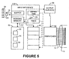
- FIGs 3, 4 and 5 illustrate a specific embodiment of the invention.
- an interface 116 comprising control logic circuits receives packets 20 arising from one or more data streams 14 on an incoming data link 15. Data in each of the data streams is destined for an outgoing channel carried by one of a plurality of ATM virtual connections 12.
- Each data stream 14 may comprise a series of data packets.
- the data packets could, for example, comprise coded voice information, coded video information, segmented ethernet packets, segmented IP packets, or packets in some other format.
- a record 50 as shown in Figure 3 is maintained in a suitable memory 52.
- interface 116 inspects the packet's header to determine which ATM virtual connection it should be forwarded to.
- Interface 116 selects the instance of record 50 for that ATM virtual connection.
- Interface 116 may load the instance of record 50 into a working memory 127.
- each record 50 includes several fields including the following:
- interface 116 Upon receiving data destined for a particular ATM virtual connection 12, interface 116 loads the appropriate record 50 into working memory 127 and then begins assembling the received data into the DATA area.
- the first byte of the DATA area is taken up with an AAL2 START FIELD which includes information about the ATM cell such as an OSF (offset), SN (sequence number) and P (parity) fields as defined in the I.363.2 standard.
- OSF offset
- SN sequence number
- P parity
- interface 116 When interface 116 has a partially filled ATM cell in the DATA area for the current record 50 and there is no more data immediately available to fill the ATM cell then interface 116 computes an expiry time for the partially filled cell by adding the value in the MAX TIME field to the current value maintained by timer 126. The resulting expiry time is used to store a reference to the current record 50 in CU timer memory 40.
- CU timer memory 40 comprises a location corresponding to each possible upcoming expiry time.
- Each bcation in CU timer memory 40 can hold information identifying a record 50 corresponding to an ATM connection for which there is a partially filled cell having an expiry time corresponding to the location.
- the information may comprise, for example, a pointer to the location of the record 50 in memory 52.
- interface 116 writes information identifying the current record 50 to the location in CU timer memory 40 corresponding to the expiry time for the partially filled packet. If there is already another data stream referenced at that location in CU timer memory 40 (i.e. a previously processed ATM connection has a partially filled ATM cell which shares the same expiry time) then interface 116 copies the pointer to the record 50 of the previously processed connection to the NEXT CONNECTION IN LIST field of the current record 50.
- linked lists 130 are built up. Each linked list contains references to those ATM connections which have partially filled ATM cells having the same expiry time.
- the head of each linked list is a location in CU timer memory 40 which corresponds to the expiry time.
- each linked list is preferably a doubly-linked list.
- interface 116 when a location in CU timer memory 40 includes a pointer to a previously inserted record 50 then interface 116 writes a pointer to the current record 50 in the PREVIOUS CONNECTION IN LIST field of the previously inserted record 50.
- Figure 4 shows an example in which CU timer memory 40 is tracking 5 groups each containing one or more ATM connections which share the same expiry time. Each of these groups is represented by a doubly linked list 130.
- location 140A of CU timer memory 40 contains a pointer to the record 50C for a connection "C”.
- the PREVIOUS CONNECTION IN LIST field contains a pointer to location 140A of CU timer memory 40
- the NEXT CONNECTION IN LIST field contains a pointer to the record 50D for a connection "D”.
- the PREVIOUS CONNECTION IN LIST field contains a pointer to record 50C and the NEXT CONNECTION IN LIST field contains a pointer to the record 50E for a connection "E”.
- the PREVIOUS CONNECTION IN LIST field contains a pointer to record 50D and the NEXT CONNECTION IN LIST field contains a null pointer.
- Memory 52 may contain records 50 for ATM connections which do not have partially filled packets.
- Figure 4 shows records 50J, 50K, and 50L which are not linked directly or indirectly to any location in CU timer memory 40.
- both the PREVIOUS CONNECTION IN LIST field and the NEXT CONNECTION IN LIST field may contain null pointers.
- timer 126 tracks the current time.
- a current time pointer (Fig. 4) identifies the location in CU timer memory 40 which corresponds to the current time.
- a timeout pointer (Fig. 5) may also be provided. The timeout pointer typically points to the same location in CU timer memory 40 as the current time pointer. The timeout pointer points to the location in CU timer memory 40 to which any records 50 which are currently being processed are linked.
- the current time pointer and timeout pointer move sequentially through the locations of CU timer memory 40. It takes some time to process each record 50. When a large number of connections have cells expiring at the same or closely spaced expiry times the timeout pointer may lag behind the current time pointer by one or more locations in CU timer memory 40. Where there is sufficient processing capacity to process all connections which could expire at any particular expiry time before the next expiry time then a timeout pointer is not required.
- interface 116 checks to see if that location holds a pointer to a record 50. If not, there are no partially filled ATM cells which have expiry times which require them to be sent immediately. If there is a pointer to a record 50 then interface 116 retrieves the pointed-to record 50 from memory 52 and places the data in it into an ATM cell in an output queue 56. Interface 116 continues to send unfilled ATM cells for all of the connections having records 50 identified in the linked list 130 having its head at the location in CU timer memory 40 which is pointed to by the timeout pointer. When this has been completed then a null pointer is inserted into the location in CU timer memory 40.
- timeout pointer If the timeout pointer is not pointing to the same location in CU timer memory 40 as the current time pointer, and there are no records 50 pointed to by the location in CU timer memory 40 identified by the timeout pointer, then the timeout pointer moves to the next location in CU timer memory 40 and the steps described in this paragraph are repeated.
- Interface 116 can accomplish this by retrieving the record 50 for the data stream and identifying all pointers to that record 50 in the doubly linked list 130. This can be done by identifying:
- the apparatus of Figure 5 may be implemented in an application specific integrated circuit ASIC or an FPGA. It is convenient to include working memory 127 and CU timer memory 40 in the ASIC or FPGA.
- Memory 52 may comprise an external memory, for example, an SRAM memory.
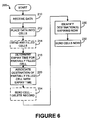
- Figure 6 illustrates a method 200 according to the invention.
- Method 200 receives data for a plurality of data streams at an interface to a telecommunication link (block 210).
- the data is placed into cells for transmission across specific channels in the telecommunication link.
- Block 214 sends any filled cells across the corresponding channel in the telecommunication link (block 214 may comprise placing the filled cells into a queue or queues for transmission across the telecommunication link).
- Block 216 determines an expiry time for any partially filled cells.
- a record is made associating the connection over which the partially filled cell will be sent with the expiry time determined in block 216. If the partially filled cell becomes filled before the expiry time then in block 224 the filled cell is sent and the record previously made in block 220 is deleted. Upon the expiry time being reached, the record made in block 220 is used to identify the connection with which the partially filled cell is associated together with any other connections having partially filled cells sharing the same expiry time (block 230). Then the group of one or more partially filled cells which share the expiry time are sent on the appropriate connections (block 232).
- the invention provides a general method for controlling the dispatch of data onto multiple connections in one or more telecommunication links where it is desirable that:
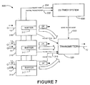
- FIG. 7 illustrates apparatus 300 according to one of many possible alternative embodiments of the invention.
- Apparatus 300 comprises a plurality of interfaces 316 which each receive data from one or more sources 14.
- An interface 316 is provided for each of a plurality of outgoing channels.
- the way in which data 14 arrives at interfaces 316 and the format in which data 14 arrives at interfaces 316 is implementation-specific.
- data is held in a buffer 317 in preparation for dispatching to a destination in the form of data packets 24'.
- Data packets 24' may comprise fixed-size cells, fixed size data frames, variable-size packets.
- Each interface 316 constitutes an outgoing packet assembler (which could also be termed an outgoing cell assembler in cases where packets 24' comprise cells).
- a transmitter 320 retrieves from interfaces 316 and forwards data packets 24' when they are ready for sending.
- a data packet 24' is ready for sending when it either: contains more than a threshold amount of data; or contains data for which an expiry
- interface 316 When data arrives at an interface 316 it is placed into buffer 317. If there is at least a threshold amount of data in buffer 317 then interface 316 causes a PACKET FULL signal 319 to be sent to transmitter 320. Transmitter 320 retrieves and transmits packets 24' from the interface 316 as long as the PACKET FULL signal is asserted. When data which will start a new packet 24' but will leave the new packet 24' with less than a threshold amount of data arrives at interface 316 then interface 316 causes a PARTIAL PACKET ready signal 332 to be sent to CU timer system 330. The PARTIAL PACKET READY signal may be sent, for example, when:
- CU timer system 330 may function in substantially the same way as the CU timer system 30 shown in Figure 2.
- CU timer system Upon the expiry time for the data of any one of interfaces 316, CU timer system delivers a SEND PACKET NOW signal 333 to transmitter 320.
- the SEND PACKET NOW signal identifies the interface 316 for which the data should be sent (even though the threshold amount of data may not be available at that interface).
- Transmitter 320 then dispatches a packet 18 containing whatever data is present in buffer 317 of the interface 316.
- interface 316 causes a packet sent signal 334 to be delivered to CU timer system 330.
Landscapes
- Engineering & Computer Science (AREA)
- Computer Networks & Wireless Communication (AREA)
- Signal Processing (AREA)
- Data Exchanges In Wide-Area Networks (AREA)
Applications Claiming Priority (2)
| Application Number | Priority Date | Filing Date | Title |
|---|---|---|---|
| US26860 | 2001-12-27 | ||
| US10/026,860 US20030123451A1 (en) | 2001-12-27 | 2001-12-27 | Combined use timer system for data communication |
Publications (2)
| Publication Number | Publication Date |
|---|---|
| EP1324631A2 true EP1324631A2 (de) | 2003-07-02 |
| EP1324631A3 EP1324631A3 (de) | 2003-08-13 |
Family
ID=21834194
Family Applications (1)
| Application Number | Title | Priority Date | Filing Date |
|---|---|---|---|
| EP02293214A Withdrawn EP1324631A3 (de) | 2001-12-27 | 2002-12-23 | Zeitgebersystem für Datenkommunikation mit kombinierter Nutzung |
Country Status (2)
| Country | Link |
|---|---|
| US (1) | US20030123451A1 (de) |
| EP (1) | EP1324631A3 (de) |
Families Citing this family (9)
| Publication number | Priority date | Publication date | Assignee | Title |
|---|---|---|---|---|
| US7158527B2 (en) * | 2002-04-02 | 2007-01-02 | Telefonaktiebolaget Lmeericsson (Publ) | Protocol multiplexing |
| US7685287B2 (en) * | 2002-05-30 | 2010-03-23 | Microsoft Corporation | Method and system for layering an infinite request/reply data stream on finite, unidirectional, time-limited transports |
| GB0409582D0 (en) * | 2004-04-29 | 2004-06-02 | British Telecomm | Event notification network |
| CN100466596C (zh) * | 2004-06-27 | 2009-03-04 | 华为技术有限公司 | 实现联合使用定时器功能的系统及其方法 |
| CN101002443A (zh) * | 2004-08-12 | 2007-07-18 | 皇家飞利浦电子股份有限公司 | 用于在集成电路中将数据分配给至少一个分组的方法 |
| US7627004B2 (en) * | 2005-05-26 | 2009-12-01 | Cisco Technology, Inc. | Transporting synchronization channel information across a packet network |
| US7768939B1 (en) * | 2007-01-02 | 2010-08-03 | Juniper Networks, Inc. | Network proxy with asymmetric connection connectivity |
| US7769015B2 (en) * | 2007-09-11 | 2010-08-03 | Liquid Computing Corporation | High performance network adapter (HPNA) |
| US9237034B2 (en) * | 2008-10-21 | 2016-01-12 | Iii Holdings 1, Llc | Methods and systems for providing network access redundancy |
Family Cites Families (8)
| Publication number | Priority date | Publication date | Assignee | Title |
|---|---|---|---|---|
| US5598535A (en) * | 1994-08-01 | 1997-01-28 | International Business Machines Corporation | System for selectively and cumulatively grouping packets from different sessions upon the absence of exception condition and sending the packets after preselected time conditions |
| US5481544A (en) * | 1994-10-17 | 1996-01-02 | At&T Corp. | Multi-channel broadband adaptation processing |
| US5859853A (en) * | 1996-06-21 | 1999-01-12 | International Business Machines Corporation | Adaptive packet training |
| SE511819C2 (sv) * | 1997-09-08 | 1999-11-29 | Ericsson Telefon Ab L M | Förfarande och anordning för paketering av dataströmmar |
| US6449276B1 (en) * | 1998-05-20 | 2002-09-10 | Nokia Telecommunications Oy | Method and apparatus for efficient switching of partial minicells in ATM adaptation layer 2 |
| US6654376B1 (en) * | 1999-12-28 | 2003-11-25 | Nortel Networks Limited | ATM packet scheduler |
| US6603766B1 (en) * | 2000-01-31 | 2003-08-05 | Motorola, Inc. | Apparatus and method for implementing an ATM AAL2 combined use timer |
| US7106738B2 (en) * | 2001-04-06 | 2006-09-12 | Erlang Technologies, Inc. | Method and apparatus for high speed packet switching using train packet queuing and providing high scalability |
-
2001
- 2001-12-27 US US10/026,860 patent/US20030123451A1/en not_active Abandoned
-
2002
- 2002-12-23 EP EP02293214A patent/EP1324631A3/de not_active Withdrawn
Also Published As
| Publication number | Publication date |
|---|---|
| US20030123451A1 (en) | 2003-07-03 |
| EP1324631A3 (de) | 2003-08-13 |
Similar Documents
| Publication | Publication Date | Title |
|---|---|---|
| US7006500B1 (en) | Methods, apparatuses and systems facilitating data transmission across bonded communications paths | |
| EP0473330B1 (de) | Unterstützung für Datenverkehr mit konstanter Bitrate in Breitbandvermittlungsschaltern | |
| US6754210B1 (en) | Shared medium access scheduling with common time reference | |
| EP0533900B1 (de) | Atm-zellenverteiler mit geringer verzögerung oder geringer verlustrate | |
| US5633867A (en) | Local memory buffers management for an ATM adapter implementing credit based flow control | |
| EP0491489B1 (de) | Zeitzuteilungsverfahren und Vorrichtung für Datenkanal | |
| EP0916214B1 (de) | Verfahren und anlage zur steuerung von quellengeschwindigkeit in einem atm netzwerk | |
| EP1089498B1 (de) | Steuerungsarchitektur in optischen Netzen mit Burstschaltung | |
| US6735219B1 (en) | Packet-processing apparatus and packet switch adapter for the processing of variable-length packets and a method thereof | |
| US5483526A (en) | Resynchronization method and apparatus for local memory buffers management for an ATM adapter implementing credit based flow control | |
| US5729529A (en) | Timing and synchronization technique for ATM system | |
| US7620054B2 (en) | Network switching device and network switching method | |
| US6931002B1 (en) | Hybrid switching | |
| US6219352B1 (en) | Queue management with support for multicasts in an asynchronous transfer mode (ATM) switch | |
| US6636510B1 (en) | Multicast methodology and apparatus for backpressure-based switching fabric | |
| WO1997031461A1 (en) | High speed packet-switched digital switch and method | |
| EP0817430A2 (de) | Prioritätszuteiler für ATM-Zellenübertragung | |
| CA2262202C (en) | Switch with flexible link list manager for handling atm and stm traffic | |
| US20020150047A1 (en) | System and method for scheduling transmission of asynchronous transfer mode cells | |
| JPH10285185A (ja) | Atmネットワークにおいてデータ・セル伝送をスケジューリングする方法 | |
| US7295564B2 (en) | Virtual output queue (VoQ) management method and apparatus | |
| EP1324631A2 (de) | Zeitgebersystem für Datenkommunikation mit kombinierter Nutzung | |
| JP2001060952A (ja) | ジッタも遅延も引き起こさずに保守セルに対処するトラヒック・シェーパ | |
| EP1065908A1 (de) | Verfahren zur Erzeugung von ATM Zellen für Anwendungen mit niedriger Bitrate | |
| US7203198B2 (en) | System and method for switching asynchronous transfer mode cells |
Legal Events
| Date | Code | Title | Description |
|---|---|---|---|
| PUAI | Public reference made under article 153(3) epc to a published international application that has entered the european phase |
Free format text: ORIGINAL CODE: 0009012 |
|
| PUAL | Search report despatched |
Free format text: ORIGINAL CODE: 0009013 |
|
| AK | Designated contracting states |
Designated state(s): AT BE BG CH CY CZ DE DK EE ES FI FR GB GR IE IT LI LU MC NL PT SE SI SK TR |
|
| AX | Request for extension of the european patent |
Extension state: AL LT LV MK RO |
|
| AK | Designated contracting states |
Designated state(s): AT BE BG CH CY CZ DE DK EE ES FI FR GB GR IE IT LI LU MC NL PT SE SI SK TR |
|
| AX | Request for extension of the european patent |
Extension state: AL LT LV MK RO |
|
| AKX | Designation fees paid | ||
| 17P | Request for examination filed |
Effective date: 20040213 |
|
| RBV | Designated contracting states (corrected) |
Designated state(s): DE ES FR GB IT |
|
| REG | Reference to a national code |
Ref country code: DE Ref legal event code: 8566 |
|
| STAA | Information on the status of an ep patent application or granted ep patent |
Free format text: STATUS: THE APPLICATION IS DEEMED TO BE WITHDRAWN |
|
| 18D | Application deemed to be withdrawn |
Effective date: 20090701 |