EP1326031A2 - Dispositif de blocage - Google Patents
Dispositif de blocage Download PDFInfo
- Publication number
- EP1326031A2 EP1326031A2 EP02029020A EP02029020A EP1326031A2 EP 1326031 A2 EP1326031 A2 EP 1326031A2 EP 02029020 A EP02029020 A EP 02029020A EP 02029020 A EP02029020 A EP 02029020A EP 1326031 A2 EP1326031 A2 EP 1326031A2
- Authority
- EP
- European Patent Office
- Prior art keywords
- plunger
- cord
- cord lock
- sleeve
- article
- Prior art date
- Legal status (The legal status is an assumption and is not a legal conclusion. Google has not performed a legal analysis and makes no representation as to the accuracy of the status listed.)
- Granted
Links
- 238000000034 method Methods 0.000 claims description 7
- 230000000994 depressogenic effect Effects 0.000 claims description 6
- 210000003813 thumb Anatomy 0.000 claims description 4
- 210000003811 finger Anatomy 0.000 claims description 3
- 238000010276 construction Methods 0.000 claims description 2
- 230000006835 compression Effects 0.000 claims 2
- 238000007906 compression Methods 0.000 claims 2
- 239000004744 fabric Substances 0.000 abstract description 32
- 230000037431 insertion Effects 0.000 abstract 1
- 238000003780 insertion Methods 0.000 abstract 1
- 230000008901 benefit Effects 0.000 description 7
- 230000007246 mechanism Effects 0.000 description 3
- 230000004048 modification Effects 0.000 description 3
- 238000012986 modification Methods 0.000 description 3
- 230000000694 effects Effects 0.000 description 2
- 210000005224 forefinger Anatomy 0.000 description 2
- 238000009434 installation Methods 0.000 description 2
- 239000000463 material Substances 0.000 description 2
- 239000002991 molded plastic Substances 0.000 description 2
- 239000004033 plastic Substances 0.000 description 2
- 238000004873 anchoring Methods 0.000 description 1
- 238000000576 coating method Methods 0.000 description 1
- 239000002184 metal Substances 0.000 description 1
- 238000000465 moulding Methods 0.000 description 1
- 238000004080 punching Methods 0.000 description 1
- 230000002787 reinforcement Effects 0.000 description 1
- 238000004381 surface treatment Methods 0.000 description 1
- 210000004243 sweat Anatomy 0.000 description 1
Images


Classifications
-
- A—HUMAN NECESSITIES
- A44—HABERDASHERY; JEWELLERY
- A44B—BUTTONS, PINS, BUCKLES, SLIDE FASTENERS, OR THE LIKE
- A44B99/00—Subject matter not provided for in other groups of this subclass
-
- F—MECHANICAL ENGINEERING; LIGHTING; HEATING; WEAPONS; BLASTING
- F16—ENGINEERING ELEMENTS AND UNITS; GENERAL MEASURES FOR PRODUCING AND MAINTAINING EFFECTIVE FUNCTIONING OF MACHINES OR INSTALLATIONS; THERMAL INSULATION IN GENERAL
- F16G—BELTS, CABLES, OR ROPES, PREDOMINANTLY USED FOR DRIVING PURPOSES; CHAINS; FITTINGS PREDOMINANTLY USED THEREFOR
- F16G11/00—Means for fastening cables or ropes to one another or to other objects; Caps or sleeves for fixing on cables or ropes
- F16G11/10—Quick-acting fastenings; Clamps holding in one direction only
- F16G11/101—Quick-acting fastenings; Clamps holding in one direction only deforming the cable by moving a part of the fastener
-
- Y—GENERAL TAGGING OF NEW TECHNOLOGICAL DEVELOPMENTS; GENERAL TAGGING OF CROSS-SECTIONAL TECHNOLOGIES SPANNING OVER SEVERAL SECTIONS OF THE IPC; TECHNICAL SUBJECTS COVERED BY FORMER USPC CROSS-REFERENCE ART COLLECTIONS [XRACs] AND DIGESTS
- Y10—TECHNICAL SUBJECTS COVERED BY FORMER USPC
- Y10T—TECHNICAL SUBJECTS COVERED BY FORMER US CLASSIFICATION
- Y10T24/00—Buckles, buttons, clasps, etc.
- Y10T24/39—Cord and rope holders
- Y10T24/3969—Sliding part or wedge
- Y10T24/3973—Rope clamped between cone and socket
-
- Y—GENERAL TAGGING OF NEW TECHNOLOGICAL DEVELOPMENTS; GENERAL TAGGING OF CROSS-SECTIONAL TECHNOLOGIES SPANNING OVER SEVERAL SECTIONS OF THE IPC; TECHNICAL SUBJECTS COVERED BY FORMER USPC CROSS-REFERENCE ART COLLECTIONS [XRACs] AND DIGESTS
- Y10—TECHNICAL SUBJECTS COVERED BY FORMER USPC
- Y10T—TECHNICAL SUBJECTS COVERED BY FORMER US CLASSIFICATION
- Y10T24/00—Buckles, buttons, clasps, etc.
- Y10T24/39—Cord and rope holders
- Y10T24/3984—Alignable aperture and spring pressed moving element
-
- Y—GENERAL TAGGING OF NEW TECHNOLOGICAL DEVELOPMENTS; GENERAL TAGGING OF CROSS-SECTIONAL TECHNOLOGIES SPANNING OVER SEVERAL SECTIONS OF THE IPC; TECHNICAL SUBJECTS COVERED BY FORMER USPC CROSS-REFERENCE ART COLLECTIONS [XRACs] AND DIGESTS
- Y10—TECHNICAL SUBJECTS COVERED BY FORMER USPC
- Y10T—TECHNICAL SUBJECTS COVERED BY FORMER US CLASSIFICATION
- Y10T24/00—Buckles, buttons, clasps, etc.
- Y10T24/39—Cord and rope holders
- Y10T24/3987—Loop, adjustable
-
- Y—GENERAL TAGGING OF NEW TECHNOLOGICAL DEVELOPMENTS; GENERAL TAGGING OF CROSS-SECTIONAL TECHNOLOGIES SPANNING OVER SEVERAL SECTIONS OF THE IPC; TECHNICAL SUBJECTS COVERED BY FORMER USPC CROSS-REFERENCE ART COLLECTIONS [XRACs] AND DIGESTS
- Y10—TECHNICAL SUBJECTS COVERED BY FORMER USPC
- Y10T—TECHNICAL SUBJECTS COVERED BY FORMER US CLASSIFICATION
- Y10T24/00—Buckles, buttons, clasps, etc.
- Y10T24/39—Cord and rope holders
- Y10T24/3996—Sliding wedge
Definitions
- the present invention relates generally to mechanisms that can be secured at locations along a string, cord or the like, and, more particularly, to cord locks used for example on cords, drawstrings, and the like used on, for example, clothing, luggage, sporting gear and the like.
- Drawstrings and cords are used extensively on various items such as, for example, articles of clothing, sporting goods, back packs and other luggage or the like.
- hoods on jackets, sweatshirts and other garments commonly are provided with drawstrings around the front opening, allowing the hood to be tightly closed around the face of the wearer.
- Clothing such as sweat pants, shorts, swim trunks and the like commonly use drawstrings in the waist band, allowing the garment to be drawn snug around a wearers waist, without the need for a separate belt.
- drawstrings and cords are used to close pockets and other openings, secure holders, and the like.
- a drawstring can be secured simply by tying together the two ends thereof or, if the drawstring is provided as a continuous loop, pulling a segment of the loop together and tying a simple knot.
- a simple knot works effectively in securing the drawstring or cord.
- a simple knot can work loose, allowing slack into the drawstring or cord.
- Complex knots can be used to prevent loosening but have the disadvantage of being complicating to form and difficult to untie.
- not all users have familiarity with sufficient knot tying techniques, or may lack the dexterity required to form the knot properly with the cord or drawstring in a taut condition. The use of even a simple knot is inconvenient if frequent adjustments in the cord are required.
- cord locks have been used.
- the cord is passed through the cord lock, which in one way or another pinches or binds the cord therein.
- the cord lock simply slides along the cord with the pinching mechanism disengaged, and stays in position on the cord with the pinching mechanism engaged.
- cord locks of such a design can be inconvenient in that there are three separate, discrete items to be manipulated; the cord, the lock and the article on which the cord is used. Unless the end of the cord is knotted or enlarged, the cord lock can be slid off the end of the cord and subsequently lost. It is known to secure a cord lock to an article by use of a separate lanyard. This, too can make use of the cord lock awkward and cumbersome.
- the present invention provides a cord lock that is secured directly to the article surrounding the hole through which the cord or drawstring extends.
- the invention provides a cord lock with a body defining a hole extending therethrough, and a pocket substantially orthogonal to the hole.
- the pocket has a pocket opening on an edge of the body.
- An annular sleeve has a sleeve hole aligned with the hole in the body. The sleeve is connected to the body and projects from the body.
- a plunger is received in the pocket, and defines a plunger hole.
- the plunger is moveable in the pocket substantially orthogonal to the aligned body and sleeve holes, between a first position in which the plunger hole is aligned with the aligned body and sleeve holes and a second position in which the plunger hole is misaligned with the aligned body and sleeve holes.
- Spring means biases the plunger toward the second position.
- a back plate is secured to the sleeve.
- the invention provides a cord lock mountable on an article.
- a body defines a hole adapted to receive a cord slidable therethrough.
- a plunger in the body binds the cord in the body.
- An extension sleeve from the body projects through a hole in the article, with the body disposed on one side of one the article; and a back plate engaged on the extension sleeve on an opposite side of the article from the body.
- the body and plate are adapted to pinch a portion of the article therebetween.
- the invention provides a method for assembling an article with a cord having a cord lock.
- the method includes providing an article, a cord, and a cord lock, the cord lock having a body, an extension sleeve and a back plate; forming a hole in the article; inserting the cord lock extension sleeve through the hole in the article; pinching a portion of the article between the body and the back plate, while securing the back plate on the extension sleeve; and binding the cord in the cord lock.
- An advantage of the present invention is providing a cord lock that can be secured directly on a fabric without the need for ties, auxiliary strings, lanyards or the like.
- Another advantage of the present invention is providing a cord lock that supplies reinforcement around a hole through which a cord extends, thereby reducing fraying, binding and interference between the cord and the fabric.
- Still another advantage of the present invention is providing a cord lock that is easy to use and simplifies assembly of an article using a cord and cord lock.
- Cord lock 10 is used for securing a cord 12 (Fig. 4) on an article or fabric 14 (Fig. 4) in a manner such that the relative position of cord 12 with respect to article or fabric 14 can be adjusted.
- cord lock 10 can be manufactured in various sizes and shapes to secure different types of cords 12 or strings or straps or the like of different diameters or sizes without departing from the principles and features of the present invention.
- article or fabric 14 is shown as a single ply of fabric, it should be understood that article or fabric 14 can be multi-ply and can be of different thickness.
- An advantage of the present invention is that cord lock 10 can be used on a variety of types of articles or fabrics 14, such as luggage, suitcases, sport bags, clothing and the like.
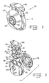
- Cord lock 10 includes a body 16 connected to or formed integrally with an extension sleeve 18.
- a plunger 20 is associated with body 16, together with a spring means 22, to releasably secure cord 12 relative to body 16.
- a back plate 24 is provided on extension sleeve 18, to secure cord lock 10 relative to article or fabric 14.
- Body 16 can be molded plastic or the like, and has a generally hollow shape, defining a pocket 30 within it.
- body 16 has a front wall 32, a back wall 34 disposed generally opposite to front wall 32 and opposed first and second side walls 36 and 38, respectively, between front wall 32 and back wall 34.
- Pocket 30 has an opening 40 thereto, disposed in an edge 42 of body 16.
- Body 16 further defines a hole 44 extending therethrough from a front face 46 of front wall 32 through front wall 32, into pocket 30, and from pocket 30 through back wall 34. The portions of hole 44 in front wall 32 and back wall 34 are in substantial axial alignment.
- Extension sleeve 18 is secured to body 16, or may be formed integrally therewith. Extension sleeve 18 projects outwardly from back wall 34 of body 16. Thus, molding of body 16 and extension sleeve 18 as a single structure from plastic or the like is suitable. Extension sleeve 18 is a cylindrical body defining a central hole 50 therethrough. Hole 50 extends entirely through extension sleeve 18 and into pocket 30. Hole 50 of extension sleeve 18 is provided substantially aligned with hole 44 of body 16. Hole 44 and hole 50 are provided spaced from edge 42, but are entirely within the area defined by pocket 30. A plurality of projections 52 are provided on the external surface of extension sleeve 18 and are adapted for attachment with back plate 24.
- Projections 52 may define a plurality of circumferential or part circumferential ridges, or may be a screw thread, or the like. As will be further explained below, back plate 24 is preferably ratchetly received on to projections 52 to accommodate articles or fabrics 14 of varying thickness.
- Plunger 20 is provided in a size and shape to fit slidably within pocket 30, relatively snuggly between front wall 32 and back wall 34, and between first and second side walls 36 and 38. Plunger 20 can move in directions inwardly and outwardly relative to opening 40 of pocket 30, generally orthogonal to aligned holes 44 and 50.
- Plunger 20 includes a plunger top 60 and a plunger body 62. Plunger body 62 slides within pocket 30, while plunger top 60 defines a cap on body 62.
- plunger top 60 is generally larger than opening 40 such that plunger top 60 cannot be pushed into pocket 30, although alternative configurations would be suitable.
- Plunger body 62 defines a plunger hole 64 extending therethrough, from a front side thereof to a back side thereof, at a position spaced from plunger top 60. Plunger body 62 is movable within pocket 30 between a first position in which plunger hole 64 is aligned with the aligned body and extension sleeve holes 44 and 50, and a second position in which plunger hole 64 is misaligned with aligned body and extension sleeve holes 44 and 50.
- Spring means or any suitable biasing device 22 is disposed in pocket 30 between a bottom (not shown) of pocket 30 and plunger body 62.
- spring means 22 is integrally formed with plunger body 62, and includes folded first and second legs 70 and 72 connected to plunger body 62 and a central foot 74 between legs 70 and 72 at ends thereof opposite body 62.
- the folded, accordion structure of legs 70 and 72 provides a spring biasing effect of plunger body 62 outwardly relative to pocket 30, toward positions in which plunger hole 64 is misaligned with aligned holes 44 and 50.
- Spring means 22 and plunger 20 can be formed integrally as a molded plastic piece.
- back plate 24 is a dome-shaped annular body defining a central opening 80 therein having an inwardly projecting ledge 82.
- Central opening 80 and ledge 82 are sized so as to allow back plate 24 to be pushed onto extension sleeve 18, with ledge 82 engaging projections 52 of extension sleeve 18.
- ledge 82 is a plurality of segments or discrete tabs 84 (see Fig. 8) forming ledge 82, and is angled in central opening 80.
- At least one of the ledge 82 and sleeve 18 is adapted to have a limited degree of flexibility such that back plate 24 can be pushed onto extension sleeve 18, with ledge 82 and/or projections 52 deflecting sufficiently so that the ledge 82 ratchets over projections 52.
- a hole or opening 90 is formed in the article or fabric 14 by punching, cutting or the like.
- Hole 90 is sufficiently large that extension sleeve 18 can be inserted therethrough; however, hole 90 should not be significantly larger than necessary to accept extension sleeve 18.
- opening 90 can be formed as a plurality of intersecting slits in article or fabric 14, allowing extension 18 to be inserted therethrough.
- Hole or opening 90 can be formed as an exit/entrance to a waistband, cuff or hood of clothing, bag opening or the like.
- extension sleeve 18 is inserted through hole 90 or slits (not shown) until a first side 92 of article or fabric 14 rests substantially against back wall 34 of body 16.
- Body 16 may be rotated such that pocket 30 faces in a suitable position for easy manipulation of plunger 20 in pocket 30.
- back plate 24 is pushed onto extension sleeve 18, with ledge 82 thereof ratcheting over projections 52 on extension sleeve 18 until back plate 24 is moved against a second side 94 of article or fabric 14.
- Article or fabric 14 is then pinched between back plate 24 and body 16 such that cord lock 10 is secured as desired relative to article or fabric 14.
- a cord lock 10 can be used on a variety of different articles or fabrics 14 of different thickness.
- Back plate 24 can be secured at several different positions along the length of extension sleeve 18, thus accommodating different articles thickness, with article or fabric 14 pinched between back plate 24 and body 16.
- cord lock 10 When secured to article or fabric 14, cord lock 10 also functions as a grommet, binding the cut edges of fabric to reduce fraying or tearing at the fabric edge.
- Plunger 20 is inserted in pocket 30 and depressed to compress spring means 22 such that plunger hole 64 is aligned with aligned holes 44 and 50.
- the size of plunger body 62 and the position of plunger hole 64 in plunger body 62 are selected such that plunger 20 can be substantially fully depressed, with plunger top 60 engaged against edge 42 when plunger hole 64 is aligned with aligned holes 44 and 50.
- cord 12 is inserted from one direction or the other such that it extends through body 16, plunger 20 and extension sleeve 18 with back plate 24 thereon. With plunger 20 depressed such that holes 64, 50 and 44 are aligned, cord 12 can be pulled in either direction, to selectively position cord 12 where desired along its length relative to cord lock 10.
- cord 12 When inward pressure on plunger 20 is released, spring means 22 urges plunger 20 outwardly relative to pocket 30, such that plunger hole 64 becomes misaligned with aligned holes 44 and 50.
- the misalignment of the holes with cord 12 extended through cord lock 10 creates a binding effect of cord 12 within body 16. Secured in this manner, cord 12 is not pulled easily in either direction relative to cord lock 10.
- plunger 20 When it becomes necessary or desirable to reposition cord 12 relative to cord lock 10, plunger 20 is depressed by applying force to plunger top 60, thereby compressing spring means 24 and realigning plunger hole 64 with aligned holes 44 and 50.
- Cord 12 can then be slid through cord lock 10 until the desired position of cord 12 relative to cord lock 10 is achieved. By again releasing plunger 20, cord 12 becomes bound within cord lock 10.
- cord lock 10 When used as the exit structure from a waistband, hood, cuff, etc. of clothing or in the hem of the opening of a bag, etc. cord lock 10 provides a smooth structure through which cord 12 can be pulled. Thus, tightening the cord is easier than if the cord must be pulled against a raw edge of material.
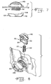
- FIGs. 5 - 9 illustrate a modified cord lock 100 that includes several different features.
- Spring means is provided as a separate coil spring 102, that can be made of metal or plastic.
- Coil spring 102 engages a post 104 on the end of plunger body 62 that first enters pocket 30.
- Spring means in the nature of coil spring 102 operates similarly to the aforedescribed structure of accordion legs 70, 72 and foot 74, to bias plunger body 62 outwardly relative to pocket 30.
- Cord lock 100 further includes a modified back plate 124 having a center ring 130 and an outwardly projecting skirt 132 from the outer edge of ring 130.
- An edge 134 of skirt 132 is a gently scalloped, thereby being non-planar.
- Relief slots 136 and 138 are provided in skirt 132, generally on opposite sides of skirt 132, thereby separating skirt 132 into substantially semi-circular portions or two-halves.
- Skirt 132 is relatively thin and flexible, yet resilient, such that the semi-circular portions thereof can deflect and bend as skirt 132 pinches fabric 14 against back wall 34, and compressing force is applied against back plate 124. As skirt 132 bends, to flatten 134, article or fabric 14 is pinched more aggressively between back plate 124 and body 16.
- central ring 130 defines a plurality of ring segments 84 for engaging projections 52 of extension sleeve 18.
- ledge 82 and projections 52 can define cooperative threads or thread segments by which a screw thread attachment is achieved.
- back wall 34 and/or back plate 24 can be provided with surface treatments such as texturing, projections or coatings to facilitate gripping article or fabric 14.
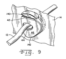
- plunger top 60 and body 16 are ergonomically shaped to facilitate grasping and pinching or squeezing, to depress plunger 20 in pocket 30.
- plunger top 60 includes a thickened edge 140 furthest from article or fabric 14, and body 16 includes an edge 142 generally opposite edge 42 that angles from front face 46 towards extension sleeve 18.
- body 16 is curved rearwardly from the portion of front face 46 defining hole 44. The generally sloping, rearwardly projecting surfaces angling towards extension sleeve 18 generally urge fingers grasping cord lock 100 to slide towards back plate 24 and article or fabric 14.
- the thumb and forefinger are less likely to slide forwardly off of front face 46 of cord lock 100 with the ergonomically advantageous shape described.
- the back plate 124 sits below the plunger top 60 when the plunger top 60 is fully depressed (see Fig. 9). In this way, especially when the article or fabric 14 is of a thin or flexible material, when the user depresses the plunger, the users thumb and/or finger will not be pinched between the plunger top 60 and back plate 124.
- the present invention provides a cord lock that can be secured or anchored to an article or fabric.
- the cord lock is more easily manipulated than cord locks loosely secured on a cord, or secured on lanyards or the like connected to the article or device.
- the present invention provides a more user friendly cord lock, and as a result of the anchoring structure, one that can be used on a variety of articles of different size and shape.
- the cord lock functions smoothly and easily.
Landscapes
- Engineering & Computer Science (AREA)
- General Engineering & Computer Science (AREA)
- Mechanical Engineering (AREA)
- Details Of Garments (AREA)
- Purses, Travelling Bags, Baskets, Or Suitcases (AREA)
- Braking Arrangements (AREA)
- Package Frames And Binding Bands (AREA)
- Slide Fasteners, Snap Fasteners, And Hook Fasteners (AREA)
- Buckles (AREA)
Applications Claiming Priority (4)
| Application Number | Priority Date | Filing Date | Title |
|---|---|---|---|
| US34571802P | 2002-01-03 | 2002-01-03 | |
| US345718P | 2002-01-03 | ||
| US302584 | 2002-11-22 | ||
| US10/302,584 US6658704B2 (en) | 2002-01-03 | 2002-11-22 | Locking device |
Publications (3)
| Publication Number | Publication Date |
|---|---|
| EP1326031A2 true EP1326031A2 (fr) | 2003-07-09 |
| EP1326031A3 EP1326031A3 (fr) | 2004-10-06 |
| EP1326031B1 EP1326031B1 (fr) | 2006-05-24 |
Family
ID=26973001
Family Applications (1)
| Application Number | Title | Priority Date | Filing Date |
|---|---|---|---|
| EP02029020A Expired - Lifetime EP1326031B1 (fr) | 2002-01-03 | 2002-12-27 | Dispositif de blocage |
Country Status (7)
| Country | Link |
|---|---|
| US (1) | US6658704B2 (fr) |
| EP (1) | EP1326031B1 (fr) |
| JP (1) | JP2003204808A (fr) |
| KR (1) | KR100925760B1 (fr) |
| DE (1) | DE60211639T2 (fr) |
| ES (1) | ES2263732T3 (fr) |
| TW (1) | TW571039B (fr) |
Cited By (2)
| Publication number | Priority date | Publication date | Assignee | Title |
|---|---|---|---|---|
| EP1325690A3 (fr) * | 2002-01-03 | 2004-11-17 | Illinois Tool Works, Inc. | Dispositif de fixation pour boucles, éléments de blocage de cordons et analogues |
| EP1653120A1 (fr) * | 2004-10-27 | 2006-05-03 | YKK Corporation | Support |
Families Citing this family (41)
| Publication number | Priority date | Publication date | Assignee | Title |
|---|---|---|---|---|
| US20040148742A1 (en) * | 2003-01-31 | 2004-08-05 | Salomon S.A. | Cord locking device and an article including such device |
| US7021509B2 (en) * | 2003-06-23 | 2006-04-04 | Shin Hui Chuang | Safety bag with firm structure |
| JP4376699B2 (ja) * | 2004-06-03 | 2009-12-02 | 株式会社ニフコ | コードロック、および、物品保持機構 |
| US7254871B2 (en) * | 2005-03-28 | 2007-08-14 | Nifco Inc. | Cord lock holder with cord lock, and structure thereof |
| USD552460S1 (en) * | 2005-07-14 | 2007-10-09 | Ykk Corporation | Cord end stopper |
| USD551066S1 (en) * | 2005-07-14 | 2007-09-18 | Ykk Corporation | Cord end stopper |
| KR100878181B1 (ko) * | 2007-08-21 | 2009-01-13 | 오성듀랄루민(주) | 눈 탐침봉의 로킹장치 |
| US9017296B2 (en) * | 2008-04-01 | 2015-04-28 | Zevex, Inc. | Safety occluder and method of use |
| US8245360B2 (en) * | 2008-09-09 | 2012-08-21 | Stafford Manufacturing Corp. | Rope grip slip-knot device |
| WO2010081295A1 (fr) * | 2009-01-15 | 2010-07-22 | Duraflex Hong Kong Limited | Dispositif de verrouillage |
| CN102281789B (zh) * | 2009-01-15 | 2013-07-31 | 香港多耐福有限公司 | 绳扣 |
| US9265294B2 (en) | 2009-05-15 | 2016-02-23 | Cohaesive Garment Technology Inc. | Methods and apparatus for affixing hardware to garments |
| US20110088230A1 (en) * | 2009-07-28 | 2011-04-21 | Warren Stevens | Barrel Nut Type Decorative Accessory and Methods For Attachment To Drawstrings |
| US8281413B2 (en) * | 2010-01-05 | 2012-10-09 | The North Face Apparel Corp. | Slip lock grommet |
| US8321999B2 (en) | 2010-07-06 | 2012-12-04 | Boden Robert O | Self-locking cord lock with housing and slide piece |
| US20140165260A1 (en) * | 2012-12-19 | 2014-06-19 | Gamal A. Harding | Shirt cuff tips and shirt cuff tip protectors |
| CN103036180B (zh) * | 2012-12-28 | 2015-12-02 | 浙江超威创元实业有限公司 | 一种绝缘线夹 |
| US20150181986A1 (en) * | 2013-12-30 | 2015-07-02 | Button International Co., Ltd. | String locking device and its female lock |
| US9795189B2 (en) | 2014-08-14 | 2017-10-24 | Thingz, Llc | Drawstring clamping device |
| USD798769S1 (en) | 2015-09-25 | 2017-10-03 | Michael T. Hodgdon | Clothing article |
| EP4006378A1 (fr) | 2016-05-31 | 2022-06-01 | NIKE Innovate C.V. | Verrouillage par corde |
| JP6659468B2 (ja) | 2016-06-06 | 2020-03-04 | 株式会社ニフコ | コードロック |
| US10527129B2 (en) * | 2016-08-26 | 2020-01-07 | Nike, Inc. | Cord lock |
| US10561936B1 (en) | 2018-04-27 | 2020-02-18 | Facebook Technologies, Llc | Lanyard and controller assembly |
| US10070700B1 (en) * | 2017-08-31 | 2018-09-11 | Oculus Vr, Llc | Lanyard adjuster |
| IT201700101149A1 (it) * | 2017-09-11 | 2019-03-11 | Metalworks S P A | Occhiello rigido multifunzione. |
| CN107912839A (zh) * | 2017-11-24 | 2018-04-17 | 嘉善县欣龙服饰辅料厂(普通合伙) | 一种具有抗电磁辐射功能的树脂绳扣及其生产工艺 |
| CN110063547B (zh) * | 2018-01-23 | 2021-07-30 | 台湾扣具工业股份有限公司 | 绳索扣 |
| GB201801759D0 (en) | 2018-02-02 | 2018-03-21 | Gripple Ltd | Clamping device |
| CN110522127A (zh) * | 2018-05-25 | 2019-12-03 | 香港多耐福有限公司 | 绳扣 |
| US11555511B2 (en) * | 2019-02-11 | 2023-01-17 | ECA Medial Instruments, Inc. | Connection system |
| US11320024B2 (en) * | 2019-06-26 | 2022-05-03 | Nite Ize, Inc. | Systems and methods for a rope, flat-strap, and bungee securing device |
| TWI717045B (zh) * | 2019-10-03 | 2021-01-21 | 振鋒企業股份有限公司 | 無線射頻辨識吊牌 |
| USD954547S1 (en) * | 2019-12-17 | 2022-06-14 | Xiao Zhang | Cord fastener |
| USD951081S1 (en) * | 2020-02-05 | 2022-05-10 | Sae Han Byul Cho | Strap length adjuster |
| US11612227B2 (en) * | 2020-02-28 | 2023-03-28 | Kiyawmi Thioub | Apparatus securable to flexible strand(s) |
| WO2021222494A1 (fr) * | 2020-04-29 | 2021-11-04 | Nike Innovate C.V. | Verrou de câble avec caractéristique de mise en prise de câble souple |
| CN113776235B (zh) * | 2021-08-24 | 2022-10-04 | 宁波富达智能科技有限公司 | 一种用于空调或除湿机的压缩机防倾倒安装结构 |
| IT202200006896A1 (it) * | 2022-04-07 | 2023-10-07 | A M F S P A | Dispositivo fermacorda, in particolare per capi di abbigliamento e simili. |
| JP1763586S (ja) * | 2022-11-21 | 2024-02-15 | 締め付けボタン | |
| TWM642601U (zh) * | 2023-03-15 | 2023-06-11 | 台灣扣具工業股份有限公司 | 繩索扣具 |
Family Cites Families (13)
| Publication number | Priority date | Publication date | Assignee | Title |
|---|---|---|---|---|
| DE1191179B (de) * | 1956-09-19 | 1965-04-15 | Carr Fastener Co Ltd | Befestigungsvorrichtung |
| GB1014489A (en) * | 1962-09-04 | 1965-12-22 | Ft Products Ltd | Improvements in and relating to fasteners |
| US4453292A (en) * | 1982-08-30 | 1984-06-12 | Illinois Tool Works Inc. | Cord lock |
| US4622723A (en) * | 1985-03-18 | 1986-11-18 | American Cord & Webbing Co., Inc. | Cord lock |
| US4811466A (en) * | 1987-03-23 | 1989-03-14 | Zubli Albert F | Releasable pull cord engagement device |
| JPS63272302A (ja) * | 1987-04-30 | 1988-11-09 | モリト株式会社 | 紐の調節固定具及びその製造方法 |
| US5197166A (en) * | 1992-05-06 | 1993-03-30 | Illinois Tool Works Inc. | Cord closure |
| JP3247020B2 (ja) * | 1994-12-26 | 2002-01-15 | ワイケイケイ株式会社 | コードストッパー |
| US5621952A (en) | 1995-09-25 | 1997-04-22 | Illinois Tool Works Inc. | Cord closure |
| JPH09140414A (ja) * | 1995-11-22 | 1997-06-03 | Nifco Inc | 紐の止め具 |
| JP3640728B2 (ja) * | 1996-03-07 | 2005-04-20 | 株式会社ニフコ | 紐止め具 |
| JPH10257907A (ja) * | 1997-03-17 | 1998-09-29 | Sukoobill Japan Kk | 衣類に固定する紐止め用具 |
| US6018851A (en) * | 1998-08-26 | 2000-02-01 | National Molding Corp. | Pre-loadable cord lock |
-
2002
- 2002-11-22 US US10/302,584 patent/US6658704B2/en not_active Expired - Lifetime
- 2002-12-27 TW TW091138215A patent/TW571039B/zh not_active IP Right Cessation
- 2002-12-27 EP EP02029020A patent/EP1326031B1/fr not_active Expired - Lifetime
- 2002-12-27 JP JP2002381762A patent/JP2003204808A/ja active Pending
- 2002-12-27 DE DE60211639T patent/DE60211639T2/de not_active Expired - Lifetime
- 2002-12-27 ES ES02029020T patent/ES2263732T3/es not_active Expired - Lifetime
- 2002-12-30 KR KR1020020086863A patent/KR100925760B1/ko not_active Expired - Fee Related
Non-Patent Citations (1)
| Title |
|---|
| None |
Cited By (3)
| Publication number | Priority date | Publication date | Assignee | Title |
|---|---|---|---|---|
| EP1325690A3 (fr) * | 2002-01-03 | 2004-11-17 | Illinois Tool Works, Inc. | Dispositif de fixation pour boucles, éléments de blocage de cordons et analogues |
| EP1653120A1 (fr) * | 2004-10-27 | 2006-05-03 | YKK Corporation | Support |
| US7257865B2 (en) | 2004-10-27 | 2007-08-21 | Ykk Corporation | Holder for cord fasteners |
Also Published As
| Publication number | Publication date |
|---|---|
| DE60211639T2 (de) | 2006-10-26 |
| TW200301804A (en) | 2003-07-16 |
| TW571039B (en) | 2004-01-11 |
| KR20030060060A (ko) | 2003-07-12 |
| ES2263732T3 (es) | 2006-12-16 |
| DE60211639D1 (de) | 2006-06-29 |
| JP2003204808A (ja) | 2003-07-22 |
| KR100925760B1 (ko) | 2009-11-11 |
| US6658704B2 (en) | 2003-12-09 |
| EP1326031A3 (fr) | 2004-10-06 |
| US20030121126A1 (en) | 2003-07-03 |
| EP1326031B1 (fr) | 2006-05-24 |
Similar Documents
| Publication | Publication Date | Title |
|---|---|---|
| US6658704B2 (en) | Locking device | |
| JP3165024U (ja) | コードロック組立体 | |
| US8281413B2 (en) | Slip lock grommet | |
| US5577306A (en) | Friction based one-handed closure and release mechanism | |
| US5195218A (en) | Flexible cord lock device | |
| CA1324357C (fr) | Mecanisme de fermeture | |
| EP0775845B1 (fr) | Dispositif externe de fermeture et d'ouverture manipulable d'une seule main | |
| EP1811874A2 (fr) | Ensemble tirette de fermeture recouvert | |
| CN1256053C (zh) | 锁定件 | |
| US20200138150A1 (en) | A fastening system | |
| US20140345092A1 (en) | Nested zipper puller | |
| JP3377967B2 (ja) | 紐用ストッパー | |
| JP2005206969A (ja) | 絞り機構付き製品 | |
| WO2019067003A1 (fr) | Attache de cordon à verrouillage libérable | |
| WO2013109596A1 (fr) | Verrou coulissant tel qu'un verrou de câble | |
| HK1181272B (en) | Slip lock grommet |
Legal Events
| Date | Code | Title | Description |
|---|---|---|---|
| PUAI | Public reference made under article 153(3) epc to a published international application that has entered the european phase |
Free format text: ORIGINAL CODE: 0009012 |
|
| AK | Designated contracting states |
Designated state(s): AT BE BG CH CY CZ DE DK EE ES FI FR GB GR IE IT LI LU MC NL PT SE SI SK TR |
|
| AX | Request for extension of the european patent |
Extension state: AL LT LV MK RO |
|
| PUAL | Search report despatched |
Free format text: ORIGINAL CODE: 0009013 |
|
| AK | Designated contracting states |
Kind code of ref document: A3 Designated state(s): AT BE BG CH CY CZ DE DK EE ES FI FR GB GR IE IT LI LU MC NL PT SE SI SK TR |
|
| AX | Request for extension of the european patent |
Extension state: AL LT LV MK RO |
|
| 17P | Request for examination filed |
Effective date: 20050211 |
|
| 17Q | First examination report despatched |
Effective date: 20050426 |
|
| AKX | Designation fees paid |
Designated state(s): DE ES FR GB IT |
|
| GRAP | Despatch of communication of intention to grant a patent |
Free format text: ORIGINAL CODE: EPIDOSNIGR1 |
|
| GRAS | Grant fee paid |
Free format text: ORIGINAL CODE: EPIDOSNIGR3 |
|
| GRAA | (expected) grant |
Free format text: ORIGINAL CODE: 0009210 |
|
| AK | Designated contracting states |
Kind code of ref document: B1 Designated state(s): DE ES FR GB IT |
|
| REG | Reference to a national code |
Ref country code: GB Ref legal event code: FG4D |
|
| REF | Corresponds to: |
Ref document number: 60211639 Country of ref document: DE Date of ref document: 20060629 Kind code of ref document: P |
|
| REG | Reference to a national code |
Ref country code: ES Ref legal event code: FG2A Ref document number: 2263732 Country of ref document: ES Kind code of ref document: T3 |
|
| ET | Fr: translation filed | ||
| PLBE | No opposition filed within time limit |
Free format text: ORIGINAL CODE: 0009261 |
|
| STAA | Information on the status of an ep patent application or granted ep patent |
Free format text: STATUS: NO OPPOSITION FILED WITHIN TIME LIMIT |
|
| 26N | No opposition filed |
Effective date: 20070227 |
|
| PGFP | Annual fee paid to national office [announced via postgrant information from national office to epo] |
Ref country code: IT Payment date: 20101223 Year of fee payment: 9 |
|
| PGFP | Annual fee paid to national office [announced via postgrant information from national office to epo] |
Ref country code: FR Payment date: 20130110 Year of fee payment: 11 |
|
| PGFP | Annual fee paid to national office [announced via postgrant information from national office to epo] |
Ref country code: DE Payment date: 20121231 Year of fee payment: 11 |
|
| PG25 | Lapsed in a contracting state [announced via postgrant information from national office to epo] |
Ref country code: IT Free format text: LAPSE BECAUSE OF NON-PAYMENT OF DUE FEES Effective date: 20121227 |
|
| PGFP | Annual fee paid to national office [announced via postgrant information from national office to epo] |
Ref country code: GB Payment date: 20131227 Year of fee payment: 12 |
|
| REG | Reference to a national code |
Ref country code: DE Ref legal event code: R119 Ref document number: 60211639 Country of ref document: DE |
|
| REG | Reference to a national code |
Ref country code: FR Ref legal event code: ST Effective date: 20140829 |
|
| REG | Reference to a national code |
Ref country code: DE Ref legal event code: R119 Ref document number: 60211639 Country of ref document: DE Effective date: 20140701 |
|
| PG25 | Lapsed in a contracting state [announced via postgrant information from national office to epo] |
Ref country code: DE Free format text: LAPSE BECAUSE OF NON-PAYMENT OF DUE FEES Effective date: 20140701 |
|
| PG25 | Lapsed in a contracting state [announced via postgrant information from national office to epo] |
Ref country code: FR Free format text: LAPSE BECAUSE OF NON-PAYMENT OF DUE FEES Effective date: 20131231 |
|
| GBPC | Gb: european patent ceased through non-payment of renewal fee |
Effective date: 20141227 |
|
| PG25 | Lapsed in a contracting state [announced via postgrant information from national office to epo] |
Ref country code: GB Free format text: LAPSE BECAUSE OF NON-PAYMENT OF DUE FEES Effective date: 20141227 |
|
| PGFP | Annual fee paid to national office [announced via postgrant information from national office to epo] |
Ref country code: ES Payment date: 20200102 Year of fee payment: 18 |
|
| REG | Reference to a national code |
Ref country code: ES Ref legal event code: FD2A Effective date: 20220406 |
|
| PG25 | Lapsed in a contracting state [announced via postgrant information from national office to epo] |
Ref country code: ES Free format text: LAPSE BECAUSE OF NON-PAYMENT OF DUE FEES Effective date: 20201228 |