EP1326039A1 - Rückschlagventil mit überdimensionierten Lippen - Google Patents
Rückschlagventil mit überdimensionierten Lippen Download PDFInfo
- Publication number
- EP1326039A1 EP1326039A1 EP20020075037 EP02075037A EP1326039A1 EP 1326039 A1 EP1326039 A1 EP 1326039A1 EP 20020075037 EP20020075037 EP 20020075037 EP 02075037 A EP02075037 A EP 02075037A EP 1326039 A1 EP1326039 A1 EP 1326039A1
- Authority
- EP
- European Patent Office
- Prior art keywords
- check valve
- upstream inlet
- downstream outlet
- inlet part
- outlet part
- Prior art date
- Legal status (The legal status is an assumption and is not a legal conclusion. Google has not performed a legal analysis and makes no representation as to the accuracy of the status listed.)
- Granted
Links
- 238000011144 upstream manufacturing Methods 0.000 claims abstract description 28
- 239000012530 fluid Substances 0.000 claims abstract description 10
- 230000007704 transition Effects 0.000 claims abstract 6
- 230000002787 reinforcement Effects 0.000 claims description 10
- 239000000463 material Substances 0.000 claims description 5
- 229920000728 polyester Polymers 0.000 claims description 5
- 239000004744 fabric Substances 0.000 claims description 4
- 238000000034 method Methods 0.000 claims description 2
- 239000013536 elastomeric material Substances 0.000 claims 6
- 241000405070 Percophidae Species 0.000 description 23
- 229920001971 elastomer Polymers 0.000 description 3
- XLYOFNOQVPJJNP-UHFFFAOYSA-N water Substances O XLYOFNOQVPJJNP-UHFFFAOYSA-N 0.000 description 3
- 238000010276 construction Methods 0.000 description 2
- 238000013461 design Methods 0.000 description 2
- 239000000806 elastomer Substances 0.000 description 2
- 238000004519 manufacturing process Methods 0.000 description 2
- 239000004677 Nylon Substances 0.000 description 1
- 239000002174 Styrene-butadiene Substances 0.000 description 1
- 238000013459 approach Methods 0.000 description 1
- MTAZNLWOLGHBHU-UHFFFAOYSA-N butadiene-styrene rubber Chemical compound C=CC=C.C=CC1=CC=CC=C1 MTAZNLWOLGHBHU-UHFFFAOYSA-N 0.000 description 1
- 230000007423 decrease Effects 0.000 description 1
- 239000007788 liquid Substances 0.000 description 1
- 238000012986 modification Methods 0.000 description 1
- 230000004048 modification Effects 0.000 description 1
- 229920001778 nylon Polymers 0.000 description 1
- 229920001084 poly(chloroprene) Polymers 0.000 description 1
- 230000003014 reinforcing effect Effects 0.000 description 1
- 238000011160 research Methods 0.000 description 1
- 239000005060 rubber Substances 0.000 description 1
- 239000011115 styrene butadiene Substances 0.000 description 1
- 229920003048 styrene butadiene rubber Polymers 0.000 description 1
- 229920002994 synthetic fiber Polymers 0.000 description 1
- 238000012360 testing method Methods 0.000 description 1
Images

Classifications
-
- F—MECHANICAL ENGINEERING; LIGHTING; HEATING; WEAPONS; BLASTING
- F16—ENGINEERING ELEMENTS AND UNITS; GENERAL MEASURES FOR PRODUCING AND MAINTAINING EFFECTIVE FUNCTIONING OF MACHINES OR INSTALLATIONS; THERMAL INSULATION IN GENERAL
- F16K—VALVES; TAPS; COCKS; ACTUATING-FLOATS; DEVICES FOR VENTING OR AERATING
- F16K15/00—Check valves
- F16K15/14—Check valves with flexible valve members
- F16K15/144—Check valves with flexible valve members the closure elements being fixed along all or a part of their periphery
- F16K15/147—Check valves with flexible valve members the closure elements being fixed along all or a part of their periphery the closure elements having specially formed slits or being of an elongated easily collapsible form
-
- Y—GENERAL TAGGING OF NEW TECHNOLOGICAL DEVELOPMENTS; GENERAL TAGGING OF CROSS-SECTIONAL TECHNOLOGIES SPANNING OVER SEVERAL SECTIONS OF THE IPC; TECHNICAL SUBJECTS COVERED BY FORMER USPC CROSS-REFERENCE ART COLLECTIONS [XRACs] AND DIGESTS
- Y10—TECHNICAL SUBJECTS COVERED BY FORMER USPC
- Y10T—TECHNICAL SUBJECTS COVERED BY FORMER US CLASSIFICATION
- Y10T137/00—Fluid handling
- Y10T137/7722—Line condition change responsive valves
- Y10T137/7837—Direct response valves [i.e., check valve type]
- Y10T137/7879—Resilient material valve
- Y10T137/788—Having expansible port
- Y10T137/7882—Having exit lip
-
- Y—GENERAL TAGGING OF NEW TECHNOLOGICAL DEVELOPMENTS; GENERAL TAGGING OF CROSS-SECTIONAL TECHNOLOGIES SPANNING OVER SEVERAL SECTIONS OF THE IPC; TECHNICAL SUBJECTS COVERED BY FORMER USPC CROSS-REFERENCE ART COLLECTIONS [XRACs] AND DIGESTS
- Y10—TECHNICAL SUBJECTS COVERED BY FORMER USPC
- Y10T—TECHNICAL SUBJECTS COVERED BY FORMER US CLASSIFICATION
- Y10T137/00—Fluid handling
- Y10T137/7722—Line condition change responsive valves
- Y10T137/7837—Direct response valves [i.e., check valve type]
- Y10T137/7879—Resilient material valve
- Y10T137/788—Having expansible port
- Y10T137/7882—Having exit lip
- Y10T137/7883—With biasing means
-
- Y—GENERAL TAGGING OF NEW TECHNOLOGICAL DEVELOPMENTS; GENERAL TAGGING OF CROSS-SECTIONAL TECHNOLOGIES SPANNING OVER SEVERAL SECTIONS OF THE IPC; TECHNICAL SUBJECTS COVERED BY FORMER USPC CROSS-REFERENCE ART COLLECTIONS [XRACs] AND DIGESTS
- Y10—TECHNICAL SUBJECTS COVERED BY FORMER USPC
- Y10T—TECHNICAL SUBJECTS COVERED BY FORMER US CLASSIFICATION
- Y10T137/00—Fluid handling
- Y10T137/7722—Line condition change responsive valves
- Y10T137/7837—Direct response valves [i.e., check valve type]
- Y10T137/7879—Resilient material valve
- Y10T137/788—Having expansible port
- Y10T137/7882—Having exit lip
- Y10T137/7886—Internally extending mount
Definitions
- the present invention relates to a check valve of the so-called "duckbill" type for use in drainage systems and effluent outfall lines.
- a check valve is essentially a valve which allows fluid to flow in only one direction through a conduit, while closing and preventing back or reverse flow, when back pressure builds up downstream of the valve to a level greater than the upstream fluid pressure head.
- Check valves are used in various fluid transportation operations and must include some means of allowing the forward flow of liquid yet preventing any backflow.
- Conventional rubber duckbill check valves have an inlet cuff, an outlet bill and a transitional middle part for connecting the cuff and the bill.
- the bill comprises a slit which opens when fluid is forced through the valve.
- existing "duckbill" type check valves have a bill slit dimension that is equal to or less than one-half the cuff (inlet) circumference. The reason for this is that if the bill slit dimension is larger than one-half the circumference of the cuff diameter, it becomes difficult or even impossible to remove a one-piece mandrel, which is used to manufacture the check valve through the cuff.
- valves In most applications, it is desirable to have the maximum flow through the valve at the lowest possible pressure drop in the forward direction of the flow or, in other words, the lowest possible headloss.
- valves have been recently developed in which the width of the bill is larger than the diameter of the cuff. The output area and the open position of the bill thus approaches more of the inlet area of the cuff, and the headloss decreases.
- U.S. Patent No. 5,931,197 to Raftis et al. discloses an asymmetrical check valve of this type.
- the present invention is a check valve with an oversized bill.
- the present invention includes a tubular inlet part, an outlet part and a transitional middle part, connecting the inlet part with the outlet part, wherein the width or height of the outlet part is at least approximately 1.57 times the diameter of the inlet part.
- the outlet part may be symmetrical about a longitudinal plane through the check valve. It can also have a curved bill.
- valve of this size is the low headloss compared to conventional duckbill check valves. With an effective outlet area larger than the inlet area of the valve, the headloss will drop below the headloss of an open pipe end at high flow rates.
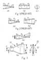
- Figs. 1 and 2 both show conventional duckbill check valves. These valves comprise an inlet portion 10, a transitional portion 12 and an outlet portion 14. The advantages of these designs are the low tooling costs and simple removal of a mandrel from the completed part.
- the check valve shown in Fig. 2 is slightly widening, with the width of the outlet portion 14 approximately equal to one-half the circumference of the inlet portion 10. The mandrel is slightly more difficult to remove from the completed valve, but the headless is lower.
- the headloss is inversely proportional to the discharge area squared.
- the present invention is a duckbill check valve 22 with an enlarged bill, as shown in Fig. 3.
- the duckbill check valve 22 comprises an inlet part 16, a transitional part 18 and an outlet part 20, which appears as a pair of lips facing and engaging one another.
- the height h of the outlet part 20 (or bill) of Fig. 3 is substantially larger than the diameter d of the inlet part 16. In fact, the height of the outlet part 20, in its closed position, should be at least approximately 1.57 times the diameter d of the inlet part 16.
- the outlet part 20 may be oriented in different positions, rotatable about an axis perpendicular to the pipeline 30.
- Fig. 3 shows the outlet part 20 of the present invention wherein the outlet part 20 (or lips) is oriented in a vertical manner, making the height h the operative dimension.
- Figs. 4-7 the outlet part 20 is oriented in a horizontal manner, making the width w the operative dimension. According to the invention, it is the longitudinal dimension of the outlet part, in its closed position, that must be substantially larger than the diameter d of the inlet part 16.
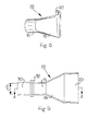
- Figs. 4-7 show the different opening stages of a duckbill check valve 22 according to the present invention.
- Fig. 4 shows a closed duckbill check valve 22
- Figs. 5 and 6 show a progressively open duckbill check valve 22
- Fig. 7 shows a fully open duckbill check valve 22.
- the outlet part 20 will not open to a full circular opening, but will open to approximately 40% to 85% of the area of a full circular opening.
- Valves built in accordance with the present invention with an outlet part 20 bill slit greater than 1.57 times the inlet part 16 bore diameter, will have an open area about equal to, or larger than, the area of the inlet part 16.
- the headloss is considerably lower than the headloss of conventional valves. Again, it is the width w of the outlet part 20 (in Figs. 4-8) that should be at least approximately 1.57 times the diameter d of the inlet part.
- the duckbill check valve 22 is preferably made from an elastomer, such as neoprene, or an elastomer reinforced with synthetic fabric, such as nylon or polyester, with construction similar to an automobile tire.
- the inlet part 16 is generally made of a stiff, durable material, such as styrene butadiene, with polyester fabric reinforcing, whereas the outlet part 20 is made of a flexible material to allow proper opening and closing of the outlet part 20.
- the outlet part 20 may be symmetrical about a longitudinal plane A-A through the duckbill check valve 22. This longitudinal plane A-A is coincident with a center line of the inlet part 16.
- the outlet part 20 may be curvilinear, as described in U.S. Patent No. 5,727,593.
- the inlet part 16 may be fitted with a flange 32, instead of the cuff shown in the drawings.
- a duckbill check valve according to the preferred embodiment is manufactured similarly to a tire, using a multiple-piece mandrel.
- the mandrel will have to be disassembled to remove it from the inside of the valve.
- the great reduction in headloss will justify the added expense of manufacturing the invention.
- the duckbill check valve 22 can be provided with local reinforcements, such as embedded wire, plates, rings and tubes.
Landscapes
- Engineering & Computer Science (AREA)
- General Engineering & Computer Science (AREA)
- Mechanical Engineering (AREA)
- Check Valves (AREA)
Priority Applications (4)
| Application Number | Priority Date | Filing Date | Title |
|---|---|---|---|
| US09/533,298 US6367505B1 (en) | 2000-03-22 | 2000-03-22 | Check valve with oversized bill |
| EP02075037A EP1326039B1 (de) | 2000-03-22 | 2002-01-04 | Rückschlagventil mit überdimensionierten Lippen |
| CA002366605A CA2366605C (en) | 2000-03-22 | 2002-01-04 | Check valve with oversized bill |
| CNB021025800A CN1288370C (zh) | 2000-03-22 | 2002-01-07 | 具有大尺寸出口嘴的止回阀 |
Applications Claiming Priority (4)
| Application Number | Priority Date | Filing Date | Title |
|---|---|---|---|
| US09/533,298 US6367505B1 (en) | 2000-03-22 | 2000-03-22 | Check valve with oversized bill |
| EP02075037A EP1326039B1 (de) | 2000-03-22 | 2002-01-04 | Rückschlagventil mit überdimensionierten Lippen |
| CA002366605A CA2366605C (en) | 2000-03-22 | 2002-01-04 | Check valve with oversized bill |
| CNB021025800A CN1288370C (zh) | 2000-03-22 | 2002-01-07 | 具有大尺寸出口嘴的止回阀 |
Publications (2)
| Publication Number | Publication Date |
|---|---|
| EP1326039A1 true EP1326039A1 (de) | 2003-07-09 |
| EP1326039B1 EP1326039B1 (de) | 2007-05-23 |
Family
ID=32110865
Family Applications (1)
| Application Number | Title | Priority Date | Filing Date |
|---|---|---|---|
| EP02075037A Expired - Lifetime EP1326039B1 (de) | 2000-03-22 | 2002-01-04 | Rückschlagventil mit überdimensionierten Lippen |
Country Status (4)
| Country | Link |
|---|---|
| US (1) | US6367505B1 (de) |
| EP (1) | EP1326039B1 (de) |
| CN (1) | CN1288370C (de) |
| CA (1) | CA2366605C (de) |
Cited By (2)
| Publication number | Priority date | Publication date | Assignee | Title |
|---|---|---|---|---|
| DE102008007748A1 (de) * | 2008-02-05 | 2009-08-06 | Evac Gmbh | Ventilanordnung für gravitätische Flüssigkeitsabfuhr mit der Über- und Unterdruckphase |
| DE202012000838U1 (de) * | 2012-01-30 | 2013-05-02 | Evac Gmbh | Ventil für die Abfuhr eines flüssigen Mediums aus einem gegenüber einer Umgebung druckgedämpften Raum |
Families Citing this family (21)
| Publication number | Priority date | Publication date | Assignee | Title |
|---|---|---|---|---|
| US6719004B2 (en) | 2001-06-19 | 2004-04-13 | Donald G. Huber | Check valve floor drain |
| FR2841529B1 (fr) * | 2002-06-28 | 2004-07-30 | Thales Sa | Ancre flottante autoadaptative et procede d'utilisation |
| US6953059B2 (en) * | 2002-07-29 | 2005-10-11 | Red Valve Company, Inc. | Check valve with hanger |
| EP1559938A1 (de) | 2004-01-27 | 2005-08-03 | Red Valve Company, Inc. | Rückschlagventil mit Aufhängeteil |
| WO2006105574A1 (en) * | 2004-10-11 | 2006-10-12 | Sophinity Pty Ltd | Dispensing fluids from containers using self closing valve, typically duckbill type valve |
| US20080171988A1 (en) * | 2007-01-17 | 2008-07-17 | Erblan Surgical, Inc. | Double-cone sphincter introducer assembly and integrated valve assembly |
| US20110017330A1 (en) * | 2008-02-06 | 2011-01-27 | Vincenzo Di Leo | Maximum pressure hydraulic valve |
| CA2684248C (en) | 2009-11-02 | 2014-12-09 | Elasto-Valve Rubber Products, Inc. | I-beam check valve |
| US9139991B2 (en) | 2011-01-31 | 2015-09-22 | The Rectorseal Corporation | Floor drain valve with resiliently mounted rigid flappers |
| US10316977B2 (en) | 2011-03-01 | 2019-06-11 | Red Valve Company, Inc. | Multi-outlet check valve nozzle |
| WO2013096967A1 (en) * | 2011-12-22 | 2013-06-27 | Flsmidth A/S | Variable flow self-diluting feedwell system |
| US9347574B1 (en) * | 2012-04-04 | 2016-05-24 | Taylo Innovations LLC | Self actuating weather protective cover |
| US20140175020A1 (en) * | 2012-12-26 | 2014-06-26 | Flsmidth A/S | Variable flow self-diluting feedwell system |
| US8978693B2 (en) | 2013-01-28 | 2015-03-17 | Windcatcher Technology LLC | Inflation valve allowing for rapid inflation and deflation of an inflatable object |
| US9416986B2 (en) | 2013-06-24 | 2016-08-16 | The Rectorseal Corporation | Valve for roof vent |
| US9010363B2 (en) | 2013-06-24 | 2015-04-21 | The Rectorseal Corporation | Drain valve |
| US9556964B2 (en) | 2014-04-22 | 2017-01-31 | Nws Europa Gmbh | Gravity drain valve |
| CN105944457A (zh) * | 2016-07-21 | 2016-09-21 | 厦门理工学院 | 一种真空吸污车自排水的气水分离器 |
| CA3148088A1 (en) * | 2019-07-24 | 2021-01-28 | Quest Medical, Inc. | Filtered vacuum relief vent valve |
| US11092254B1 (en) * | 2020-03-26 | 2021-08-17 | Jose Luis Rueda Calvet | Self-sealing valve for an inflatable body and method for manufacturing same |
| CN116221492A (zh) * | 2022-12-16 | 2023-06-06 | 中霖中科环境科技(安徽)股份有限公司 | 鸭嘴止回阀 |
Citations (4)
| Publication number | Priority date | Publication date | Assignee | Title |
|---|---|---|---|---|
| GB602102A (en) * | 1943-10-04 | 1948-05-20 | Paul Georges Elie Jean Uchard | Improvements in and relating to flap valves |
| US4494575A (en) * | 1982-02-13 | 1985-01-22 | Coopers Filters Limited | Gravity dump valve |
| US5727593A (en) * | 1996-06-26 | 1998-03-17 | Red Valve Company, Inc. | Tide gate valve with curvilinear bill |
| US5897828A (en) * | 1994-08-15 | 1999-04-27 | Whitbread, Plc | Method and apparatus for the manufacture of duckbill valves |
Family Cites Families (4)
| Publication number | Priority date | Publication date | Assignee | Title |
|---|---|---|---|---|
| US4585031A (en) * | 1985-07-12 | 1986-04-29 | Red Valve Co., Inc. | Inversion-resistant tide gate valve |
| US4607663A (en) * | 1985-07-12 | 1986-08-26 | Red Valve Co., Inc. | Inversion-resistant, readily-openable tide gate valve |
| US5606995A (en) * | 1994-10-26 | 1997-03-04 | Red Valve Company, Inc. | Inversion-resistant, readily openable tide gate valve |
| US5931197A (en) | 1997-09-22 | 1999-08-03 | Red Valve Co., Inc. | Asymmetrical check valve |
-
2000
- 2000-03-22 US US09/533,298 patent/US6367505B1/en not_active Expired - Lifetime
-
2002
- 2002-01-04 CA CA002366605A patent/CA2366605C/en not_active Expired - Lifetime
- 2002-01-04 EP EP02075037A patent/EP1326039B1/de not_active Expired - Lifetime
- 2002-01-07 CN CNB021025800A patent/CN1288370C/zh not_active Expired - Lifetime
Patent Citations (4)
| Publication number | Priority date | Publication date | Assignee | Title |
|---|---|---|---|---|
| GB602102A (en) * | 1943-10-04 | 1948-05-20 | Paul Georges Elie Jean Uchard | Improvements in and relating to flap valves |
| US4494575A (en) * | 1982-02-13 | 1985-01-22 | Coopers Filters Limited | Gravity dump valve |
| US5897828A (en) * | 1994-08-15 | 1999-04-27 | Whitbread, Plc | Method and apparatus for the manufacture of duckbill valves |
| US5727593A (en) * | 1996-06-26 | 1998-03-17 | Red Valve Company, Inc. | Tide gate valve with curvilinear bill |
Cited By (2)
| Publication number | Priority date | Publication date | Assignee | Title |
|---|---|---|---|---|
| DE102008007748A1 (de) * | 2008-02-05 | 2009-08-06 | Evac Gmbh | Ventilanordnung für gravitätische Flüssigkeitsabfuhr mit der Über- und Unterdruckphase |
| DE202012000838U1 (de) * | 2012-01-30 | 2013-05-02 | Evac Gmbh | Ventil für die Abfuhr eines flüssigen Mediums aus einem gegenüber einer Umgebung druckgedämpften Raum |
Also Published As
| Publication number | Publication date |
|---|---|
| CN1288370C (zh) | 2006-12-06 |
| US6367505B1 (en) | 2002-04-09 |
| CA2366605A1 (en) | 2003-07-04 |
| CA2366605C (en) | 2004-10-12 |
| CN1432751A (zh) | 2003-07-30 |
| EP1326039B1 (de) | 2007-05-23 |
Similar Documents
| Publication | Publication Date | Title |
|---|---|---|
| US6367505B1 (en) | Check valve with oversized bill | |
| US6585005B1 (en) | Reinforced tide gate valve | |
| US7445028B1 (en) | Check valves | |
| US6412514B1 (en) | Flip check valve | |
| US4492253A (en) | Tide gate valve | |
| US5769125A (en) | Inversion-resistant, readily openable tide gate valve | |
| US5727593A (en) | Tide gate valve with curvilinear bill | |
| NZ516540A (en) | A non-return valve | |
| US4585031A (en) | Inversion-resistant tide gate valve | |
| US5606995A (en) | Inversion-resistant, readily openable tide gate valve | |
| US5931197A (en) | Asymmetrical check valve | |
| AU2017300752B2 (en) | Elastomeric in-line tide gate valve | |
| EP1588083B1 (de) | Rückflussverhinderer | |
| JP5406694B2 (ja) | 螺旋案内路付き縦管 | |
| US6953059B2 (en) | Check valve with hanger | |
| AU2023356723B2 (en) | Check valve with secondary flap | |
| GB2346198A (en) | Non-return device | |
| AU1004902A (en) | Check valve with oversized bill | |
| US20050274415A1 (en) | Multiple valve drain and pipe-cleaning device | |
| US20010023705A1 (en) | Backflow valve for an end of a pipe | |
| CA3269456C (en) | Check valve with secondary flap | |
| DE60112784T2 (de) | Rückschlagventil mit einem ballförmigen ventilkörper | |
| US20260132859A1 (en) | Check Valve With Secondary Flap | |
| HK1055783A1 (zh) | 具有大尺寸出口嘴的止回阀 | |
| HK1055783B (zh) | 具有大尺寸出口嘴的止回閥 |
Legal Events
| Date | Code | Title | Description |
|---|---|---|---|
| PUAI | Public reference made under article 153(3) epc to a published international application that has entered the european phase |
Free format text: ORIGINAL CODE: 0009012 |
|
| AK | Designated contracting states |
Designated state(s): AT BE CH CY DE DK ES FI FR GB GR IE IT LI LU MC NL PT SE TR |
|
| AX | Request for extension of the european patent |
Extension state: AL LT LV MK RO SI |
|
| 17P | Request for examination filed |
Effective date: 20040109 |
|
| AKX | Designation fees paid |
Designated state(s): ES GB IE |
|
| REG | Reference to a national code |
Ref country code: DE Ref legal event code: 8566 |
|
| 17Q | First examination report despatched |
Effective date: 20040921 |
|
| GRAP | Despatch of communication of intention to grant a patent |
Free format text: ORIGINAL CODE: EPIDOSNIGR1 |
|
| GRAS | Grant fee paid |
Free format text: ORIGINAL CODE: EPIDOSNIGR3 |
|
| GRAA | (expected) grant |
Free format text: ORIGINAL CODE: 0009210 |
|
| AK | Designated contracting states |
Kind code of ref document: B1 Designated state(s): ES GB IE |
|
| REG | Reference to a national code |
Ref country code: GB Ref legal event code: FG4D |
|
| REG | Reference to a national code |
Ref country code: IE Ref legal event code: FG4D |
|
| PG25 | Lapsed in a contracting state [announced via postgrant information from national office to epo] |
Ref country code: ES Free format text: LAPSE BECAUSE OF FAILURE TO SUBMIT A TRANSLATION OF THE DESCRIPTION OR TO PAY THE FEE WITHIN THE PRESCRIBED TIME-LIMIT Effective date: 20070903 |
|
| PLBE | No opposition filed within time limit |
Free format text: ORIGINAL CODE: 0009261 |
|
| STAA | Information on the status of an ep patent application or granted ep patent |
Free format text: STATUS: NO OPPOSITION FILED WITHIN TIME LIMIT |
|
| 26N | No opposition filed |
Effective date: 20080226 |
|
| PGFP | Annual fee paid to national office [announced via postgrant information from national office to epo] |
Ref country code: IE Payment date: 20080111 Year of fee payment: 7 |
|
| PG25 | Lapsed in a contracting state [announced via postgrant information from national office to epo] |
Ref country code: IE Free format text: LAPSE BECAUSE OF NON-PAYMENT OF DUE FEES Effective date: 20090105 |
|
| PGFP | Annual fee paid to national office [announced via postgrant information from national office to epo] |
Ref country code: GB Payment date: 20151230 Year of fee payment: 15 |
|
| GBPC | Gb: european patent ceased through non-payment of renewal fee |
Effective date: 20170104 |
|
| PG25 | Lapsed in a contracting state [announced via postgrant information from national office to epo] |
Ref country code: GB Free format text: LAPSE BECAUSE OF NON-PAYMENT OF DUE FEES Effective date: 20170104 |