EP1326084B1 - Méthode pour la détection de la condition des batteries - Google Patents
Méthode pour la détection de la condition des batteries Download PDFInfo
- Publication number
- EP1326084B1 EP1326084B1 EP02090423A EP02090423A EP1326084B1 EP 1326084 B1 EP1326084 B1 EP 1326084B1 EP 02090423 A EP02090423 A EP 02090423A EP 02090423 A EP02090423 A EP 02090423A EP 1326084 B1 EP1326084 B1 EP 1326084B1
- Authority
- EP
- European Patent Office
- Prior art keywords
- battery
- time
- discharge
- load
- voltage
- Prior art date
- Legal status (The legal status is an assumption and is not a legal conclusion. Google has not performed a legal analysis and makes no representation as to the accuracy of the status listed.)
- Expired - Lifetime
Links
Images


Classifications
-
- G—PHYSICS
- G01—MEASURING; TESTING
- G01R—MEASURING ELECTRIC VARIABLES; MEASURING MAGNETIC VARIABLES
- G01R19/00—Arrangements for measuring currents or voltages or for indicating presence or sign thereof
- G01R19/165—Indicating that current or voltage is either above or below a predetermined value or within or outside a predetermined range of values
- G01R19/16533—Indicating that current or voltage is either above or below a predetermined value or within or outside a predetermined range of values characterised by the application
- G01R19/16538—Indicating that current or voltage is either above or below a predetermined value or within or outside a predetermined range of values characterised by the application in AC or DC supplies
- G01R19/16542—Indicating that current or voltage is either above or below a predetermined value or within or outside a predetermined range of values characterised by the application in AC or DC supplies for batteries
-
- G—PHYSICS
- G01—MEASURING; TESTING
- G01R—MEASURING ELECTRIC VARIABLES; MEASURING MAGNETIC VARIABLES
- G01R31/00—Arrangements for testing electric properties; Arrangements for locating electric faults; Arrangements for electrical testing characterised by what is being tested not provided for elsewhere
- G01R31/36—Arrangements for testing, measuring or monitoring the electrical condition of accumulators or electric batteries, e.g. capacity or state of charge [SoC]
- G01R31/385—Arrangements for measuring battery or accumulator variables
- G01R31/387—Determining ampere-hour charge capacity or SoC
- G01R31/388—Determining ampere-hour charge capacity or SoC involving voltage measurements
-
- H—ELECTRICITY
- H01—ELECTRIC ELEMENTS
- H01M—PROCESSES OR MEANS, e.g. BATTERIES, FOR THE DIRECT CONVERSION OF CHEMICAL ENERGY INTO ELECTRICAL ENERGY
- H01M10/00—Secondary cells; Manufacture thereof
- H01M10/42—Methods or arrangements for servicing or maintenance of secondary cells or secondary half-cells
- H01M10/44—Methods for charging or discharging
- H01M10/441—Methods for charging or discharging for several batteries or cells simultaneously or sequentially
-
- H—ELECTRICITY
- H01—ELECTRIC ELEMENTS
- H01M—PROCESSES OR MEANS, e.g. BATTERIES, FOR THE DIRECT CONVERSION OF CHEMICAL ENERGY INTO ELECTRICAL ENERGY
- H01M10/00—Secondary cells; Manufacture thereof
- H01M10/42—Methods or arrangements for servicing or maintenance of secondary cells or secondary half-cells
- H01M10/48—Accumulators combined with arrangements for measuring, testing or indicating the condition of cells, e.g. the level or density of the electrolyte
- H01M10/482—Accumulators combined with arrangements for measuring, testing or indicating the condition of cells, e.g. the level or density of the electrolyte for several batteries or cells simultaneously or sequentially
-
- H—ELECTRICITY
- H02—GENERATION; CONVERSION OR DISTRIBUTION OF ELECTRIC POWER
- H02J—ELECTRIC POWER NETWORKS; CIRCUIT ARRANGEMENTS OR SYSTEMS FOR SUPPLYING OR DISTRIBUTING ELECTRIC POWER; SYSTEMS FOR STORING ELECTRIC ENERGY
- H02J7/00—Circuit arrangements for charging or discharging batteries or for supplying loads from batteries
- H02J7/50—Circuit arrangements for charging or discharging batteries or for supplying loads from batteries acting upon multiple batteries simultaneously or sequentially
-
- H—ELECTRICITY
- H02—GENERATION; CONVERSION OR DISTRIBUTION OF ELECTRIC POWER
- H02J—ELECTRIC POWER NETWORKS; CIRCUIT ARRANGEMENTS OR SYSTEMS FOR SUPPLYING OR DISTRIBUTING ELECTRIC POWER; SYSTEMS FOR STORING ELECTRIC ENERGY
- H02J7/00—Circuit arrangements for charging or discharging batteries or for supplying loads from batteries
- H02J7/50—Circuit arrangements for charging or discharging batteries or for supplying loads from batteries acting upon multiple batteries simultaneously or sequentially
- H02J7/585—Sequential battery discharge in systems with a plurality of batteries
-
- H—ELECTRICITY
- H01—ELECTRIC ELEMENTS
- H01M—PROCESSES OR MEANS, e.g. BATTERIES, FOR THE DIRECT CONVERSION OF CHEMICAL ENERGY INTO ELECTRICAL ENERGY
- H01M10/00—Secondary cells; Manufacture thereof
- H01M10/05—Accumulators with non-aqueous electrolyte
- H01M10/052—Li-accumulators
-
- H—ELECTRICITY
- H01—ELECTRIC ELEMENTS
- H01M—PROCESSES OR MEANS, e.g. BATTERIES, FOR THE DIRECT CONVERSION OF CHEMICAL ENERGY INTO ELECTRICAL ENERGY
- H01M10/00—Secondary cells; Manufacture thereof
- H01M10/06—Lead-acid accumulators
-
- H—ELECTRICITY
- H01—ELECTRIC ELEMENTS
- H01M—PROCESSES OR MEANS, e.g. BATTERIES, FOR THE DIRECT CONVERSION OF CHEMICAL ENERGY INTO ELECTRICAL ENERGY
- H01M10/00—Secondary cells; Manufacture thereof
- H01M10/24—Alkaline accumulators
- H01M10/30—Nickel accumulators
-
- Y—GENERAL TAGGING OF NEW TECHNOLOGICAL DEVELOPMENTS; GENERAL TAGGING OF CROSS-SECTIONAL TECHNOLOGIES SPANNING OVER SEVERAL SECTIONS OF THE IPC; TECHNICAL SUBJECTS COVERED BY FORMER USPC CROSS-REFERENCE ART COLLECTIONS [XRACs] AND DIGESTS
- Y02—TECHNOLOGIES OR APPLICATIONS FOR MITIGATION OR ADAPTATION AGAINST CLIMATE CHANGE
- Y02E—REDUCTION OF GREENHOUSE GAS [GHG] EMISSIONS, RELATED TO ENERGY GENERATION, TRANSMISSION OR DISTRIBUTION
- Y02E60/00—Enabling technologies; Technologies with a potential or indirect contribution to GHG emissions mitigation
- Y02E60/10—Energy storage using batteries
Definitions
- the invention relates to a method for evaluating the state of batteries in battery-supported, photovoltaic power supply systems with at least two parallel Bitteriezweigen, depending on the state of charge alternately supply a load with energy or recharged by a generator, which is taken from a first time on the power plant in operation, charged battery after activation of the power supply system by means of a control unit is automatically recorded in a gradual discharge cycle on a discharge a discharge characteristic of the rest voltage, this stepwise discharge is repeated to be determined times for receiving a current discharge characteristic of the rest voltage, at least the last recorded discharge characteristic of the rest voltage is stored , and from a pre-determined Reseryezeit and the determined in the first measurement discharge voltage from the current discharge characteristic of Ru Henwear an alarm-rest voltage is determined, which is a measure of each remaining residual energy of the battery and when they are reached when operating on the load an alerting the operator of the power system.
- Such photovoltaic power supply systems with battery buffers are used to power any electrical equipment such as controls, communication equipment, lamps, motors u.a.m.
- a generic method for evaluating the condition of batteries is from US 4,731,601 known.
- a major problem in battery-based power systems is the assessment of the state of charge, aging and life expectancy of the energy storage devices, regardless of the use of an energy storage device as an emergency, backup or cyclically operated work battery.
- the need for a reliable statement about the storage state of a battery must be considered very high, especially when the battery-based power supplies are used to power systems with increased safety or availability requirements.
- Of particular importance is the determination of the battery condition in remote, automatically operated stand-alone installations, which usually operate unattended for extended periods of time (weeks, months) and do not undergo maintenance, since the cost of replacing the batteries, e.g. sometimes very high at sea-going, in hard-to-reach or sparsely populated areas.
- a battery measurement module for a UPS battery known.
- the block voltages of the individual block batteries of the UPS battery are determined. In this way, a defective block battery can be located.
- the state of charge of the UPS battery as a function of other parameters can not be determined.
- a method for determining the state of charge of a lead-acid battery is known.
- reference voltages are determined, from which a differential voltage is subtracted during load application.
- the reference voltages are determined experimentally and extrapolated to a reference line. The method allows protection against total discharge of the battery with different load application.
- Another known method relates to the measurement of the voltage across the battery terminals.
- the knowledge is used that the voltage on a battery after the decay of the associated with the charge and discharge chemical processes is a measure of the state of charge.
- this method assumes that the battery is removed from the system and put into hibernation for several hours to obtain sufficiently accurate measurements.
- Fuzzy algorithms use simulation methods to calculate the instantaneous state of charge using battery manufacturer charge and discharge characteristics and current and voltage measurements on the battery. These methods are relatively accurate in strongly cyclic operation of the battery, but are faulty at battery charge levels above 80%, with small charge and discharge currents and large temperature differences in the application. The required calibration of the system is the same as for systems with a current measurement.
- the invention has for its object to provide a method by which a targeted service should be used to reduce the maintenance costs only when depleted energy storage.
- the system should be able to decide whether it is a temporary condition of the plant, which is related to insufficient energy gain or the end of the life cycle. Since different capacities and voltages usually occur in different systems, the method should be suitable for carrying out the evaluation of the batteries automatically and without entering set values as output variables. In addition, the method should be suitable to make independent of the load behavior in the respective system secured statements about the availability of the energy storage.
- the purpose of the method is, in particular, to determine a point in time for the targeted replacement of the batteries. In this case, there must be such a reserve for the secure power supply, which allows the operator to reach and maintain the system within a reserve time.
- the invention uses an autonomous power supply system in an array of at least two or more parallel battery branches, which alternately supply the load with energy or recharged by a generator, depending on the state of charge, expedient parallel to each battery in each case a voltmeter and a switch with arranged in series resistance.
- Each battery branch has one generator and one load switch each.
- a new battery is disconnected from the load and charged by the generator to the end-of-charge voltage.
- the terminal voltage is measured and stored on the battery.
- the battery is discharged in stages by operating the switch in parallel with the battery and by the resistance of the battery current flows.
- the discharge is interrupted and measured after a waiting time, the voltage.
- further discharge as described until the discharge end voltage is reached.
- the described unloading procedure is repeated at arbitrary points in time to be defined, wherein a simplification is possible in such a way that specifically prominent points of the discharge characteristic curve are present be controlled.
- a plurality of measuring points should be recorded to detect the exact course of the discharge characteristic. The measurement always takes place in a same mode, ie with equal times for both the discharge periods and for the subsequent rest periods.
- the discharge voltage results, at which a critical system state is reached. At the same time can be found by calculating the area between the time of the beginning of the reserve time and the time of reaching the discharge end voltage, a measure of the power supply maximum available residual energy. Since, as a rule, the discharge characteristic of batteries in the region of deep discharges during their lifetime hardly changes in relation to the total discharge characteristic, this voltage value can be used for further analysis purposes.
- the measuring system can also determine the time window between two battery discharges. This method is preferable to avoid unnecessary stress conditions of the battery test compared to the specification of constant time intervals for unloading operations.
- the history of the lifetime of the battery is recorded.
- a statement about the still storable in the battery capacity and aging can be made.
- a battery is considered to be exhausted and to the operator in the concrete case of use at the end of its life cycle if the discharge takes place so rapidly that after the fully charged battery has been connected to operate a load, the voltage is reduced to the critical value of the discharge (alarm). Rest voltage), which characterizes the minimum amount of energy for the pre-warning or back-up time and in which, for example via telecontrol signaling, maintenance or servicing is initiated.
- To calculate the required minimum residual energy for the maintenance of the operation in the reserve time can be determined by means of current measurement typical load curves of the system. By comparing measurements carried out several times and forming the arithmetic mean value, the integration error is relativized over time. The integration error can still be limited by a suitable choice of the measuring time. Since all values are reset when a new measuring cycle is started, no subsequent errors occur. Typical collection times are about one day or one week. These measurements are repeated periodically. Thus, the power supply responds to changes in the load behavior of the system and can make a correction calculation of the residual memory content for the previously defined by the operator reserve time.
- the advantage of the method is that tested by a simple voltage measurement and timing without high accuracy requirements of the state of a disconnected from the power supply battery and prior by comparison with data stored in the measuring system Measurements can be made about their aging and life expectancy. Integration errors due to time-dependent measuring procedures or recalibrations are eliminated. Thus, a fully automatic operation is feasible. Since relative sizes are determined in all considerations, neither knowledge of the absolute capacity nor of the type of battery is necessary. The behavior of the load is also not relevant since the discharge test always takes place at the same load, preferably with constant current. Rather, it is sufficient to enter the type of technology of the battery (lead, NiCd, Li-ion battery, etc.). Based on the applied battery voltage, the system determines the charge and discharge final voltage as well as the charge / discharge process.
- the system operator determines the relevant times for prewarning and reserve for this application.
- the determination of a reserve time for the user is sufficient to initiate a targeted maintenance operation.
- the pre-warning time serves only the purpose to give the operator possibilities of a service strategy.
- Benefits continue to result from the evaluation of damage to batteries. If the voltage suddenly drops in one battery branch, the controller first switches to another battery branch to supply the load. A comparison with the measured data stored for the battery branch which has not been found to be working properly and any recharging that may have to be carried out provides information on whether an extraordinary event at the load causes a very high discharge, for example due to a temporary short circuit or a cell short circuit within the battery is present. Since that System has saved the course of the last discharge characteristic, a partial discharge is enough to evaluate the battery condition. If the course of the discharge characteristic of the initiated partial discharge is within the narrow tolerance range of the last measured, a temporary external short-circuit has occurred. If the voltage deviates (strongly) beyond the tolerance of the last discharge characteristic when the discharge resistor is switched on, a cell short circuit can be assumed.
- the energy demand required by the load can be determined. From this consumer test is a retroactive calculation of the time to discharge the respective battery. In addition, with changes in the load behavior due to external influences (short circuits, heavy load, change of the operating regime), the resulting shortening of the discharge time can be calculated.
- a first basic variant is that the controller switches between the battery branches for supplying the load in the time frame of the reserve time selected by the operator, the generator in each case reloads the battery last connected to the load.
- the power supply always remains at a high level of storage capacity with little cyclization of the batteries.
- a second variant consists of connecting a battery branch to the load and discharging it until the critical discharge voltage determined from the last discharge characteristic stored by the measuring system has been reached, which serves as a parameter for the size of the reserve capacity for supplying the load.
- each battery branch is exposed to a cyclization, which definitely has a life-promoting effect.
- the batteries should not be operated to the discharge end voltage, as in case of a fault during switching to another battery branch or due to damage in other battery branches or on the generator at least the amount of energy must be available, the typical operation of the load within the reserve time by switching back to Maintains the last discharged battery.
- the generator always loads the most discharged battery in this variant.
- the third possibility is to control a pure standby mode.
- generator and a battery branch constantly feed the load.
- the other battery branches are ready for charging.
- the respective branch is also recharged to compensate for the self-discharge. Since in this variant, the daily energy balance is usually balanced, it can be assumed that there is an almost completely charged energy storage. Although this condition is most likely to be addressed, the side effects of fully charged batteries, depending on the chemical type, must be considered, as life shortening may also occur.
- control system may optionally cyclically determine between them the discharge characteristics of the individual battery branches determined by the measuring system, their charging states and the available energy supply with the aim of exhausting the maximum life of the energy stores Switch procedure.
- the daily light / dark period is determined by measuring the voltage at the photovoltaic generator and calculates the Sun-day average.
- the daily difference of the bright time between two days is also stored by the measuring system.
- the sun gear is detected at the respective installation site of the installation and stored as the basis for the generator operation.
- the power supply works after detection of the sun gear in its own relative time frame whose cornerstones consist of the solstice points and the smallest or largest bright time within a period.
- the deposit of calendars or real times is for the function of the power supply at the latest after detection of the sun gear of minor importance and is possibly needed only for comparison purposes forboundsteende status messages.
- the knowledge of the annual sun gear is used primarily to establish time windows for carrying out discharge tests of the battery branches. In the period of the lower solstice (beginning of winter) testing procedures are excluded. Rather, the recovery of all available energy serves the purpose of maintaining the function of the power supply and ensuring the highest possible state of charge of the batteries. In the area of the lower solstice, the energy balance over certain periods is usually negative and the occurring capacity losses in the energy storage must be compensated because of the expected low temperatures. Also critical is the area of the upper solstice (early summer), as it is expected in this period of high temperatures. At high temperatures, most electrochemical energy converters react very sensitively to charging currents, which often leads to overcharging and can significantly shorten battery life. For this reason, the optimal point is a range between the solstice points to make the battery tests.
- the reversal point of the increase is determined on the basis of the second derivation of a curve of the annual sun rise.
- the range of the sun gear, in which the difference between the light times is the same is sufficient.
- the times in the area of the beginning of spring and autumn also result in a correction.
- the correction of a favorable discharge time for battery tests should be before these turning points, so that the charging of the discharged battery takes place at the time of spring, but in particular the beginning of autumn.
- the Reducing the irradiation unnecessarily increases the charging time and reduces the availability of charged energy storage.
- the procedure simplifies the determination of test periods. By synchronizing the actual time with the internal time determined by the system after the astronomical sunrise, a release or blocking of the battery tests can also be issued.
- the operation and test guide can be determined as the battery has survived the winter half-year, or is checked whether it still has the capacity after the summer to survive the winter operation.
- the change in the difference in the discharge times as described allows a statement about the progress of the aging process.
- All functional processes of the tests as well as the determination of the sun gear and the recording of the measured data are controlled by a computer.
- the corresponding software representing the method according to the invention can be stored in a processor or other suitable storage media.
- the embodiment relates to a power supply system with two parallel battery branches with the batteries B11 and B12, which are exposed for a long time charging and discharging cycles and are charged by a photovoltaic generator PV, wherein parallel to each battery B11, B12 each have a voltmeter V11, V12 and each one switch K21, K22 are arranged with series-connected test resistor RT.
- Each battery branch has one generator switch K11, K12 and one load switch K41, K42 each for connection to a load RL. On the generator side, the voltage can be determined by a voltmeter VG and at the load RL by a voltmeter VL.
- a test is made of detached from the power supply of the individual batteries B11, B12 or battery branches.
- the method relates to an automated algorithm for determining parameters the current status of batteries B11, B12 and the determination of aging and residual life by comparison with data stored in a measuring system.
- the algorithm consists of two major subcomplexes, which in Fig. 2 are shown.
- the first complex refers to calculating the behavior of the load to determine an average capacity that a battery B11, B12 must apply to maintain its supply over a user-defined remaining availability period.
- the load current of a battery B11, B12 separated from the generator PV is measured, the respective peak value is stored and an average value over a period (day, week, month) of the load current is formed.
- the peak current measurement is used to distinguish between normal operation and overload or short-circuit, while the determined residual capacity is used as a measure of the latest switch to another battery branch or to trigger an alarm message.
- the second complex relates to the measurement of a characteristic curve over the time of a battery B11, B12 released from the network of the power supply system which is discharged at a test resistor RT to the discharge end voltage U0%.
- the adequate measure of the residual capacity is determined from the determination of the average Load current to maintain the power supply determined (first complex).
- the time interval in the amount of the reserve time is recalculated from the time of reaching the discharge end voltage U0%.
- the voltage which is referred to as the critical discharge voltage, serves as a measure of the available residual energy.
- the discharge time is stored as an absolute value and compared with subsequent discharge tests, whereby both the difference between the discharge times and the change in the difference in the discharge times is detected.
- the difference in times between two consecutive discharges is considered to be a measure of the aging (capacity loss) which can be related relative to the first discharge time.
- the comparison of the differences in the discharge times allows a direct preview of the functionality of the battery B11, B12 until the next discharge.
- the step of distinguishing between a battery at the end of the life cycle and a battery which for whatever reason is not fully charged is characterized in that when such a battery is connected to the load, the voltage collapses such that the magnitude of the critical discharge voltage (Alarm silence voltage) is reached. If such a battery is recharged and partially discharged at the test resistor RT, a damage, or the end of the life cycle can be determined based on the voltage behavior of the battery, if the voltage in turn collapses below the value of the critical voltage, but otherwise there is only an insufficient state of charge. For this purpose, the comparison is made with the discharge characteristic stored in the measuring system from the last memory test.
- the method consists in such power supplies is that by measuring the light / dark times and storage of the daily time differences in light hours of the actual sun gear is determined at each site of the system and thus a relative time base is formed regardless of calendar deviations for the internal control processes. Furthermore, by evaluating the differences of the daily sunshades, the period of time that makes sense to carry out battery tests is determined.
- the next step is to determine the most favorable charging strategy for the energy storage on the basis of the determined sun gear.
- the charging strategies refer to three basic variants; a first, based on switching between the battery branches in a constant time frame, a second, in which a battery branch, the load RL supplied until reaching the critical discharge voltage, while the generator PV the other battery branches and a third, in which the generator PV and a battery branch are connected directly to the load RL, while the other battery branches are in the charged state in the standby state.
- a further step is to perform a time synchronization between the relative system time and possibly transmitted real-time variables in order to output meaningful status messages about the state of the system, or to verify the decision about possible battery tests.
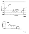
- Fig. 3 shows the course of the stepwise discharge of a detached from the network of the power supply battery B11, B12. Clearly visible are the discharge voltage and the rise of the battery voltage to the quiescent voltage level after switching off the test resistor RT. Characteristic for the discharge behavior is the non-linearity of the discharge curve, whereby the quiescent voltage characteristic carries a nearly linear character with a good approximation. This quiescent voltage characteristic is created by the points of equal rest time after switching off the discharge ( Fig. 4 ).
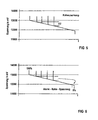
- the battery B11 or B12 In order to determine the required residual capacity for the supply of the load RL in the reserve time, the battery B11 or B12 is disconnected from the generator PV and measured after the settling time, the rest voltage ( Fig. 5 ). Thereafter, a switchover of the battery branches takes place in such a way that the battery B11 or B12, which is separate from the generator PV and is in the idle state, supplies the load RL. After specified, preferably the same time periods, this battery B11 or B12 is disconnected from the load RL, the rest time to reach the quiescent voltage is awaited and the difference of the quiescent voltage is determined from the previous measuring point.
- the alarm rest voltage can be calculated, which indicates the critical voltage level of the available residual energy, such as Fig. 6 shows.
- alarm - Quiet - tension U ⁇ 0 % + dU x reserve time consumer load - test - Time
- This critical discharge voltage of the battery B11, B12 must be corrected for real operating conditions, at least with a temperature compensation.
- the temperature factor is stored in a table in the measuring system.
- the safety factor can be integrated into the reserve time or specified separately.
- This calculation method shows that the alarm silence voltage is always recalculated.
- a reliable residual availability of the energy store can be determined and an autonomous power supply can be operated selectively in accordance with the respective load behavior until the end of the life cycle of the battery.
Landscapes
- Engineering & Computer Science (AREA)
- Power Engineering (AREA)
- General Physics & Mathematics (AREA)
- Chemical Kinetics & Catalysis (AREA)
- Electrochemistry (AREA)
- General Chemical & Material Sciences (AREA)
- Physics & Mathematics (AREA)
- Manufacturing & Machinery (AREA)
- Chemical & Material Sciences (AREA)
- Secondary Cells (AREA)
- Charge And Discharge Circuits For Batteries Or The Like (AREA)
- Hybrid Cells (AREA)
- Tests Of Electric Status Of Batteries (AREA)
- Investigating, Analyzing Materials By Fluorescence Or Luminescence (AREA)
- Photovoltaic Devices (AREA)
- Testing Of Individual Semiconductor Devices (AREA)
Claims (13)
- Procédé d'évaluation de l'état de batteries dans des installations photovoltaïques d'alimentation en courant assistées par batterie, comprenant au moins deux branches parallèles de batterie qui, suivant l'état de charge, alimentent en alternance une charge en énergie ou sont rechargées par un générateur, dans lequel- d'une batterie chargée entrée en service pour la première fois sur l'installation d'alimentation en courant, on enregistre, après déconnexion de l'installation de l'alimentation en courant, au moyen d'une unité de commande automatiquement, dans un cycle de décharge pas à pas sur une résistance de décharge, une courbe caractéristique de décharge de la tension de repos,- on répète ce cycle de décharge pas à pas à des instants fixés pour enregistrer une courbe caractéristique de décharge instantanée de la tension de repos.- on mémorise au moins la courbe caractéristique de décharge instantanée enregistrée en dernier de la tension de repos et- à partir d'un temps de réserve fixé à l'avance et de la tension finale de décharge déterminée lors de la première mesure, on détermine, à partir de la courbe caractéristique de décharge instantanée de la tension de repos, une tension de repos d'alerte, qui représente une mesure de l'énergie résiduelle de la batterie restant encore et on produit, lorsqu'elle est atteinte lors du fonctionnement sur la charge, une alerte de l'opérateur de l'installation de l'alimentation en courant,- caractérisé en ce que l'on détermine, à partir de la diminution du temps de décharge entre des décharges successives de la batterie, l'instant d'enregistrement de la courbe caractéristique de décharge instantanée suivante ou la disponibilité résiduelle de la batterie.
- Procédé suivant la revendication 1, caractérisé en ce que lors de la mesure de la courbe caractéristique de décharge instantanée de la tension de repos, on ne règle que des points individuels marquants de la courbe caractéristique de décharge.
- Procédé suivant l'une des revendications précédentes, caractérisé en ce que l'on détermine outre le temps de réserve, par le même mode que pour le temps de réserve un temps d'avertissement supplémentaire.
- Procédé suivant l'une des revendications précédentes, caractérisé en ce que, après dépassement d'un courant de décharge fixé en fonctionnement normal de la batterie, on enregistre une courbe de décharge instantanée de la tension de repos et on met la batterie hors service si l'on s'écarte au-delà de valeurs fixées de la courbe caractéristique de décharge mémorisée et enregistrée en dernier de la tension de repos.
- Procédé suivant l'une des revendications précédentes, caractérisé en ce que l'on détermine la valeur moyenne du courant de décharge sur la charge et on en détermine et à partir du temps de réserve fixé pour la disponibilité résiduelle de l'alimentation en courant une capacité résiduelle de la batterie, à partir de laquelle on corrige la tension de repos d'alerte au moyen de la courbe de tension de décharge jusqu'à ce que l'on atteigne la tension finale de charge.
- Procédé suivant l'une des revendications 1 à 4, caractérisé en ce qu'en utilisant la charge, on mesure, dans un laps de temps pouvant être déterminé à l'avance, la courbe de la tension de repos et à partir d'elle et du temps de réserve fixé pour la disponibilité résiduelle de l'alimentation en courant ainsi que de la tension finale de décharge, on corrige la tension de repos d'alerte.
- Procédé suivant l'une des revendications précédentes, caractérisé en ce que, pour la tension de repos d'alerte instantanée déterminée, on additionne une valeur qui dépend de la température instantanée.
- Procédé suivant l'une des revendications précédentes, caractérisé en ce qu'en fonctionnement autonome on branche les batteries sur la charge dans une trame de temps choisie et on recharge la batterie branchée respectivement en dernier sur la charge.
- Procédé suivant l'une des revendications 1 à 7, caractérisé en ce qu'en fonctionnement autonome, on décharge la batterie se trouvant sur la charge jusqu'à sa tension de repos d'alerte et on recharge la batterie la plus déchargée.
- Procédé suivant l'une des revendications 1 à 7, caractérisé en ce qu'en fonctionnement autonome, on charge des batteries cycliquement en fonctionnement de secours.
- Procédé suivant les revendications 8 à 10,
caractérisé en ce qu'on inverse cycliquement entre les procédés de charge et les procédés de décharge. - Procédé suivant l'une des revendications précédentes, caractérisé en ce qu'on effectue l'enregistrement de courbes caractéristiques de décharge instantanées de la tension de repos lors de la recharge au moyen des installations photovoltaïques d'alimentation en courant, seulement dans un créneau temporel fixé lorsque le rayonnement solaire est suffisamment intense.
- Procédé suivant la revendication 12, caractérisé en ce que l'on détermine automatiquement la base de temps pour le créneau temporel ainsi que d'autres courbes de fonctionnement et de test sous la forme d'une base de temps relative, indépendante du temps réel, en mesurant les durées quotidiennes de clarté/obscurité ainsi que leur modification par l'installation d'alimentation en courant.
Applications Claiming Priority (2)
| Application Number | Priority Date | Filing Date | Title |
|---|---|---|---|
| DE10201136A DE10201136C1 (de) | 2002-01-08 | 2002-01-08 | Verfahren zur Bewertung des Zustandes von Batterien in batteriegestützten Stromversorgungsanlagen |
| DE10201136 | 2002-01-08 |
Publications (3)
| Publication Number | Publication Date |
|---|---|
| EP1326084A2 EP1326084A2 (fr) | 2003-07-09 |
| EP1326084A3 EP1326084A3 (fr) | 2003-12-03 |
| EP1326084B1 true EP1326084B1 (fr) | 2009-04-22 |
Family
ID=7712095
Family Applications (1)
| Application Number | Title | Priority Date | Filing Date |
|---|---|---|---|
| EP02090423A Expired - Lifetime EP1326084B1 (fr) | 2002-01-08 | 2002-12-20 | Méthode pour la détection de la condition des batteries |
Country Status (6)
| Country | Link |
|---|---|
| EP (1) | EP1326084B1 (fr) |
| AT (1) | ATE429648T1 (fr) |
| DE (2) | DE10201136C1 (fr) |
| DK (1) | DK1326084T3 (fr) |
| ES (1) | ES2324648T3 (fr) |
| PT (1) | PT1326084E (fr) |
Families Citing this family (9)
| Publication number | Priority date | Publication date | Assignee | Title |
|---|---|---|---|---|
| DE102006044297A1 (de) * | 2006-09-20 | 2008-04-03 | Siemens Ag | Verfahren zur Bestimmung eines Betriebszustandes eines Energiespeichers |
| DE102009003843A1 (de) | 2009-04-28 | 2010-12-09 | Ssb Wind Systems Gmbh & Co. Kg | Verfahren zum Betreiben eines Rotorblattverstellantriebs |
| EP3203574A1 (fr) * | 2016-02-08 | 2017-08-09 | Siemens Aktiengesellschaft | Commande de duree de vie pour accumulateur d'energie |
| US11332015B2 (en) | 2017-12-15 | 2022-05-17 | Katlego Systems, Llc | Power supply charging system |
| CN112793461B (zh) * | 2019-11-13 | 2022-04-29 | 上海度普新能源科技有限公司 | 电池管理系统、电动汽车和锂电池的初始状态确定方法 |
| DE102020201836A1 (de) | 2020-02-14 | 2021-08-19 | Robert Bosch Gesellschaft mit beschränkter Haftung | Verfahren zur Bestimmung des Alterungszustandes mindestens einer elektrischen Energiespeichereinheit |
| DE102020202561A1 (de) * | 2020-02-28 | 2021-09-02 | Robert Bosch Gesellschaft mit beschränkter Haftung | Verfahren zum Bestimmen eines Alterungszustands mindestens eines elektrochemischen Energiespeichers |
| CN115792522B (zh) * | 2022-12-08 | 2023-07-28 | 青岛艾测科技有限公司 | 一种容性负载绝缘检测方法、装置和设备 |
| CN116381529B (zh) * | 2023-06-05 | 2023-10-31 | 宁德时代新能源科技股份有限公司 | 电池检测装置、检测方法及电池检测设备 |
Family Cites Families (8)
| Publication number | Priority date | Publication date | Assignee | Title |
|---|---|---|---|---|
| DE3150758C2 (de) * | 1981-12-22 | 1985-03-21 | Deutsche Forschungs- und Versuchsanstalt für Luft- und Raumfahrt e.V., 5300 Bonn | Vorrichtung zur Umwandlung und Speicherung von Solarstrahlungsenergie |
| US4731601A (en) | 1986-12-08 | 1988-03-15 | General Motors Corporation | Cranking system performance indicator |
| DE3821808C2 (de) * | 1988-06-28 | 1994-06-16 | Helmut Haendel & Partner Mesda | Verfahren und Vorrichtung zum automatischen Testen von Akkumulatoren einer unterbrechungsfreien Stromversorgungsanlage |
| GB8817364D0 (en) * | 1988-07-21 | 1988-08-24 | Opalport Electronics Ltd | Battery monitoring system |
| DE3910868A1 (de) * | 1989-04-04 | 1990-12-13 | Jungheinrich Kg | Verfahren zur ermittlung des jeweiligen ladezustandes einer bleibatterie und einrichtung zur durchfuehrung des verfahrens |
| DE4238316A1 (en) * | 1991-11-19 | 1993-05-27 | Meissner Manfred Dipl Ing | Driving system for interruption free current supply - using lower battery discharge voltage equal to lower terminal voltage and lower drop between battery and load input |
| JP3121732B2 (ja) * | 1994-11-04 | 2001-01-09 | 三菱電機株式会社 | 二次電池のパラメータ測定方法ならびにそれを用いた二次電池の充放電制御方法および寿命予測方法、ならびに、二次電池の充放電制御装置およびそれを用いた電力貯蔵装置 |
| DE19605481C1 (de) * | 1996-02-14 | 1997-06-12 | Siemens Ag | Batteriemeßmodul für eine USV-Batterie |
-
2002
- 2002-01-08 DE DE10201136A patent/DE10201136C1/de not_active Expired - Fee Related
- 2002-12-20 PT PT02090423T patent/PT1326084E/pt unknown
- 2002-12-20 DE DE50213472T patent/DE50213472D1/de not_active Expired - Fee Related
- 2002-12-20 DK DK02090423T patent/DK1326084T3/da active
- 2002-12-20 EP EP02090423A patent/EP1326084B1/fr not_active Expired - Lifetime
- 2002-12-20 ES ES02090423T patent/ES2324648T3/es not_active Expired - Lifetime
- 2002-12-20 AT AT02090423T patent/ATE429648T1/de not_active IP Right Cessation
Also Published As
| Publication number | Publication date |
|---|---|
| EP1326084A2 (fr) | 2003-07-09 |
| DK1326084T3 (da) | 2009-08-03 |
| EP1326084A3 (fr) | 2003-12-03 |
| ES2324648T3 (es) | 2009-08-12 |
| ATE429648T1 (de) | 2009-05-15 |
| DE10201136C1 (de) | 2003-06-05 |
| PT1326084E (pt) | 2009-05-06 |
| DE50213472D1 (de) | 2009-06-04 |
Similar Documents
| Publication | Publication Date | Title |
|---|---|---|
| DE69532539T2 (de) | Parametermessverfahren,Verfahren und Vorrichtung zur Steuerung des Ladens und Entladens und Verfahren zur Bestimmung des Lebensendes für Sekundärbatterien und damit ausgerüstetes Energiespeichergerät | |
| DE69216869T2 (de) | Batterieladegerät | |
| DE69732084T2 (de) | Pulsladeverfahren und ladegerät | |
| DE10103431C2 (de) | Stromversorgungs-Einrichtung | |
| DE112018006386T5 (de) | Vorrichtung zur Schätzung der wirtschaftlichen Effizienz einer wiederaufladbaren Batterie sowie Verfahren zur Schätzung der wirtschaftlichen Effizienz | |
| EP2442427B2 (fr) | Dispositif de contrôle d'accumulateur ainsi que procédé et système d'alimentation électrique auxiliaire | |
| US7400149B2 (en) | Method for assessment of the state of batteries in battery-supported power supply systems | |
| DE102017009850B4 (de) | Verfahren zum Auf- und Entladen eines Energiespeichers | |
| DE19818443C2 (de) | Vorrichtung zur Vermeidung einer Schädigung einer Lithium-Sekundärbatterie | |
| DE102013206189B4 (de) | Bestimmen eines Ladezustands eines Akkumulators | |
| WO2014206983A1 (fr) | Procédé et dispositif de stockage d'énergie électrique dans des accumulateurs d'énergie électrochimiques | |
| DE112017003472T5 (de) | Batteriesteuervorrichtung, batteriesystem und fahrzeug | |
| DE102011105417A1 (de) | Batteriespeicherwerk | |
| EP2608348A2 (fr) | Circuit protecteur de décompensation pour une batterie | |
| DE102020122992A1 (de) | Akkupack, ladesystem und verfahren zum steuern eines ladens eines akkupacks | |
| EP3618219B1 (fr) | Procédé de restauration d'un module de batterie sur-déchargé et système d'alimentation ininterruptible correspondant | |
| DE10201136C1 (de) | Verfahren zur Bewertung des Zustandes von Batterien in batteriegestützten Stromversorgungsanlagen | |
| DE102019214343A1 (de) | Verfahren zum Ausgleichen von Ladezuständen eines elektrischen Energiespeichers | |
| DE102014108601B4 (de) | Verfahren zum Anschließen mehrerer Batterieeinheiten an einen zweipoligen Eingang eines bidirektionalen Batteriewandlers sowie bidirektionaler Batteriewandler und Photovoltaikwechselrichter | |
| EP1941594A2 (fr) | Procede de charge pour augmenter la longevite de batteries et dispositif pour le realiser | |
| DE102013005104A1 (de) | Vorrichtung und Verfahren zum Auf- und Entladen eines Energiespeichers | |
| EP4505572B1 (fr) | Procédé de recharge d'un accumulateur d'énergie rechargeable | |
| EP3408921B1 (fr) | Détermination de la capacité d'un accumulateur d'énergie d'une unité d'alimentation en courant continu sans interruption | |
| DE102019126692B4 (de) | Verfahren zum Laden und Entladen eines wiederaufladbaren Energiespeichers und Energiespeichersystem | |
| DE102014202616A1 (de) | Verfahren zum Ermitteln der Lagerfähigkeit einer Batterie |
Legal Events
| Date | Code | Title | Description |
|---|---|---|---|
| PUAI | Public reference made under article 153(3) epc to a published international application that has entered the european phase |
Free format text: ORIGINAL CODE: 0009012 |
|
| AK | Designated contracting states |
Designated state(s): AT BE BG CH CY CZ DE DK EE ES FI FR GB GR IE IT LI LU MC NL PT SE SI SK TR |
|
| AX | Request for extension of the european patent |
Extension state: AL LT LV MK RO |
|
| PUAL | Search report despatched |
Free format text: ORIGINAL CODE: 0009013 |
|
| AK | Designated contracting states |
Kind code of ref document: A3 Designated state(s): AT BE BG CH CY CZ DE DK EE ES FI FR GB GR IE IT LI LU MC NL PT SE SI SK TR |
|
| AX | Request for extension of the european patent |
Extension state: AL LT LV MK RO |
|
| 17P | Request for examination filed |
Effective date: 20040119 |
|
| AKX | Designation fees paid |
Designated state(s): AT BE BG CH CY CZ DE DK EE ES FI FR GB GR IE IT LI LU MC NL PT SE SI SK TR |
|
| 17Q | First examination report despatched |
Effective date: 20080107 |
|
| GRAP | Despatch of communication of intention to grant a patent |
Free format text: ORIGINAL CODE: EPIDOSNIGR1 |
|
| GRAS | Grant fee paid |
Free format text: ORIGINAL CODE: EPIDOSNIGR3 |
|
| GRAA | (expected) grant |
Free format text: ORIGINAL CODE: 0009210 |
|
| AK | Designated contracting states |
Kind code of ref document: B1 Designated state(s): AT BE BG CH CY CZ DE DK EE ES FI FR GB GR IE IT LI LU MC NL PT SE SI SK TR |
|
| REG | Reference to a national code |
Ref country code: GB Ref legal event code: FG4D Free format text: NOT ENGLISH |
|
| REG | Reference to a national code |
Ref country code: CH Ref legal event code: EP |
|
| REG | Reference to a national code |
Ref country code: PT Ref legal event code: SC4A Free format text: AVAILABILITY OF NATIONAL TRANSLATION Effective date: 20090427 |
|
| REG | Reference to a national code |
Ref country code: IE Ref legal event code: FG4D |
|
| REF | Corresponds to: |
Ref document number: 50213472 Country of ref document: DE Date of ref document: 20090604 Kind code of ref document: P |
|
| REG | Reference to a national code |
Ref country code: GR Ref legal event code: EP Ref document number: 20090401440 Country of ref document: GR |
|
| REG | Reference to a national code |
Ref country code: DK Ref legal event code: T3 |
|
| REG | Reference to a national code |
Ref country code: ES Ref legal event code: FG2A Ref document number: 2324648 Country of ref document: ES Kind code of ref document: T3 |
|
| PG25 | Lapsed in a contracting state [announced via postgrant information from national office to epo] |
Ref country code: FI Free format text: LAPSE BECAUSE OF FAILURE TO SUBMIT A TRANSLATION OF THE DESCRIPTION OR TO PAY THE FEE WITHIN THE PRESCRIBED TIME-LIMIT Effective date: 20090422 |
|
| PG25 | Lapsed in a contracting state [announced via postgrant information from national office to epo] |
Ref country code: SI Free format text: LAPSE BECAUSE OF FAILURE TO SUBMIT A TRANSLATION OF THE DESCRIPTION OR TO PAY THE FEE WITHIN THE PRESCRIBED TIME-LIMIT Effective date: 20090422 Ref country code: SE Free format text: LAPSE BECAUSE OF FAILURE TO SUBMIT A TRANSLATION OF THE DESCRIPTION OR TO PAY THE FEE WITHIN THE PRESCRIBED TIME-LIMIT Effective date: 20090722 |
|
| REG | Reference to a national code |
Ref country code: IE Ref legal event code: FD4D |
|
| PG25 | Lapsed in a contracting state [announced via postgrant information from national office to epo] |
Ref country code: EE Free format text: LAPSE BECAUSE OF FAILURE TO SUBMIT A TRANSLATION OF THE DESCRIPTION OR TO PAY THE FEE WITHIN THE PRESCRIBED TIME-LIMIT Effective date: 20090422 Ref country code: IE Free format text: LAPSE BECAUSE OF FAILURE TO SUBMIT A TRANSLATION OF THE DESCRIPTION OR TO PAY THE FEE WITHIN THE PRESCRIBED TIME-LIMIT Effective date: 20090422 Ref country code: CZ Free format text: LAPSE BECAUSE OF FAILURE TO SUBMIT A TRANSLATION OF THE DESCRIPTION OR TO PAY THE FEE WITHIN THE PRESCRIBED TIME-LIMIT Effective date: 20090422 |
|
| PGFP | Annual fee paid to national office [announced via postgrant information from national office to epo] |
Ref country code: AT Payment date: 20091111 Year of fee payment: 8 Ref country code: DK Payment date: 20091208 Year of fee payment: 8 |
|
| PG25 | Lapsed in a contracting state [announced via postgrant information from national office to epo] |
Ref country code: SK Free format text: LAPSE BECAUSE OF FAILURE TO SUBMIT A TRANSLATION OF THE DESCRIPTION OR TO PAY THE FEE WITHIN THE PRESCRIBED TIME-LIMIT Effective date: 20090422 |
|
| PGFP | Annual fee paid to national office [announced via postgrant information from national office to epo] |
Ref country code: NL Payment date: 20091222 Year of fee payment: 8 |
|
| PLBE | No opposition filed within time limit |
Free format text: ORIGINAL CODE: 0009261 |
|
| STAA | Information on the status of an ep patent application or granted ep patent |
Free format text: STATUS: NO OPPOSITION FILED WITHIN TIME LIMIT |
|
| 26N | No opposition filed |
Effective date: 20100125 |
|
| PG25 | Lapsed in a contracting state [announced via postgrant information from national office to epo] |
Ref country code: BG Free format text: LAPSE BECAUSE OF FAILURE TO SUBMIT A TRANSLATION OF THE DESCRIPTION OR TO PAY THE FEE WITHIN THE PRESCRIBED TIME-LIMIT Effective date: 20090722 |
|
| PGFP | Annual fee paid to national office [announced via postgrant information from national office to epo] |
Ref country code: PT Payment date: 20091123 Year of fee payment: 8 |
|
| PGFP | Annual fee paid to national office [announced via postgrant information from national office to epo] |
Ref country code: ES Payment date: 20100126 Year of fee payment: 8 Ref country code: GB Payment date: 20091210 Year of fee payment: 8 |
|
| PGFP | Annual fee paid to national office [announced via postgrant information from national office to epo] |
Ref country code: BE Payment date: 20091216 Year of fee payment: 8 Ref country code: GR Payment date: 20091211 Year of fee payment: 8 |
|
| PG25 | Lapsed in a contracting state [announced via postgrant information from national office to epo] |
Ref country code: MC Free format text: LAPSE BECAUSE OF NON-PAYMENT OF DUE FEES Effective date: 20100701 |
|
| REG | Reference to a national code |
Ref country code: CH Ref legal event code: PL |
|
| REG | Reference to a national code |
Ref country code: FR Ref legal event code: ST Effective date: 20100831 |
|
| PG25 | Lapsed in a contracting state [announced via postgrant information from national office to epo] |
Ref country code: FR Free format text: LAPSE BECAUSE OF NON-PAYMENT OF DUE FEES Effective date: 20091231 Ref country code: CH Free format text: LAPSE BECAUSE OF NON-PAYMENT OF DUE FEES Effective date: 20091231 Ref country code: LI Free format text: LAPSE BECAUSE OF NON-PAYMENT OF DUE FEES Effective date: 20091231 |
|
| PG25 | Lapsed in a contracting state [announced via postgrant information from national office to epo] |
Ref country code: DE Free format text: LAPSE BECAUSE OF NON-PAYMENT OF DUE FEES Effective date: 20100701 |
|
| PG25 | Lapsed in a contracting state [announced via postgrant information from national office to epo] |
Ref country code: IT Free format text: LAPSE BECAUSE OF FAILURE TO SUBMIT A TRANSLATION OF THE DESCRIPTION OR TO PAY THE FEE WITHIN THE PRESCRIBED TIME-LIMIT Effective date: 20090422 |
|
| PG25 | Lapsed in a contracting state [announced via postgrant information from national office to epo] |
Ref country code: LU Free format text: LAPSE BECAUSE OF NON-PAYMENT OF DUE FEES Effective date: 20091220 |
|
| REG | Reference to a national code |
Ref country code: PT Ref legal event code: MM4A Free format text: LAPSE DUE TO NON-PAYMENT OF FEES Effective date: 20110620 |
|
| BERE | Be: lapsed |
Owner name: SIEMENS A.G. Effective date: 20101231 |
|
| REG | Reference to a national code |
Ref country code: NL Ref legal event code: V1 Effective date: 20110701 |
|
| PG25 | Lapsed in a contracting state [announced via postgrant information from national office to epo] |
Ref country code: PT Free format text: LAPSE BECAUSE OF NON-PAYMENT OF DUE FEES Effective date: 20110620 |
|
| REG | Reference to a national code |
Ref country code: DK Ref legal event code: EBP |
|
| GBPC | Gb: european patent ceased through non-payment of renewal fee |
Effective date: 20101220 |
|
| PG25 | Lapsed in a contracting state [announced via postgrant information from national office to epo] |
Ref country code: AT Free format text: LAPSE BECAUSE OF NON-PAYMENT OF DUE FEES Effective date: 20101220 Ref country code: TR Free format text: LAPSE BECAUSE OF FAILURE TO SUBMIT A TRANSLATION OF THE DESCRIPTION OR TO PAY THE FEE WITHIN THE PRESCRIBED TIME-LIMIT Effective date: 20090422 |
|
| PG25 | Lapsed in a contracting state [announced via postgrant information from national office to epo] |
Ref country code: CY Free format text: LAPSE BECAUSE OF FAILURE TO SUBMIT A TRANSLATION OF THE DESCRIPTION OR TO PAY THE FEE WITHIN THE PRESCRIBED TIME-LIMIT Effective date: 20090422 Ref country code: BE Free format text: LAPSE BECAUSE OF NON-PAYMENT OF DUE FEES Effective date: 20101231 |
|
| PG25 | Lapsed in a contracting state [announced via postgrant information from national office to epo] |
Ref country code: GR Free format text: LAPSE BECAUSE OF NON-PAYMENT OF DUE FEES Effective date: 20110704 Ref country code: GB Free format text: LAPSE BECAUSE OF NON-PAYMENT OF DUE FEES Effective date: 20101220 |
|
| PG25 | Lapsed in a contracting state [announced via postgrant information from national office to epo] |
Ref country code: NL Free format text: LAPSE BECAUSE OF NON-PAYMENT OF DUE FEES Effective date: 20110701 |
|
| REG | Reference to a national code |
Ref country code: ES Ref legal event code: FD2A Effective date: 20120411 |
|
| PG25 | Lapsed in a contracting state [announced via postgrant information from national office to epo] |
Ref country code: ES Free format text: LAPSE BECAUSE OF NON-PAYMENT OF DUE FEES Effective date: 20101221 |