EP1326194A2 - Appareil électronique comprenant un tiroir pouvant être chargé avec une carte de sécurité - Google Patents
Appareil électronique comprenant un tiroir pouvant être chargé avec une carte de sécurité Download PDFInfo
- Publication number
- EP1326194A2 EP1326194A2 EP02019660A EP02019660A EP1326194A2 EP 1326194 A2 EP1326194 A2 EP 1326194A2 EP 02019660 A EP02019660 A EP 02019660A EP 02019660 A EP02019660 A EP 02019660A EP 1326194 A2 EP1326194 A2 EP 1326194A2
- Authority
- EP
- European Patent Office
- Prior art keywords
- card
- holder
- cardholder
- locking
- electronic apparatus
- Prior art date
- Legal status (The legal status is an assumption and is not a legal conclusion. Google has not performed a legal analysis and makes no representation as to the accuracy of the status listed.)
- Withdrawn
Links
Images


Classifications
-
- G—PHYSICS
- G06—COMPUTING OR CALCULATING; COUNTING
- G06K—GRAPHICAL DATA READING; PRESENTATION OF DATA; RECORD CARRIERS; HANDLING RECORD CARRIERS
- G06K13/00—Conveying record carriers from one station to another, e.g. from stack to punching mechanism
- G06K13/02—Conveying record carriers from one station to another, e.g. from stack to punching mechanism the record carrier having longitudinal dimension comparable with transverse dimension, e.g. punched card
- G06K13/08—Feeding or discharging cards
- G06K13/085—Feeding or discharging cards using an arrangement for locking the inserted card
-
- G—PHYSICS
- G06—COMPUTING OR CALCULATING; COUNTING
- G06K—GRAPHICAL DATA READING; PRESENTATION OF DATA; RECORD CARRIERS; HANDLING RECORD CARRIERS
- G06K19/00—Record carriers for use with machines and with at least a part designed to carry digital markings
- G06K19/04—Record carriers for use with machines and with at least a part designed to carry digital markings characterised by the shape
-
- G—PHYSICS
- G06—COMPUTING OR CALCULATING; COUNTING
- G06K—GRAPHICAL DATA READING; PRESENTATION OF DATA; RECORD CARRIERS; HANDLING RECORD CARRIERS
- G06K7/00—Methods or arrangements for sensing record carriers, e.g. for reading patterns
Definitions
- the present invention relates to electronic apparatus capable of being loaded with, for example, an SD (secure digital) card, and more specifically, to a structure for preventing the SD card from slipping off.
- SD secure digital
- SD cards that can store masses of image, voice, and other data are widely used in electronic apparatuses such as portable computers and PDAs (personal digital assistants).
- PDAs personal digital assistants
- An electronic apparatus that can be loaded with an SD card is furnished with a card receptacle.
- the card receptacle comprises a card slot into which the SD card can be inserted, a card connector that faces the card slot, and a locking mechanism for holding the SD card in the card receptacle.
- the locking mechanism has a metallic lock lever.
- the lock lever is located between the card slot and the card connector.
- the lock lever has an elastically deformable tongue portion on its distal end, the tongue portion projecting into the card receptacle.
- the tongue portion is elastically fitted into a notch that is formed in a side edge of the card.
- the tongue portion of the lock lever is elastically deformed, yielding to the pull, and is disengaged from the notch. Thereupon, the SD card is released from the locking lever and unlocked, so that it can be taken out of the card receptacle.
- the tongue portion of the lock lever rubs against the side edge of the SD card every time the card is inserted into or drawn out of the card receptacle. At the same time, the tongue portion is fitted into the notch of the card or elastically deformed in a direction such that it slips out of the notch.
- the tongue portion of the lock lever inevitably wears or is lowered in springiness.
- the engagement between the tongue portion of the lock lever and the notch of the SD card may possibly be deficient.
- the SD card easily slips off the card receptacle if any vibration or shock acts on the electronic apparatus, for example.
- the embodiment of the present invention provides an electronic apparatus capable of securely holding a card in a holder and preventing the card from slipping off unexpectedly.
- an electronic apparatus comprises a body and a holder for holding a card.
- the holder is supported on the body, and is movable between a first position in which the holder is held in the body and a second position in which the holder is disengaged from the body.
- the body has an engaging portion. The engaging portion is removably caught by the card in the holder when the holder is moved to the first position.
- the holder In incorporating the card into the body with this configuration, the holder is moved to the second position. After the holder is then loaded with the card, it is moved from the second position to the first position. As this is done, the engaging portion is caught by the card, and the card is locked by means of the holder.
- the holder In taking out the card from the body, the holder is moved from the first position to the second position. As this is done, the card, along with the holder, recedes from the body and is disengaged from the engaging portion of the body. Thus, the card is unlocked.
- the card When the card is incorporated into or removed from the body, according to this configuration, no components rub against it or undergo elastic deformation. Thus, the card can be prevented from being deficiently locked owing to abrasion of the components or lowering of their springiness.
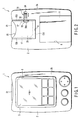
- FIGS. 1 to 4 show a PDA (personal digital assistant) 1 as an electronic apparatus.
- the PDA 1 has a plastic apparatus body 2.
- the body 2 is in the form of a flat box that has a bottom wall 2a, front wall 2b, left- and right-hand sidewalls 2c and 2d, upper end wall 2e, and lower end wall 2f.
- the apparatus body 2 contains a printed wiring board 3 therein.
- the printed wiring board 3 is located parallel to the bottom and front walls 2a and 2b of the body 2.
- a liquid crystal display unit 4 and a tablet 5 are held between the printed wiring board 3 and the front wall 2b.
- the display unit 4 and the tablet 5 overlap each other.
- the tablet 5 has a screen 5a, as shown in FIG. 1.
- the screen 5a is exposed to the outside of the body 2 through an opening 6 in the front wall 2b.
- the apparatus body 2 is provided with a battery storage portion 8 and a holder supporting portion 9.
- the battery storage portion 8 is used to store batteries 10 for use as power sources for the PDA 1.
- the storage portion 8 is formed of a recess that opens in the bottom wall 2a and the lower end wall 2f of the body 2 and is closed by means of a removable battery cover 11.
- the holder supporting portion 9 is situated behind the liquid crystal display unit 4 and in the upper half of the apparatus body 2.
- the supporting portion 9 is formed of a recess in the body 2, which opens in the bottom wall 2a and the upper end wall 2e of the body 2.
- the holder supporting portion 9 has a bottom wall 13a, left- and right-hand sidewalls 13b and 13c, and an end wall 13d.
- the bottom wall 13a is located parallel to the printed wiring board 3.
- the sidewalls 13b and 13c and the end wall 13d rise individually from the edge portions of the bottom wall 13a toward the bottom wall 2a of the body 2.
- a card connector 15 is mounted on the printed wiring board 3.
- the card connector 15 has connecting terminals 16.
- the terminals 16 are arranged in a line in the width direction of the apparatus body 2 and exposed to the holder supporting portion 9 through the bottom wall 13a.
- the holder supporting portion 9 has a pair of engaging projections 17.
- the projections 17 are situated individually in two corner portions that are defined by the bottom wall 13a and the sidewalls 13b and 13c.
- the projections 17 protrude from the walls 13a, 13b and 13c at right angles thereto toward the inner part of the supporting portion 9.
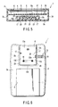
- the holder supporting portion 9 of the apparatus body 2 supports a plastic cardholder 20.
- the cardholder 20 is used to hold an SD (secure digital) card 21 in a removable manner.
- the SD card 21 has contacts 22 and a pair of notches 23.
- the contacts 22 are situated on one end portion of the SD card 21 and arranged in a line in the width direction of the card 21.
- the notches 23 are situated individually in the respective middle portions of the left- and right-hand side edges of the SD card 21.
- the notches 23 are just large enough to receive their corresponding projections 17.
- the cardholder 20 that holds the SD card 21 is in the form of a flat box that can be fitted tight in the holder supporting portion 9.
- the cardholder 20 has a card slot 25 for the insertion and removal of the SD card 21 and an opening 26 through which the contacts 22 of the card 21 can be exposed.
- the card slot 25 is situated at one end of the cardholder 20.
- the opening 26 is situated at the other end of the cardholder 20 opposite from the card slot 25, and faces the connecting terminals 16 of the card connector 15 that are exposed to the holder supporting portion 9.
- the cardholder 20 has a pair of through holes 27, as shown in FIGS. 7 and 8.
- the through holes 27 are situated individually in the left- and right-hand portions of the cardholder 20.
- Each through hole 27 is in the form of a slit that is just large enough for the passage of each corresponding engaging projection 17.
- the through holes 27 can be aligned individually with the notches 23 of the SD card 21 when the card 21 is inserted in the card slot 25.
- the cardholder 20 has a pair of shafts 28 on its other end.
- the shafts 28 are fitted individually in sockets 29 that are bored individually in the sidewalls 13b and 13c of the holder supporting portion 9.
- the cardholder 20 is supported on the apparatus body 2 by means of the shafts 28 so as to be rockable between first and second positions.
- FIGS. 2 and 3 show the cardholder 20 in the first position.
- the cardholder 20 In this first position, the cardholder 20 is held in the holder supporting portion 9. Accordingly, the cardholder 20 overlaps the bottom wall 13a, and its opening 26 faces the connecting terminals 16 of the card connector 15.
- the engaging projections 17 of the holder supporting portion 9 are located in their corresponding through holes 27 and inside the cardholder 20.
- FIG. 4 shows the cardholder 20 in the second position.
- the cardholder 20 In this second position, the cardholder 20 is tilted away from the bottom wall 13a of the holder supporting portion 9 and juts out from the bottom wall 2a of the apparatus body 2. Accordingly, the card slot 25 of the cardholder 20 outwardly projects long from the holder supporting portion 9, and the engaging projections 17 of the supporting portion 9 are disengaged from the through holes 27 of the cardholder 20.
- the apparatus body 2 is provided with a locking mechanism 31 for locking the cardholder 20 in the first position.
- the locking mechanism 31 includes a locking tongue 32 that is supported on the bottom wall 2a of the body 2.
- the tongue 32 has a distal end 32a that adjoins the holder supporting portion 9.
- the locking tongue 32 can slide between a locking position and an unlocking position. When the locking tongue 32 is slid to the locking position, its distal end 32a advances into the holder supporting portion 9 through the sidewall 13c. When the tongue 32 is slid to the unlocking position, the distal end 32a withdraws from the holder supporting portion 9 into the body 2.
- the locking tongue 32 is slid from the locking position to the unlocking position when the cardholder 20 is in the first position, its distal end 32a is disengaged from the engaging hole 33.
- the cardholder 20 is unlocked or released from the locking tongue 32, so that it can be rocked from the first position to the second position.
- the locking tongue 32 has an operating part 34.
- the operating part 34 is exposed to the outside of the bottom wall 2a of the apparatus body 2 so that it is accessible to an operator's fingertip. Thus, the operator can manually slide the locking tongue 32 to the locking or unlocking position.
- the locking tongue 32 is slid from the locking position to the unlocking position, whereupon the cardholder 20 is unlocked or released from the locking tongue 32. Then, the cardholder 20 is rocked from the first position to the second position, whereupon it is lifted from the holder supporting portion 9. In this state, the SD card 21 is put into the card slot 25 of the cardholder 20. The card 21 is inserted into the cardholder 20 with its one end, having the contacts 22, at the head.
- the contacts 22 are exposed to the outside of the cardholder 20 through the opening 26.
- the notches 23 of the card 21 are aligned individually with the through holes 27 of the cardholder 20.
- the cardholder 20 is rocked from the second position to the first position. As this is done, the contacts 22 of the SD card 21 run against the connecting terminals 16 of the card connector 15 so that it is connected electrically to the printed wiring board 3. Subsequently, the cardholder 20 approaches the bottom wall 13a of the holder supporting portion 9, and the engaging projections 17 that protrude from the bottom wall 13a get into the notches 23 of the SD card 21 through the through holes 27, individually. Thereupon, the respective positions of the SD card 21 and the cardholder 20 are fixedly settled, and the card 21 is locked lest it slip out of the cardholder 20.
- the locking tongue 32 is slid from the unlocking position to the locking position. As this is done, the distal end 32a of the locking tongue 32 is caught by the engaging hole 33 of the cardholder 20, whereupon the cardholder 20 is locked in the first position.
- the locking tongue 32 is slid from the locking position to the unlocking position to unlock the cardholder 20. Then, the cardholder 20 is rocked from the first position to the second position. As this is done, the cardholder 20 recedes from the bottom wall 13a of the holder supporting portion 9, and the engaging projections 17 of the supporting portion 9 get out of the notches 23 of the SD card 21 and the through holes 27 of the cardholder 20, individually. Thus, the SD card 21 is unlocked and disengaged from the cardholder 20.
- the contacts 22 of the SD card 21 leave the connecting terminals 16 of the card connector 15, whereupon the card 21 is released from the electrical connection with the printed wiring board 3.
- the card slot 25 outwardly projects long from the apparatus body 2, whereupon the SD card 21 is allowed to be drawn out of the card slot 25.
- the engaging projections 17 of the apparatus body 2 get individually into the notches 23 of the card 21, thereby locking the card 21 in the cardholder 20, or slip out of the notches 23, thereby unlocking the card 21.
- the SD card 21 When the SD card 21 is locked or unlocked, therefore, no components rub against it or undergo elastic deformation. Thus, the card 21 can be prevented from being deficiently locked owing to abrasion of the components or lowering of their springiness. In consequence, the card 21 never unexpectedly slips off the PDA 1 if the PDA 1 is subjected to any vibration or shock. Thus, the SD card 21 can be prevented from being rendered missing or damaged.
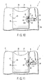
- FIGS. 10 and 11 show a second embodiment of the invention.
- the engaging projections 17 and the locking mechanism 31 are combined together to prevent the SD card 21 from slipping off.
- the second embodiment shares other basic configurations of the PDA 1 with the first embodiment. Therefore, like reference numerals are used to designate like components of the first and second embodiments, and a description of those components will not be repeated.
- the locking tongue 32 of the locking mechanism 31 has an extended portion 41 on its distal end 32a.
- the extended portion 41 is adapted to penetrate the engaging hole 33 of the cardholder 20 in the first position when the locking tongue 32 is slid to the locking position.
- the extended portion 41 is located side by side with the right-hand engaging projection 17 as it advances into the cardholder 20.
- the right-hand notch 23 of the SD card 21 has a receiving portion 42 that is spread so that the extended portion 41 of the locking tongue 32 can get into it.
- the receiving portion 42 faces the engaging hole 33 of the cardholder 20 when the SD card 21 is inserted into the cardholder 20 through the card slot 25.
- the locking tongue 32 serves both as means for preventing the cardholder 20 from opening and as means for preventing the card 21 from slipping off. In consequence, the SD card 21 can be prevented more securely from slipping off.
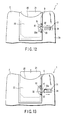
- FIGS. 12 and 13 show a third embodiment of the invention.
- the third embodiment differs from the second embodiment in that the SD card 21 is prevented from slipping off by means of the locking mechanism 31.
- the third embodiment shares other basic configurations of the PDA 1 with the second embodiment.
- the SD card 21 has a notch 51 in its right-hand edge.
- the notch 51 is adapted to face the engaging hole 33 of the cardholder 20 when the card 21 is fully inserted into the cardholder 20.
- the locking tongue 32 If the locking tongue 32 is slid to the locking position with the cardholder 20, having the SD card 21 therein, situated in the first position, therefore, the extended portion 41 of the locking tongue 32 gets into the notch 51 of the card 21 through the engaging hole 33 of the cardholder 20. Accordingly, the locking tongue 32 locks the cardholder 20 in the first position, and at the same time, the SD card 21 is locked lest it slip out of the cardholder 20.
- the holder supporting portion 9 need not be provided with the engaging projections that are caught by the SD card 21, and the through holes that receive the engaging projections need not be formed in the cardholder 20.
- the apparatus body 2 and the cardholder 20 can be simplified in construction, and costs can be lowered.
- the card used in the present invention is not limited to the SD card.
- it may be a memory card, such as a solid-state floppy disc card (SSFDC), or some other IC card.
- SSFDC solid-state floppy disc card
- the electronic apparatus is not limited to the PDA, and may be any other apparatus such as a portable computer or portable telephone.
Landscapes
- Engineering & Computer Science (AREA)
- Physics & Mathematics (AREA)
- General Physics & Mathematics (AREA)
- Theoretical Computer Science (AREA)
- Artificial Intelligence (AREA)
- Computer Vision & Pattern Recognition (AREA)
- Coupling Device And Connection With Printed Circuit (AREA)
- Casings For Electric Apparatus (AREA)
- Credit Cards Or The Like (AREA)
- Details Of Connecting Devices For Male And Female Coupling (AREA)
- Fittings On The Vehicle Exterior For Carrying Loads, And Devices For Holding Or Mounting Articles (AREA)
- Telephone Set Structure (AREA)
Applications Claiming Priority (2)
| Application Number | Priority Date | Filing Date | Title |
|---|---|---|---|
| JP2001392671 | 2001-12-25 | ||
| JP2001392671A JP2003196605A (ja) | 2001-12-25 | 2001-12-25 | 情報処理装置 |
Publications (2)
| Publication Number | Publication Date |
|---|---|
| EP1326194A2 true EP1326194A2 (fr) | 2003-07-09 |
| EP1326194A3 EP1326194A3 (fr) | 2006-09-20 |
Family
ID=19188668
Family Applications (1)
| Application Number | Title | Priority Date | Filing Date |
|---|---|---|---|
| EP02019660A Withdrawn EP1326194A3 (fr) | 2001-12-25 | 2002-09-03 | Appareil électronique comprenant un tiroir pouvant être chargé avec une carte de sécurité |
Country Status (3)
| Country | Link |
|---|---|
| US (1) | US6757172B2 (fr) |
| EP (1) | EP1326194A3 (fr) |
| JP (1) | JP2003196605A (fr) |
Cited By (3)
| Publication number | Priority date | Publication date | Assignee | Title |
|---|---|---|---|---|
| GB2402815A (en) * | 2003-06-11 | 2004-12-15 | Hewlett Packard Development Co | Electronic system with pivoted component, in particular a circuit board |
| WO2013147987A1 (fr) * | 2012-03-29 | 2013-10-03 | Sandisk Technologies Inc. | Dispositif hôte à fente pour carte mémoire et renfoncement pour l'ongle associé |
| WO2014083185A1 (fr) * | 2012-11-30 | 2014-06-05 | Compagnie Industrielle Et Financiere D'ingenierie "Ingenico" | Trappe pour terminal |
Families Citing this family (14)
| Publication number | Priority date | Publication date | Assignee | Title |
|---|---|---|---|---|
| JP3802432B2 (ja) * | 2002-02-14 | 2006-07-26 | ヒロセ電機株式会社 | カード用コネクタ |
| US20050149954A1 (en) * | 2004-01-03 | 2005-07-07 | Chao-Liang Wang | Optical disk drive and casing thereof |
| US7487265B2 (en) * | 2004-04-16 | 2009-02-03 | Sandisk Corporation | Memory card with two standard sets of contacts and a hinged contact covering mechanism |
| US7352592B2 (en) * | 2004-05-21 | 2008-04-01 | Cardiac Pacemakers, Inc. | Method and apparatus for carrying circuit assemblies |
| US7710736B2 (en) * | 2005-08-02 | 2010-05-04 | Sandisk Corporation | Memory card with latching mechanism for hinged cover |
| JP4692767B2 (ja) * | 2006-11-21 | 2011-06-01 | 日本電気株式会社 | カードホルダ基板取付構造 |
| CN101685932B (zh) * | 2008-09-26 | 2012-07-25 | 深圳富泰宏精密工业有限公司 | 芯片卡固持结构 |
| TWM370233U (en) * | 2009-05-12 | 2009-12-01 | Hon Hai Prec Ind Co Ltd | Electrical connector assembly |
| JP5549821B2 (ja) * | 2012-04-17 | 2014-07-16 | 第一精工株式会社 | 電気コネクタ |
| DE202014100895U1 (de) * | 2014-02-27 | 2015-05-29 | Wago Verwaltungsgesellschaft Mbh | Elektrisches Gerät |
| DE102017130005B3 (de) | 2017-12-14 | 2019-06-06 | Harting Electric Gmbh & Co. Kg | Steckverbinder |
| WO2019034203A1 (fr) | 2017-08-18 | 2019-02-21 | Harting Electric Gmbh & Co. Kg | Mécanisme de verrouillage pour boîtier de connecteur |
| DE102017118918A1 (de) * | 2017-08-18 | 2019-02-21 | Harting Electric Gmbh & Co. Kg | Druckknopfverriegelung für ein Steckverbindergehäuse |
| US10320100B2 (en) * | 2017-10-06 | 2019-06-11 | Te Connectivity Corporation | Card edge connector assembly |
Family Cites Families (20)
| Publication number | Priority date | Publication date | Assignee | Title |
|---|---|---|---|---|
| JPS5334893A (en) | 1976-09-11 | 1978-03-31 | Tokyo Yuuki Kagaku Kougiyou Kk | Porous crossslinked copolymers and process for producing porous crossslinked ion exchange resin |
| JPS6390092A (ja) * | 1986-10-01 | 1988-04-20 | Tokyo Electric Co Ltd | Icカ−ドの着脱防止機構 |
| JPH0820919B2 (ja) * | 1989-05-16 | 1996-03-04 | 株式会社東芝 | ハンディターミナル |
| GB2250846B (en) | 1990-12-13 | 1994-08-24 | Technophone Ltd | Card reader |
| US5889649A (en) * | 1994-03-01 | 1999-03-30 | Canon Kabushiki Kaisha | Information processing apparatus and a card-shaped adapter for smaller and larger storage medium |
| JP3068754B2 (ja) * | 1994-09-16 | 2000-07-24 | 松下電器産業株式会社 | プラグインsimの接続装置 |
| JP3078227B2 (ja) | 1996-05-10 | 2000-08-21 | 矢崎総業株式会社 | 電気接続箱 |
| EP0849695A3 (fr) * | 1996-12-20 | 2000-09-06 | Tyco Electronics Logistics AG | Partie d'un porteur de carte |
| GB2327792B (en) * | 1997-07-25 | 2001-09-12 | Nokia Mobile Phones Ltd | A data card housing |
| CN1088861C (zh) * | 1997-10-15 | 2002-08-07 | 姚立和 | 插卡式存储器的转接器 |
| DE19846366C2 (de) * | 1998-04-07 | 2000-07-27 | Itt Mfg Enterprises Inc | Steckkarte für elektronische Geräte |
| US5933328A (en) * | 1998-07-28 | 1999-08-03 | Sandisk Corporation | Compact mechanism for removable insertion of multiple integrated circuit cards into portable and other electronic devices |
| US6062887A (en) * | 1998-08-31 | 2000-05-16 | Motorola, Inc. | Electronic device with dual card reader employing a drawer |
| US6293464B1 (en) * | 1999-01-05 | 2001-09-25 | Jared Joseph Smalley, Jr. | Card reader |
| FI107973B (fi) * | 1999-03-11 | 2001-10-31 | Nokia Mobile Phones Ltd | Menetelmä ja välineet lisäkorttien käyttämiseksi matkaviestimessä |
| DE19913923A1 (de) * | 1999-03-26 | 2000-09-28 | Amphenol Tuchel Elect | Kontaktiereinrichtung für eine SIM-Karte |
| JP4316722B2 (ja) * | 1999-04-13 | 2009-08-19 | 日本圧着端子製造株式会社 | アンテナ付きicカード |
| GB2352912A (en) | 1999-07-30 | 2001-02-07 | Sony Uk Ltd | Method of processing signals and apparatus for signal processing |
| DE20014076U1 (de) * | 2000-08-11 | 2000-10-19 | Reiner Kartengeräte GmbH & Co. KG, 78120 Furtwangen | Chipkarte mit Adapter |
| JP2002109484A (ja) * | 2000-09-26 | 2002-04-12 | Toshiba Corp | 携帯型情報機器 |
-
2001
- 2001-12-25 JP JP2001392671A patent/JP2003196605A/ja active Pending
-
2002
- 2002-09-03 EP EP02019660A patent/EP1326194A3/fr not_active Withdrawn
- 2002-09-05 US US10/234,167 patent/US6757172B2/en not_active Expired - Fee Related
Cited By (7)
| Publication number | Priority date | Publication date | Assignee | Title |
|---|---|---|---|---|
| GB2402815A (en) * | 2003-06-11 | 2004-12-15 | Hewlett Packard Development Co | Electronic system with pivoted component, in particular a circuit board |
| GB2402815B (en) * | 2003-06-11 | 2007-06-27 | Hewlett Packard Development Co | Parallel board connection system and method |
| WO2013147987A1 (fr) * | 2012-03-29 | 2013-10-03 | Sandisk Technologies Inc. | Dispositif hôte à fente pour carte mémoire et renfoncement pour l'ongle associé |
| US8747162B2 (en) | 2012-03-29 | 2014-06-10 | Sandisk Technologies Inc. | Host device with memory card slot having a card gripping-extracting recess |
| WO2014083185A1 (fr) * | 2012-11-30 | 2014-06-05 | Compagnie Industrielle Et Financiere D'ingenierie "Ingenico" | Trappe pour terminal |
| FR2999002A1 (fr) * | 2012-11-30 | 2014-06-06 | Ingenico Sa | Trappe pour terminal |
| US9680242B2 (en) | 2012-11-30 | 2017-06-13 | Ingenico Group | Flap for terminal |
Also Published As
| Publication number | Publication date |
|---|---|
| US6757172B2 (en) | 2004-06-29 |
| EP1326194A3 (fr) | 2006-09-20 |
| JP2003196605A (ja) | 2003-07-11 |
| US20030117783A1 (en) | 2003-06-26 |
Similar Documents
| Publication | Publication Date | Title |
|---|---|---|
| US6757172B2 (en) | Electronic apparatus having holder loaded with SD card | |
| US6385040B2 (en) | Card-shaped storage medium and information processing apparatus having guide portion for the same | |
| KR940001693B1 (ko) | 소형 전자장치의 기능을 확장하기 위한 확장장치 | |
| US6413108B2 (en) | Personal computer peripheral device adapter | |
| CN102480892B (zh) | 芯片卡固持机构及具有该固持机构的便携式电子装置 | |
| CN1326009C (zh) | 装备附加电池的便携式计算机 | |
| US5251105A (en) | Portable electronic apparatus having a battery pack with a mechanism for latching and an independent mechanism for temporarily preventing detachment | |
| US6129572A (en) | Electrical connector with latch to retain IC card | |
| US7172460B2 (en) | Universal serial bus connector with integral shell | |
| US5299089A (en) | Connector device having two storage decks and three contact arrays for one hard disk drive package or two memory cards | |
| US7300314B2 (en) | Socket for trans-flash memory card | |
| JPH01168099A (ja) | 回路カード収容装置 | |
| HUP0100451A2 (hu) | Eltávolítható akkumulátorfedél | |
| EP0317467A2 (fr) | Ensemble enfichable pour cartes de circuit imprimé | |
| US20020027769A1 (en) | Electronic device having two slots different in width | |
| CN113994293B (zh) | 信息处理装置 | |
| US7670165B2 (en) | Restriction mechanism for card | |
| US20090104794A1 (en) | Land grid array connector | |
| EP1191491A2 (fr) | Appareil électronique qui peut recevoir une carte à puce avec une antenne intégrée | |
| US4635225A (en) | Magnetic bubble cassette | |
| JP2003304313A (ja) | カード保持装置およびそれを備えた携帯端末機 | |
| US20050197002A1 (en) | Battery chamber structure | |
| US20070125854A1 (en) | Mounting apparatus for card reader | |
| JP3497604B2 (ja) | 電子機器 | |
| CN111600983A (zh) | 壳体组件及手机 |
Legal Events
| Date | Code | Title | Description |
|---|---|---|---|
| PUAI | Public reference made under article 153(3) epc to a published international application that has entered the european phase |
Free format text: ORIGINAL CODE: 0009012 |
|
| 17P | Request for examination filed |
Effective date: 20020903 |
|
| AK | Designated contracting states |
Designated state(s): AT BE BG CH CY CZ DE DK EE ES FI FR GB GR IE IT LI LU MC NL PT SE SK TR |
|
| AX | Request for extension of the european patent |
Extension state: AL LT LV MK RO SI |
|
| PUAL | Search report despatched |
Free format text: ORIGINAL CODE: 0009013 |
|
| AK | Designated contracting states |
Kind code of ref document: A3 Designated state(s): AT BE BG CH CY CZ DE DK EE ES FI FR GB GR IE IT LI LU MC NL PT SE SK TR |
|
| AX | Request for extension of the european patent |
Extension state: AL LT LV MK RO SI |
|
| 17Q | First examination report despatched |
Effective date: 20061116 |
|
| AKX | Designation fees paid |
Designated state(s): DE FR GB |
|
| STAA | Information on the status of an ep patent application or granted ep patent |
Free format text: STATUS: THE APPLICATION IS DEEMED TO BE WITHDRAWN |
|
| 18D | Application deemed to be withdrawn |
Effective date: 20070328 |