EP1326319A2 - Rotor, Herstellungsverfahren für dengleichen und Drehmaschine - Google Patents
Rotor, Herstellungsverfahren für dengleichen und Drehmaschine Download PDFInfo
- Publication number
- EP1326319A2 EP1326319A2 EP02028189A EP02028189A EP1326319A2 EP 1326319 A2 EP1326319 A2 EP 1326319A2 EP 02028189 A EP02028189 A EP 02028189A EP 02028189 A EP02028189 A EP 02028189A EP 1326319 A2 EP1326319 A2 EP 1326319A2
- Authority
- EP
- European Patent Office
- Prior art keywords
- magnets
- segmented
- magnet
- rotor
- shaft
- Prior art date
- Legal status (The legal status is an assumption and is not a legal conclusion. Google has not performed a legal analysis and makes no representation as to the accuracy of the status listed.)
- Withdrawn
Links
- 238000004519 manufacturing process Methods 0.000 title claims abstract description 15
- 239000003302 ferromagnetic material Substances 0.000 claims abstract description 20
- 239000000696 magnetic material Substances 0.000 claims abstract description 20
- 230000005415 magnetization Effects 0.000 claims description 27
- 239000000463 material Substances 0.000 claims description 23
- 238000000034 method Methods 0.000 claims description 11
- 229910052761 rare earth metal Inorganic materials 0.000 claims description 7
- 229910052751 metal Inorganic materials 0.000 claims description 4
- 239000002184 metal Substances 0.000 claims description 4
- 230000005291 magnetic effect Effects 0.000 description 49
- 230000004907 flux Effects 0.000 description 28
- 238000009826 distribution Methods 0.000 description 16
- 229910000831 Steel Inorganic materials 0.000 description 6
- 239000010959 steel Substances 0.000 description 6
- 230000003247 decreasing effect Effects 0.000 description 5
- 239000000843 powder Substances 0.000 description 5
- 238000011156 evaluation Methods 0.000 description 4
- 238000005259 measurement Methods 0.000 description 4
- 239000011347 resin Substances 0.000 description 4
- 229920005989 resin Polymers 0.000 description 4
- 238000004458 analytical method Methods 0.000 description 3
- 239000006185 dispersion Substances 0.000 description 3
- 229910001172 neodymium magnet Inorganic materials 0.000 description 3
- 239000011368 organic material Substances 0.000 description 3
- 238000002441 X-ray diffraction Methods 0.000 description 2
- 229910045601 alloy Inorganic materials 0.000 description 2
- 239000000956 alloy Substances 0.000 description 2
- 239000007767 bonding agent Substances 0.000 description 2
- 239000000919 ceramic Substances 0.000 description 2
- 230000006698 induction Effects 0.000 description 2
- 238000000465 moulding Methods 0.000 description 2
- 230000002093 peripheral effect Effects 0.000 description 2
- 230000001681 protective effect Effects 0.000 description 2
- 229910000938 samarium–cobalt magnet Inorganic materials 0.000 description 2
- 229910000531 Co alloy Inorganic materials 0.000 description 1
- 229910000990 Ni alloy Inorganic materials 0.000 description 1
- 239000000853 adhesive Substances 0.000 description 1
- 230000001070 adhesive effect Effects 0.000 description 1
- 239000003795 chemical substances by application Substances 0.000 description 1
- 239000002131 composite material Substances 0.000 description 1
- 238000000748 compression moulding Methods 0.000 description 1
- 229910052802 copper Inorganic materials 0.000 description 1
- 238000005260 corrosion Methods 0.000 description 1
- 230000007797 corrosion Effects 0.000 description 1
- 230000000694 effects Effects 0.000 description 1
- 230000005484 gravity Effects 0.000 description 1
- 238000001746 injection moulding Methods 0.000 description 1
- 238000007689 inspection Methods 0.000 description 1
- 229910000765 intermetallic Inorganic materials 0.000 description 1
- 229910052742 iron Inorganic materials 0.000 description 1
- 238000003754 machining Methods 0.000 description 1
- 239000006247 magnetic powder Substances 0.000 description 1
- 150000002739 metals Chemical class 0.000 description 1
- 239000000203 mixture Substances 0.000 description 1
- 150000004767 nitrides Chemical class 0.000 description 1
- 239000004065 semiconductor Substances 0.000 description 1
- 238000005245 sintering Methods 0.000 description 1
- 238000012916 structural analysis Methods 0.000 description 1
- 239000000126 substance Substances 0.000 description 1
- 238000004381 surface treatment Methods 0.000 description 1
- 229920001187 thermosetting polymer Polymers 0.000 description 1
Images


Classifications
-
- H—ELECTRICITY
- H02—GENERATION; CONVERSION OR DISTRIBUTION OF ELECTRIC POWER
- H02K—DYNAMO-ELECTRIC MACHINES
- H02K1/00—Details of the magnetic circuit
- H02K1/06—Details of the magnetic circuit characterised by the shape, form or construction
- H02K1/22—Rotating parts of the magnetic circuit
- H02K1/27—Rotor cores with permanent magnets
- H02K1/2706—Inner rotors
- H02K1/272—Inner rotors the magnetisation axis of the magnets being perpendicular to the rotor axis
- H02K1/274—Inner rotors the magnetisation axis of the magnets being perpendicular to the rotor axis the rotor consisting of two or more circumferentially positioned magnets
- H02K1/2753—Inner rotors the magnetisation axis of the magnets being perpendicular to the rotor axis the rotor consisting of two or more circumferentially positioned magnets the rotor consisting of magnets or groups of magnets arranged with alternating polarity
- H02K1/278—Surface mounted magnets; Inset magnets
-
- H—ELECTRICITY
- H02—GENERATION; CONVERSION OR DISTRIBUTION OF ELECTRIC POWER
- H02K—DYNAMO-ELECTRIC MACHINES
- H02K15/00—Processes or apparatus specially adapted for manufacturing, assembling, maintaining or repairing of dynamo-electric machines
- H02K15/02—Processes or apparatus specially adapted for manufacturing, assembling, maintaining or repairing of dynamo-electric machines of stator or rotor bodies
- H02K15/03—Processes or apparatus specially adapted for manufacturing, assembling, maintaining or repairing of dynamo-electric machines of stator or rotor bodies having permanent magnets
Definitions
- the present invention relates to a novel rotor for a motor using a rotor having magnets arranged in the outer periphery of the rotating shaft, a method of manufacturing the rotor and a rotary machine.
- Japanese Patent Application Laid-Open No.7-336916 discloses an example in which the direction of magnetization of a magnet is continuously varied in the circumferential direction and the divided magnets are arranged in the circumferential direction.
- the bore diameter of the shaft bore can be made large by employing polar anisotropic magnets.
- the gazette also shows that the N-pole segments and the S-pole segments are alternately arranged in the circumferential direction of the outer periphery of a cylindrical yoke so as to attract one another.
- the gap between the arc segment-shaped magnets in the circumferential direction of the rotor needs to be correctly adjusted. If the motor characteristics such as induced voltage, cogging torque and so on can be satisfied by widening the gap between the arc segment-shaped magnets, the magnet volume of the motor can be reduced. If the gap between the arc segment-shaped magnets is set, the motor can be manufactured in taking the magnet shape tolerance into consideration. Since mass-produced magnets have dispersion in anisotropy, dispersion in orientation and errors in magnetization, the motor needs to be designed in taking these dispersions into consideration.
- the surface magnetic flux density in the case of forming the magnetization direction distribution described above is increased about 1.2 to 1.5 times as large as the surface magnetic flux density in the case of radial magnets each of which is magnetized in a radial direction or has magnetic anisotropy.
- the cogging torque in the sinusoidal magnetization distribution becomes smaller than the cogging torque in the case of the radial magnets. Therefore, when the induced voltage is made nearly equal to that in the case of the radial magnets, the magnet volume in the case of the sinusoidal magnetization distribution can be decreased smaller than the magnet volume in the case of the radial magnets.
- the rotor is mainly composed of magnets, a shaft, a magnet fixing agent (a bonding agent or a supporting material) and magnetic steel sheets.
- the magnet is the lowest in productivity, and the productivity of a magnet comprising a rear-earth element is particularly low. Therefore, reduction of the magnet volume results in improvement of the productivity of the rotor or the motor.
- the weight of the rotor can be reduced.
- An object of the present invention is to provide a rotor which has a high induced voltage characteristic and a low cogging torque characteristic and can reduce the magnet volume smaller than the magnet volume of a ring-shaped magnet of one piece, and also to provide a method of manufacturing the rotor and a rotary machine using the rotor.
- the present invention is characterized by a rotor having magnets segmented in a circumferential direction of a periphery of a shaft, wherein magnetizing directions of the segmented magnets continuously vary, and a non-magnetic material or a ferromagnetic material is interposed in a circumferential gap between the segmented magnets.
- the rotor in accordance with the present invention is characterized in that a direction of a line of magnetic force in each of the segmented magnets in a circumferential center of each of the segmented magnets is directed to a radial direction, and directions of lines of magnetic force in each of the segmented magnets in both sides of the center of the magnet continuously vary with respect to the line of magnetic force in the center and are directed toward directions intersecting with the line of magnetic force in the center, as shown in FIG. 1; and by that magnetizing directions of the magnet continuously vary; and that a non-magnetic material or a ferromagnetic material is interposed in a circumferential gap between the segmented magnets.
- the distribution of the magnetic flux densities has a harmonic component in the sinusoidal waveform.
- the magnetizing directions and the magnetized directions described above are equal to the directions of the lines of magnetic force, and the directions of lines of magnetic force in both sides of the center are directed toward directions intersecting with the magnetizing direction or the magnetized direction in the center, and the directions of the lines of magnetic force in both sides nearer to the center are nearly parallel to the magnetizing or magnetized direction in the center, and the degrees of the intersecting angle of the lines of magnetic force closer to the both ends of the segment magnet are larger.
- the present invention is characterized by a rotor having magnets segmented in a circumferential direction of a periphery of a shaft, wherein each of the segmented magnets has a polar anisotropy and is formed of a bond magnet or a sintered magnet containing a rare-earth element, and a non-magnetic material or a ferromagnetic material is interposed in a circumferential gap between the segmented magnets.
- the polar anisotropies in the magnetizing direction, the magnetized direction and the direction of magnetic force are the same as those described above, and all the anisotropies are the radial anisotropies of the radial direction.
- the magnet is formed of an isotropic magnet or an anisotropic magnet containing a rare-earth element.
- the bond magnet is made of a bonded material composed of a magnet substance and an organic resin.
- the present invention is characterized by that the segmented magnets are formed by flowing current in a direction along an axis of the shaft to magnetize the segmented magnets; and that the method comprises the steps of arranging coils so that a longitudinal direction of each of the coils is along an axis of said shaft, and forming the magnets by flowing current through the coils to magnetize the segmented magnets.
- Each of the segmented magnets is made of a metal containing a rare-earth element, and the magnetization may be performed before attaching the segmented magnets or after attaching the segmented magnets to said shaft.
- magnetization of the arc segment-shaped magnets continuously varies in the circumferential direction.
- the distribution of magnetic flux densities on the surface of the rotor also become a nearly sinusoidal waveform. Therefore, it is possible to provide a rotor in which the magnetized directions of the magnet vary in a sinusoidal waveform in the circumferential direction inside the magnet, the magnetic flux densities on the surface of the magnet showing a sinusoidal waveform distribution, the magnet volume of the arc segment-shaped magnets with the sinusoidal waveform distribution of magnetization being limited to a small amount, and the productivity being high, desirable motor characteristics being ensured.
- the rotor comprises the magnets and the shaft, and the rotor is called as a surface magnet rotor when the magnets are arranged on the surface of the rotor.
- the magnets are segmented in the circumferential direction. In a case where the magnet is segmented, for example, into 8 pieces, each of the segmented magnets corresponds to one pole.
- a surface magnet rotor using a ring-shaped magnet of one piece instead of the arc segment-shaped magnets described above is also put in practical use. In order to reduce a magnet volume in the surface magnet rotor using the ring-shaped magnet, it is effective to thinning the thickness of the ring-shaped magnet. However, the surface magnetic flux density is decreased.
- the magnetic flux density is also decreased when the magnet thickness is thinned.
- a magnetic flux density 1.2 to 1.5 times higher than that in the radial magnetization can be obtained by using the magnets magnetized in a nearly sinusoidal waveform. Therefore, in order to obtain the surface magnetic flux density (the maximum value) equal to that in the case of the radial magnetization, the volume of the segmented magnets magnetized in the sinusoidal waveform can be decreased.
- the ratio of (inner diameter) / (outer diameter) of the segmented magnet is preferably smaller than 0.9. When the ratio is larger than 0.9, the surface magnetic flux density is rapidly decreased, and accordingly it is not preferable from the viewpoint of mass production.
- the lower limit of the ratio is preferably larger than 0.5.
- FIG. 8 shows a measured result of a magnetic flux density distribution in the radial direction on the magnet surface for two pole portions, and the waveform is near sinusoidal.
- a light-weight non-magnetic material (an alloy of Al, Mg or the like) is used for the material of the rotor shaft because the magnetic flux toward the inner peripheral side of the magnet becomes small due to the magnetization in the near sinusoidal waveform.
- the magnet volume ratio is preferably larger than 40 %.
- the magnet volume ratio is preferably in the range of 55 % to 95 %.
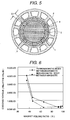
- FIG. 2 is a cross-sectional view showing a rotor in accordance with the present invention.
- the number of poles should be two poles or more.
- FIG. 2 shows a case of 8 poles, and a ratio of (inner diameter) / (outer diameter) is 0.7 to 0.8.
- a magnet is segmented in the circumferential direction, and one segment of the magnet corresponds to one pole.
- a rotor shaft 3 is machined, and the surface of the rotor shaft is cleaned and applied with an adhesive. Then the segmented magnets 1 are fixed onto the rotor.
- magnetization of the magnets there are a method in which the magnets magnetized before bonding are bonded onto the rotor shaft 3 and a method in which non-magnetized segmented magnets are bonded onto the rotor shaft 3 and then magnetized. Either of the above methods may be employed.
- the rotor After assembling the rotor, the rotor is set in the center of a stator 2. In the present embodiment, there exists a gap ⁇ 1 in the circumferential direction between the segmented magnets. The amount of the magnets used therein can be reduced by increasing the gap ⁇ 1.
- a method of the magnetization is that coils are arranged so that a longitudinal direction of the coils is along an axis of the rotor shaft 3, and current is flowed through said coils in directions different from each other with respect to individual magnets adjacent to each other.
- the segmented magnet 1 may be any one of an isotropic bond magnet, an anisotropic bond magnet, an isotropic sintered magnet and as anisotropic sintered magnet.
- an isotropic bond magnet a magnet made of an intermetallic compound of Nd 2 Fe 14 B group, Sm 2 Co 17 group, SmCo 5 group or Sm 2 Fe 17 N 3 group, and magnets made of a composite which is formed by bonding powder of one of these magnet materials with a mixed organic resin are applicable.
- an Sm 2 Co 17 group material or an NdFeB group material of coersive force kA/m (18koe) is used because the magnet material should be a high temperature resistant material.
- the motor can be used within the temperature range of 200 °C to 230 °C.
- Injection molding, compression molding etc are used for manufacturing the arc segment magnet, and machining of the inner circumference and the outer circumference after molding can be eliminated.
- the direction of magnetization of the magnet is determined by the direction of magnetizing magnetic field. Therefore, the magnets can be magnetized each pole using a magnetizing yoke, and then bonded onto the rotor shaft to form the rotor.
- the anisotropic bond magnet the same group materials as the materials for the isotropic bond magnet can be selected, and directions of the anisotropy are adjusted before magnetizing by adding a magnetic field or stress to the magnet at manufacturing the magnets.
- the coil position at molding and the yoke shape are designed so that the distribution of easily magnetized directions may become a sinusoidal waveform with respect to the circumferential direction.
- Evaluation of the direction of the anisotropy and the magnetized direction after being magnetized can be performed through magnetization measurement, magneto-optical measurement or structural measurement.
- the NbFeB group or the Sm 2 Co 17 group material is used as the anisotropic sintered magnet material.
- a rear earth element (Dr, Tb or the like) or Co may be added to the NbFeB group material.
- the magnetic powder When the segmented magnet 1 is manufactured with the anisotropic sintered magnet, the magnetic powder needs to be oriented (in a sinusoidal waveform) before the sintering process. Therefore, it is important that the magnetic field distribution at the magnet position is form in a nearly sinusoidal waveform by designing the coil position and the orientating yoke shape. In order to check the near sinusoidal waveform orientation or magnetization before and after magnetization, the following evaluation methods are used.
- the evaluation methods are (1) a waveform analysis by measuring a distribution of the surface magnetic flux density using a hole element to obtain the angular dependence of the magnetic flux density; (2) an analysis of the angular dependence of the magnetization by evaluating by arranging the segment magnets in a ring-shape to evaluate angular dependences of magnetization (before and after magnetization); (3) an analysis of the angular dependence (positional dependence) of a loop obtained by measuring a magnetized state on the magnet surface of the segmented magnet one by one using the magneto-optical effect; and (4) an structural analysis in the circumferential direction, in the case of the anisotropic magnet. All the methods (1) to (4) can be also used for the ring magnet.
- the gap ⁇ 1 in FIG. 2 is above 0.1 mm, and a non-magnetic material or a ferromagnetic material is inserted to the gap between the magnets.
- the non-magnetic material Al, Cu, Mg or the other non-magnetic metal or alloy, or a resin is used. Further, as the ferromagnetic material, an Fe group material is used. In any cases, the magnets can be integrated with the shaft.
- the segment magnets 1 can be magnetized at a time after fixing the segment magnets 1 onto the rotor shaft 3. That is, post-magnetization can be performed.
- the post-magnetization can be applied to the isotropic magnets as well as to the anisotropic magnets.
- the magnets are magnetized by inserting the rotor into a magnetizing apparatus composed of magnetizing coils and laminate steel plates, and positioning the magnets of the rotor, and then making current flow through the coils.
- Arrangement of the coils are that several numbers of coils are placed in each position of the predetermined arrangement, and the coils are arranged near the boundary between the segment magnets 1 so that a longitudinal direction of the coils is along an axis of the rotor shaft 3, and current is flowed through said coils so that the current may flow in directions different from each other with respect to individual magnets adjacent to each other. Therefore, the coils are individually placed at all the positions between the magnets, and the direction of current flow is along the axis of the rotor shaft, as described above.
- laminar magnetic steel plates or ceramics may be employed for the rotor shaft. It has been checked that the magnetic flux density distribution on the magnet surfaces obtained by the post-magnetization is nearly sinusoidal, and agrees with the magnetic flux density distribution obtained by the case of assembling the magnetized magnets.
- the rotor shaft is made of an organic material, a ceramic or the like.
- the laminar steel plates may be integrated with the rotor shaft in a one-piece structure, or the rotor shaft may be made of a Fe or Ni or Co alloy.
- FIG. 3 is a cross-sectional view showing a rotor shaft in a case of about 75 % magnet volume ratio, and the structure is similar to that of FIG. 2.
- FIG. 4 shows an embodiment in which the segment magnets 1 and the ferromagnetic material member 4 are alternatively arranged in the circumferential direction of the segment magnets 1.
- the saturation magnetic flux density of the ferromagnetic material is above 1.0 T, and the rotor shaft 3 and the ferromagnetic material members 4 may be integrated together when the rotor shaft 3 is made of a magnetic material.
- the segment magnets and the ferromagnetic material members are alternatively arranged.
- the eddy current in the ferromagnetic material member 4 can be reduced by forming the ferromagnetic material member 4 and the rotor shaft 3 of integrated laminar magnetic steel plates. Further, eddy current is easily generated in the segment magnet because the specific resistance of the NdFeB group or the SmCo group sintered magnet is small.
- the bond magnets may be used, or magnets made of a mixture of NbFeB or SmCo group magnet powder and an oxide or nitride powder, or magnet solidified magnet powder after surface treatment of the magnet powder may be used.
- FIG. 6 and FIG. 7 shows the results of measured cogging torque and induced voltage obtained by rotating rotors having the structure described above inside a stator 2, respectively.
- FIG. 6 and FIG. 7 shows a case where a non-magnetic material (an organic material) member is interposed between the magnets and a case where the laminar magnetic steel plates are used.
- the cogging torque in the case where the ferromagnetic material member is interposed between the segment magnets is larger than that in the case where the non-magnetic material member is interposed between the segment magnets.
- the induced voltage is also large. It can be understood that in order to realize low cogging torque and to reduce the magnet volume, the non-magnetic material member should be interposed between the magnets.
- the cogging torque is preferably smaller than 1.00E-03
- the cogging torque in the both cases is slightly improved by interposing the ferromagnetic material member or the non-magnetic material member between the magnets compared to that in the case of 100 % magnet volume ratio.
- the cogging torque down to 60 % magnet volume ratio is nearly equal to that in the case of 100 % magnet volume ratio.
- FIG. 5 shows an embodiment in which projections 6 are provided to the rotor shaft 3 in order to make assembling of the segment magnets 1 easy, and organic material member 5 made of a thermosetting resin is interposed into the gap between the magnets. Further, a ring-shaped magnet supporting member can be set in the outer circumference in the rotor so that the rotor withstands the stress at rotating. The segment magnet 1 is bonded with a bonding agent.
- FIG. 8 shows a measured result of a surface magnetic flux density distribution on segment magnets for two pole portions after magnetizing the segment magnets. A point of inflection is observed at a point near 36 degrees because the non-magnetic gap exists between the magnets. Because of the nearly sinusoidal magnetization, the maximum magnetic flux density is higher than that in the case of the radial magnetization. Therefore, the magnetic flux exceeding the magnetic flux in the case of the radial ring magnet can be kept even when the magnet volume is reduced.
- the segment magnets are arranged in a ring shape to measure degree of orientation in the c-axis direction by X-ray diffraction.
- FIG. 9 shows the measured result of the degree of orientation in the c-axis direction of the segment magnets (two pole portions). That is, an X-ray diffraction pattern is measured by rotating a ring-shaped sample, and the ratios of a (006) diffraction peak intensity to the other peak intensities are obtained.
- FIG. 9 shows the data of the ratios.
- the segment magnets are arranged in a ring shape, and the X-ray beam is incident to the magnet from a direction normal to the cross section of FIG. 2 to FIG. 5.
- the X-ray is collimated and incident to the side face of the segment magnet, and the reflected intensity is measured.
- the diffraction pattern is measured for each rotation angle of the sample.
- a degree of orientation of a specified face can be obtained by dividing a diffraction peak intensity of the specified face index by the sum of the total peak intensities.
- a stage having a transferring accuracy higher than that of the measurement angle width or the X-ray width (in the angular direction) is used.
- the diffraction intensity of the c-axis shows the maximum value in the pole center of the segment magnet, and the degree of orientation is above 90 %.
- the rotor having the segment magnets magnetized in the nearly sinusoidal waveform and having the non-magnetic material or ferromagnetic material member in each gap between the magnets, it is possible to provide a rotor which has high induced voltage and low cogging torque characteristics, and is high in the productivity and light in weight. Further, it is possible to easily perform inspection at mass-production in regard to an evaluating method of the anisotropy and the magnetized direction.
- the rotor in accordance with the present invention is effective in application to a servo motor, and is suitable for a motor for transferring semiconductor devices and for a motor for positioning in a machine tool.
Landscapes
- Engineering & Computer Science (AREA)
- Power Engineering (AREA)
- Manufacturing & Machinery (AREA)
- Permanent Field Magnets Of Synchronous Machinery (AREA)
- Manufacture Of Motors, Generators (AREA)
- Permanent Magnet Type Synchronous Machine (AREA)
Applications Claiming Priority (2)
| Application Number | Priority Date | Filing Date | Title |
|---|---|---|---|
| JP2001391337A JP2003199274A (ja) | 2001-12-25 | 2001-12-25 | 回転子とその製造法及び回転機 |
| JP2001391337 | 2001-12-25 |
Publications (2)
| Publication Number | Publication Date |
|---|---|
| EP1326319A2 true EP1326319A2 (de) | 2003-07-09 |
| EP1326319A3 EP1326319A3 (de) | 2004-01-28 |
Family
ID=19188507
Family Applications (1)
| Application Number | Title | Priority Date | Filing Date |
|---|---|---|---|
| EP02028189A Withdrawn EP1326319A3 (de) | 2001-12-25 | 2002-12-19 | Rotor, Herstellungsverfahren für dengleichen und Drehmaschine |
Country Status (4)
| Country | Link |
|---|---|
| US (2) | US20030117032A1 (de) |
| EP (1) | EP1326319A3 (de) |
| JP (1) | JP2003199274A (de) |
| CN (1) | CN1428915A (de) |
Cited By (4)
| Publication number | Priority date | Publication date | Assignee | Title |
|---|---|---|---|---|
| DE102005030826A1 (de) * | 2005-07-01 | 2007-01-04 | Siemens Ag | Synchronmaschine |
| FR3074375A1 (fr) * | 2017-11-27 | 2019-05-31 | Erneo | Rotor cylindrique a champ radial, et machine electrique et/ou magnetique comprenant un tel rotor |
| EP3379703A4 (de) * | 2015-11-19 | 2019-08-21 | Nitto Denko Corporation | Sinterkörper zur herstellung eines seltenerdmagneten und durch magnetisierung dieses sinterkörpers hergestellter seltenerd-permanentmagnet |
| EP3637060A3 (de) * | 2013-01-30 | 2020-04-29 | Arnold Magnetic Technologies AG | Magneten mit konturiertem feld |
Families Citing this family (32)
| Publication number | Priority date | Publication date | Assignee | Title |
|---|---|---|---|---|
| JP4487173B2 (ja) * | 2003-09-19 | 2010-06-23 | 株式会社安川電機 | マイクロサーボモータ用回転子およびこの回転子を備えたマイクロサーポモータ |
| DE102004017507A1 (de) * | 2004-04-08 | 2005-10-27 | Minebea Co., Ltd. | Rotoranordnung für eine elektrische Maschine |
| DE102004044701B4 (de) * | 2004-09-15 | 2008-01-31 | Siemens Ag | Synchronmaschine |
| JP4796788B2 (ja) * | 2005-05-10 | 2011-10-19 | 株式会社日立製作所 | コアレスモータ |
| JP4692090B2 (ja) * | 2005-06-16 | 2011-06-01 | 株式会社富士通ゼネラル | アキシャルエアギャップ型電動機 |
| JP4068653B2 (ja) * | 2006-05-31 | 2008-03-26 | 山洋電気株式会社 | モータ用回転子 |
| KR20080026874A (ko) * | 2006-09-21 | 2008-03-26 | 엘지전자 주식회사 | 외전형 팬모터 및 외전형 팬모터용 자석의 착자방법 |
| JP5157138B2 (ja) * | 2006-11-24 | 2013-03-06 | 株式会社日立製作所 | 永久磁石式回転電機及び風力発電システム |
| KR101279513B1 (ko) * | 2007-01-04 | 2013-06-28 | 엘지전자 주식회사 | 비엘디시 모터 및 이를 구비한 세탁기 |
| JP5359192B2 (ja) * | 2007-11-12 | 2013-12-04 | パナソニック株式会社 | 異方性永久磁石型モータ |
| KR101392926B1 (ko) * | 2008-02-14 | 2014-05-12 | 엘지전자 주식회사 | 팬-모터 조립체 및 이를 구비한 냉장고 |
| WO2010007673A1 (ja) * | 2008-07-16 | 2010-01-21 | ミネベア株式会社 | 希土類-鉄系環状磁石の製造方法、及びモータ |
| FR2945388B1 (fr) * | 2009-05-11 | 2013-04-12 | Moving Magnet Technologies M M T | Moteur electrique triphase a faible couple de detente |
| WO2012090841A1 (ja) | 2010-12-28 | 2012-07-05 | 日立金属株式会社 | 極異方性配向を有する円弧状磁石、その製造方法、及びそれを製造するための金型 |
| JP2013062889A (ja) * | 2011-09-10 | 2013-04-04 | Nidec Servo Corp | ブラシレスdcモータ |
| JP2013106499A (ja) * | 2011-11-16 | 2013-05-30 | Aisin Seiki Co Ltd | 回転電機および回転電機のロータ |
| JP5929153B2 (ja) * | 2011-12-14 | 2016-06-01 | 日産自動車株式会社 | 界磁極用磁石体の製造装置およびその製造方法 |
| US10734877B2 (en) * | 2014-06-10 | 2020-08-04 | The Regents Of The Unversity Of Michigan | Electromagnetic energy transducer |
| BR102014014089A2 (pt) * | 2014-06-10 | 2016-01-05 | Jorg Zimmermann | sistema de enrolamento de bobinas |
| WO2017002873A1 (ja) * | 2015-06-29 | 2017-01-05 | 株式会社ミツバ | ブラシレスモータ |
| CN105375664A (zh) * | 2015-10-29 | 2016-03-02 | 哈尔滨工业大学 | 较快响应的表贴式外转子永磁同步电机 |
| CN105226904A (zh) * | 2015-10-29 | 2016-01-06 | 哈尔滨工业大学 | 较快响应的表贴式内转子永磁同步电机 |
| GB2549694A (en) * | 2016-04-04 | 2017-11-01 | Vastech Holdings Ltd | Electric motor |
| JP6841130B2 (ja) * | 2017-03-30 | 2021-03-10 | Tdk株式会社 | モータ |
| GB2563615B (en) * | 2017-06-20 | 2020-02-12 | Dyson Technology Ltd | A rotor assembly and method of manufacture thereof |
| JP6702378B2 (ja) * | 2018-09-10 | 2020-06-03 | 株式会社明電舎 | 永久磁石表面貼付形回転機の回転子およびその製造方法 |
| CN110649732B (zh) * | 2019-10-28 | 2024-02-23 | 山东大学 | 混合励磁转子及混合励磁表贴式永磁电机 |
| CN110943557A (zh) * | 2019-11-14 | 2020-03-31 | 湖南大学 | 一种Halbach阵列永磁同步电机 |
| US11735966B2 (en) * | 2020-12-30 | 2023-08-22 | Wolong Electric Group Co., Ltd. | Surface-mounted high-speed permanent magnet synchronous rotor |
| JP2022178605A (ja) * | 2021-05-20 | 2022-12-02 | セイコーエプソン株式会社 | アキシャルギャップモーター、ラジアルギャップモーターおよびロボット |
| JP2022178604A (ja) * | 2021-05-20 | 2022-12-02 | セイコーエプソン株式会社 | アキシャルギャップモーター、ラジアルギャップモーターおよびロボット |
| WO2026038505A1 (ja) * | 2024-08-14 | 2026-02-19 | 日本特殊陶業株式会社 | ロータ部材、ロータ、アキシャルギャップモータ、および、モータ |
Family Cites Families (14)
| Publication number | Priority date | Publication date | Assignee | Title |
|---|---|---|---|---|
| CS213709B1 (en) * | 1979-03-13 | 1982-04-09 | Vaclav Landa | Anizotropous permanent magnets |
| US4438362A (en) * | 1982-08-19 | 1984-03-20 | Rotron, Incorporated | Self-starting, direct current motor with permanent magnets of varied magnetic strength |
| JPH0279738A (ja) * | 1988-09-12 | 1990-03-20 | Mitsubishi Electric Corp | 同期式acサーボモータの回転子 |
| US5280209A (en) * | 1989-11-14 | 1994-01-18 | The United States Of America As Represented By The Secretary Of The Army | Permanent magnet structure for use in electric machinery |
| US5204572A (en) * | 1990-09-13 | 1993-04-20 | Sundstrand Corporation | Radial magnetic coupling |
| JPH04185246A (ja) * | 1990-11-20 | 1992-07-02 | Aisin Aw Co Ltd | 回転界磁型モータ用ロータ |
| US5783890A (en) * | 1995-06-26 | 1998-07-21 | Cleveland Motion Controls, Inc. | Imprinted geometric magnetic anticog permanent magnet motor |
| JP3224193B2 (ja) * | 1996-04-24 | 2001-10-29 | 本田技研工業株式会社 | 着磁装置 |
| BR9601756A (pt) * | 1996-05-29 | 1998-09-29 | Brasil Compressores Sa | Capa para rotor de motor elétrico |
| US6169352B1 (en) * | 1997-07-21 | 2001-01-02 | University Of Chicago | Trapped field internal dipole superconducting motor generator |
| US6111332A (en) * | 1998-02-03 | 2000-08-29 | The Regents Of The University Of California | Combined passive bearing element/generator motor |
| EP0978930A1 (de) * | 1998-08-07 | 2000-02-09 | Hitachi Metals, Ltd. | Permanentmagnetgenerator benutzbar in einer Diskette und Diskette mit diesem Generator |
| JP3779097B2 (ja) * | 1999-07-23 | 2006-05-24 | 日本電産サンキョー株式会社 | 電動機の回転子 |
| JP2001314050A (ja) * | 2000-04-27 | 2001-11-09 | Sony Corp | Acサーボ・モータ |
-
2001
- 2001-12-25 JP JP2001391337A patent/JP2003199274A/ja not_active Withdrawn
-
2002
- 2002-11-01 US US10/285,505 patent/US20030117032A1/en not_active Abandoned
- 2002-11-26 CN CN02152885A patent/CN1428915A/zh active Pending
- 2002-12-19 EP EP02028189A patent/EP1326319A3/de not_active Withdrawn
-
2004
- 2004-12-06 US US11/003,742 patent/US20050093390A1/en not_active Abandoned
Cited By (5)
| Publication number | Priority date | Publication date | Assignee | Title |
|---|---|---|---|---|
| DE102005030826A1 (de) * | 2005-07-01 | 2007-01-04 | Siemens Ag | Synchronmaschine |
| EP3637060A3 (de) * | 2013-01-30 | 2020-04-29 | Arnold Magnetic Technologies AG | Magneten mit konturiertem feld |
| EP3379703A4 (de) * | 2015-11-19 | 2019-08-21 | Nitto Denko Corporation | Sinterkörper zur herstellung eines seltenerdmagneten und durch magnetisierung dieses sinterkörpers hergestellter seltenerd-permanentmagnet |
| US10573440B2 (en) | 2015-11-19 | 2020-02-25 | Nitto Denko Corporation | Rare-earth permanent magnet-forming sintered body, and rare-earth permanent magnet obtained by magnetizing said sintered body |
| FR3074375A1 (fr) * | 2017-11-27 | 2019-05-31 | Erneo | Rotor cylindrique a champ radial, et machine electrique et/ou magnetique comprenant un tel rotor |
Also Published As
| Publication number | Publication date |
|---|---|
| EP1326319A3 (de) | 2004-01-28 |
| US20050093390A1 (en) | 2005-05-05 |
| JP2003199274A (ja) | 2003-07-11 |
| CN1428915A (zh) | 2003-07-09 |
| US20030117032A1 (en) | 2003-06-26 |
Similar Documents
| Publication | Publication Date | Title |
|---|---|---|
| EP1326319A2 (de) | Rotor, Herstellungsverfahren für dengleichen und Drehmaschine | |
| JP5267459B2 (ja) | R−tm−b系ラジアル異方性リング磁石、その製造方法、及びそれを製造するための金型、並びにブラシレスモータ用ロータ | |
| US6313553B1 (en) | Rotating electromagnetic actuator comprising at least one magnet embedded in ferromagnetic material | |
| JP2004120892A (ja) | リング磁石とその製造法及びそれを用いた回転子並びにモータ | |
| JPWO2005008862A1 (ja) | 薄型ハイブリッド着磁型リング磁石、ヨーク付き薄型ハイブリッド着磁型リング磁石、および、ブラシレスモータ | |
| KR20070086385A (ko) | 모터용 회전자 및 그 제조 방법 | |
| WO2006068188A1 (ja) | 永久磁石の着磁方法 | |
| JP3630332B2 (ja) | 永久磁石式ロータ | |
| US20030160674A1 (en) | Rotor, rotating machine and magnetic field generating apparatus | |
| AU2005325361B2 (en) | Armature, motor, compressor and method for manufacturing them | |
| JP2019518412A (ja) | 電気機械のためのロータ、ロータを有する電気機械、およびロータの製造方法 | |
| US7759833B2 (en) | Permanent magnet rotator and motor using the same | |
| EP1739811A1 (de) | Anisotroper bond-magnet für einen viermagnetpolmotor, motor damit, einrichtung zur orientierung der verarbeitung des anisotropen bond-magneten für einen viermagnetpolmotor | |
| Zhu et al. | Analysis of anisotropic bonded NdFeB Halbach cylinders accounting for partial powder alignment | |
| US8044547B2 (en) | Radial-direction gap type magnet motor | |
| US20250246350A1 (en) | Permanent magnetic assemblies and methods of assembling same | |
| JP2018142635A (ja) | 異方性ボンド磁石の成形用金型及びこれを用いた製造方法 | |
| US7232495B2 (en) | Method of magnetizing rare-earth magnet and rare-earth magnet | |
| JPH03195343A (ja) | ステッピングモータの着磁器 | |
| JP7682443B1 (ja) | 回転子とその回転子の製造方法およびブラシレスspmモータ | |
| JP4013916B2 (ja) | 4磁極モータ用異方性ボンド磁石の配向処理装置 | |
| JP2005210803A (ja) | 円弧状永久磁石の製造方法、埋め込み磁石型の回転子の製造方法 | |
| JP2005312166A (ja) | 4磁極モータ用異方性ボンド磁石及びそれを用いたモータ | |
| Yon et al. | A semi-permeable containment sleeve for highspeed PM machines | |
| JPH0729726A (ja) | マグネットロールの製造方法 |
Legal Events
| Date | Code | Title | Description |
|---|---|---|---|
| PUAI | Public reference made under article 153(3) epc to a published international application that has entered the european phase |
Free format text: ORIGINAL CODE: 0009012 |
|
| AK | Designated contracting states |
Designated state(s): AT BE BG CH CY CZ DE DK EE ES FI FR GB GR IE IT LI LU MC NL PT SE SI SK TR |
|
| AX | Request for extension of the european patent |
Extension state: AL LT LV MK RO |
|
| PUAL | Search report despatched |
Free format text: ORIGINAL CODE: 0009013 |
|
| AK | Designated contracting states |
Kind code of ref document: A3 Designated state(s): AT BE BG CH CY CZ DE DK EE ES FI FR GB GR IE IT LI LU MC NL PT SE SI SK TR |
|
| AX | Request for extension of the european patent |
Extension state: AL LT LV MK RO |
|
| 17P | Request for examination filed |
Effective date: 20040719 |
|
| AKX | Designation fees paid |
Designated state(s): DE FR GB |
|
| 17Q | First examination report despatched |
Effective date: 20050629 |
|
| STAA | Information on the status of an ep patent application or granted ep patent |
Free format text: STATUS: THE APPLICATION IS DEEMED TO BE WITHDRAWN |
|
| 18D | Application deemed to be withdrawn |
Effective date: 20060425 |