EP1326321A2 - Alternateur pour véhicule - Google Patents
Alternateur pour véhicule Download PDFInfo
- Publication number
- EP1326321A2 EP1326321A2 EP03000059A EP03000059A EP1326321A2 EP 1326321 A2 EP1326321 A2 EP 1326321A2 EP 03000059 A EP03000059 A EP 03000059A EP 03000059 A EP03000059 A EP 03000059A EP 1326321 A2 EP1326321 A2 EP 1326321A2
- Authority
- EP
- European Patent Office
- Prior art keywords
- regulator
- housing
- housings
- alternator
- stator
- Prior art date
- Legal status (The legal status is an assumption and is not a legal conclusion. Google has not performed a legal analysis and makes no representation as to the accuracy of the status listed.)
- Granted
Links
Images




Classifications
-
- H—ELECTRICITY
- H02—GENERATION; CONVERSION OR DISTRIBUTION OF ELECTRIC POWER
- H02K—DYNAMO-ELECTRIC MACHINES
- H02K11/00—Structural association of dynamo-electric machines with electric components or with devices for shielding, monitoring or protection
- H02K11/04—Structural association of dynamo-electric machines with electric components or with devices for shielding, monitoring or protection for rectification
- H02K11/049—Rectifiers associated with stationary parts, e.g. stator cores
- H02K11/05—Rectifiers associated with casings, enclosures or brackets
-
- H—ELECTRICITY
- H02—GENERATION; CONVERSION OR DISTRIBUTION OF ELECTRIC POWER
- H02K—DYNAMO-ELECTRIC MACHINES
- H02K5/00—Casings; Enclosures; Supports
- H02K5/04—Casings or enclosures characterised by the shape, form or construction thereof
- H02K5/22—Auxiliary parts of casings not covered by groups H02K5/06-H02K5/20, e.g. shaped to form connection boxes or terminal boxes
Definitions
- the present invention relates to an alternator for a vehicle and more particularly, to a liquid-cooled alternator for a vehicle.
- a method of protecting the automotive alternator from heat damage disposes a heat shield plate formed of a material having low heat conductance between the automotive alternator and hot parts arranged in the engine room.
- the effect of this method in protecting the automotive alternator from heat damage is not satisfactory because air temperature in the engine room rises inevitably when the engine is operated continuously for a long time.
- Liquid-cooled automotive alternators disclosed in JP 7-194060A and JP 2000-245111A are intended for use in a hot atmosphere.
- Alternators disclosed in JP 7-194060A, EP 1041699A2 and EP 1096647A2 dissipate heat generated by a voltage regulator and a rectifier through a heatsink and a rear housing to cool the alternators.
- the alternator disclosed in JP 2000-245111A dissipates heat generated by a voltage regulator and rectifier through a heat-radiating plate, a rear bracket on a side opposite to the side of a pulley, a member having good heat conductance and a liquid-cooled housing to cool the alternator.
- an alternator for a vehicle can comprise: a stator provided with a stator coil; a rotor supported for rotation in the stator to apply an alternative magnetic field to the stator; a regulator for regulating output; a rectifier for rectifying generated current; a plurality of housings holding the stator and the rotor; a coolant path for allowing a coolant to flow through at least one of the plurality of housings to transfer heat generated in the stator coil outside; and/or fastening devices formed of a material having good heat conductance fasten the regulator and a heatsink for the regulator together to the housing at a position apart from the housing to transfer heat generated by the regulator to the housing.
- an alternator for a vehicle can comprise: a stator provided with a stator coil, a rotor supported for rotation in the stator to apply an alternative magnetic field to the stator, a regulator for regulating output, a rectifier for rectifying generated current, a plurality of housings holding the stator and the rotor; a cover covering the regulator and the rectifier, and/or a coolant path for allowing a coolant to flow through at least one of the plurality of housings to transfer heat generated in the stator coil outside; wherein the plurality of housings and the cover are formed of metals each having good heat conductance, the rectifier is held on one of the housings, the cover and one of the housings are in metal contact, and/or fastening devices formed of a material having good heat conductance fasten the regulator and a heatsink for the regulator together to the housing at a position between said housing and the cover to transfer heat generated by the regulator to said housing.
- the fastening devices formed of a material having good heat conductance can fixedly fasten the regulator and the heatsink of the regulator, or the rectifier at a position spaced from the housing and the cover. Most part of heat generated by the regulator and the rectifier is transferred to the coolant flowing through the housing. Therefore, the respective temperatures of the regulator substantially entirely covered with the cover and the housing, and the rectifier are dependent mainly on the temperature of the coolant, and are not dominated by the high temperature of the ambient air and the radiant heat radiated by high-temperature parts even when the automotive alternator is exposed to a high-temperature atmosphere.
- the freedom of selecting a place for placing the regulator is increased.
- FIG. 1 is a longitudinal sectional view of the liquid-cooled automotive alternator in the first embodiment
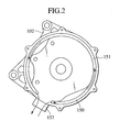
- Fig. 2 is a longitudinal sectional view of the alternator shown in Fig. 1
- Fig. 3 is a perspective view of a part around a regulator in a state where the rear cover is removed
- Fig. 4 is a side elevation of the alternator shown in Fig. 1, in a state where a rear cover is removed
- Fig. 5 is a circuit diagram of the regulator.
- An alternator 100 for a vehicle which is also referred to as the automotive alternator, includes a center housing 102, a front housing 103 behind a pulley, a rear housing 104 on a side opposite to the side of the pulley, and a rear cover 110.
- the front housing 103 is formed by aluminum die cast.
- the front housing 103 holds a front bearing 132, and a rotor shaft 101 is supported in the front bearing 132.
- the center housing 102 is formed by aluminum die cast.
- the center housing 102 holds a rear bearing 134, and the rotor shaft 101 is supported in the rear bearing 134.
- a stator 105 is held on the inner circumference of the center housing 102.
- a coolant path 150 through which a coolant flows is formed inside the center housing 102 and inside the rear housing 104.
- a pulley 130 is mounted on a front end part of the rotor shaft 101, and slip rings 128 are mounted on a rear end part of the rotor shaft 101.
- the pulley 130 is connected to a pulley mounted on the crankshaft of an engine by a belt.
- a rotor 107 is mounted on a middle part of the rotor shaft 101.
- a pair of wedge-shaped claw poles 108 is formed in the circumference of the rotor 107.
- the center housing 102 is provided with a built-in stator core 170.
- a small gap is defined between the inner circumference of the stator core 170 and the surfaces of the claw poles 108 of the rotor 107. Teeth and slots are arranged on the stator core 170, and stator coils 106 for three phases are embedded in the slots of the stator core 105.
- a field coil 109 is formed in a central part of the rotor 107. Supplying a dc current to the field coil 109 through brushes 121 and the slip rings 128 magnetizes the claw poles 108. Three-phase induced voltage is generated in the stator coils 106 when the rotor 107 is driven for rotation by the engine.
- a regulator 120 for regulating the voltage of output, a brush holder 122 and a rectifier 124 for rectifying generated current are fastened to the rear housing 104 and are covered with the rear cover 110.
- the regulator 120 includes a chip and the like formed on a thin substrate.
- a heatsink 127 having the shape of a flat plate is disposed so as to be in surface contact with the back surface of the substrate.
- the regulator 120 and the heatsink 127 are held by a holder 122 formed integrally with the brushes 121 and a connector 126 for connection with the vehicle side.
- the regulator 120 and the heatsink 127 are fastened to the rear housing or the center housing with fastening devices 136.
- the rear housing 104 is provided with mounting projections 138 provided with an internal thread. Mounting bosses formed on the heatsink 127 are set on the mounting projections 138 and the heatsink 127 is fastened t the rear housing 104 with long bolts 136 serving as the fastening devices.
- the heatsink 127 of the regulator 120 is spaced from the rear housing 104 by a distance corresponding to the sum of the respective heights of the mounting projections 138 and the bosses of the heatsink 127. Also, the heatsink 127 is spaced from the rear cover 110. Heat is transferred from the heatsink 127 of the regulator 120 through the fastening devices 136 to the rear housing 104.
- the fastening devices 136 are formed of iron or brass having a heat conductivity ⁇ of 30 W/m ⁇ K or above.
- the rear housing 104 and the rear cover 110 are formed of aluminum, i.e., a material having good heat conductance, by die cast.
- the rear housing 104 and the rear cover 110 may be formed of aluminum plates by press molding instead of by aluminum die cast.
- the regulator 120 and the heatsink 127 may be fixedly held in place by any suitable holding means instead of by the combination of the long bolts and the mounting projections, provided that the holding means is capable of holding the regulator 120 and the heatsink 127 apart from the rear housing 104 and the rear cover 110 and of efficiently transmitting heat generated by the regulator 120 to the rear housing.
- the regulator 120, the rectifier 124 for rectifying generated current, and the brushes 121 for supplying a field current to the rotor are arranged substantially in the same plane.
- the center housing 102 holds the rear bearing 134, on a side opposite to the pulley, on the inner side of the rear cover 110 covering the regulator 120, the rectifier 124 and the brushes 121.
- heat generated by the regulator 120 flows to the heatsink 127 and is dissipated through the fastening devices 136 into the coolant flowing through the coolant path 150. Since heat is dissipated through the fastening devices 136, heat can be efficiently transferred from the regulator 120 to the rear housing 104 even if the holder 122 formed of a resin is held between the heatsink 127 and the rear housing 104.
- the coolant path 150 formed in the alternator to allow the coolant to flow through the alternator has a cyclic channel 151 (see Fig. 2) axially extending in the center housing.
- One of the opposite ends or both the opposite ends of the cyclic channel 151 are open, and the open end or the open ends are covered with the rear housing 104 to form a closed water path.
- only the rear end of the coolant path is open.
- the coolant path 150 communicates with an outlet and inlet coolant pipe 152 formed in the side wall of the center housing 102.
- the heatsink of the regulator 120 for controlling the voltage of output is fastened to the rear housing 104 forming part of the coolant path 150 by the fastening devices 136, heat generated by the regulator 120 is transferred through the fastening devices 137 to the rear housing 104 and is dissipated into the coolant.
- the coolant path 150 communicates with an engine coolant circulation system by means of the outlet and inlet coolant pipe 152 formed in the side wall of the center housing 102.
- a radiator, a thermostat and a pump are connected to the engine coolant circulation system. Heat generated by the alternator is absorbed by the coolant flowing through the engine coolant circulation system and is dissipated through the radiator by heat exchange.
- the regulator 120 is held by a regulator holder 122 formed integrally with the brushes 121 and the connector 126 for connection with the vehicle side.
- the regulator 120, the rectifier 124 for rectifying generated current and the brushes 121 for supplying current to the rotor are disposed substantially at the same axial position, i.e., substantially in the same plane.
- a rectification circuit includes diodes 125.
- the brush holder is held fixedly between the heatsink 127 of the regulator 120, and the rear housing 104.
- the regulator 120 regulates the field current to maintain the voltage of the dc current produced by rectifying an alternating current by the rectifier 124 at a fixed voltage on the order of 14.3 V to charge a battery.
- the positive diode fins are connected to the positive terminal of the battery.
- the potential of negative diode fins are equal to that of the alternator 100.
- the negative diode fins are connected electrically to the negative terminal of the battery.
- the rectifier including the diodes is a full-wave rectifier capable of rectifying the voltage of an alternate current induced in the stator coils 106 into a dc voltage.
- a current produced in the stator coils 106 flows in the stator 105 of the alternator and the thus produced current is rectified by the rectifier 124 to provide a direct current.
- the regulator 120 regulates the field current supplied to the rotor 107 to create a magnetic field.
- the outer circumference of the stator 105 is in contact with the center housing 102.
- the center housing 102 is formed of a material having good heat conductance, a heat conductivity of 80 W/m ⁇ K or above, such as aluminum, by die cast.
- the coolant flows through the coolant path 150 formed in the wall of the center housing 102. Accordingly, most part of heat generated by the stator coil 106 can be dissipated into the coolant.
- the present invention covers the regulator 120 and the rectifier 124 with the cover 110 formed of a material having good heat conductance of 80 W/m ⁇ K or above, such as aluminum, by die cast.
- the cover 110 has a peripheral part attached to the rear housing 104 formed of a material having good heat conductance, a heat conductivity of 80 W/m ⁇ K or above, such as aluminum, by die casting and fixed to the center housing 102.
- the regulator 120 is in thermal contact with the heatsink 127 fixed to the rear housing 104 and formed of a material having good heat conductance, a heat conductivity of 80 W/m ⁇ K or above. Thus, heat generated by the regulator 120 can be transferred to the center housing 102 and can be dissipated into the coolant.
- the housings 102, 103 and 104 holding the stator 105 and the rotor 107 are formed of metals having good neat conductance, a hat conductivity of 80 W/m ⁇ K or above. Most part of heat generated by the stator coils 106 is transferred to the coolant flowing through the housings.
- the rear cover 110 covering the regulator 120, the regulator holder 122 and the rectifier 124 is formed of a metal having good heat conductance, a heat conductivity of 80 W/m ⁇ K or above. Most part of the peripheral part of the rear cover 110 is in metal contact with the housing.
- the respective temperatures of the regulator 120 and the rectifier 124 are not dominated by the high temperature of the ambient air and the radiant heat radiated by high-temperature parts even when the automotive alternator is exposed to a high-temperature atmosphere.
- the alternator in which the heatsink of the regulator is in close contact with the housing provided with the coolant path, is subject to restrictions on the arrangement of the regulator, the brushes and the rectifier, which sometimes causes structural inconvenience and problems with assembling work.
- the heat generated by the regulator is transferred through the fastening devices 136. Therefore, the regulator 120 does not need to be held in close contact with the housing and hence the freedom of placing the regulator, the brushes and the rectifier is improved.
- Fig. 6 is a graph showing the results of experiments performed to examine the respective cooling abilities of an air-cooled system that cools the regulator by air and a water-cooled system that cools the regulator through the fastening devices by water. Temperature difference between a heatsink cooled by the air-cooled system and a heatsink cooled by the water-cooled system is known from Fig. 6. Experiments for the air-cooled system used a holder that can be used also in an air-cooled alternator of a regulator. The temperature difference known from the graph represents the effect of cooling using the fastening devices 136. The regulator case cooled by the water-cooled system using the fastening devices of the present invention was kept at temperatures not higher than 70°C.
- the regulator case cooled by the air-cooled system was heated at high temperatures in the range of 90 to 120°C.
- the regulator can be cooled with reliability by the water-cooled system using the fastening devices, and the water-cooled system improves the freedom of placement.
- the automotive alternator 100 may be provided with only the front housing 103, the rear housing 104 and the rear cover 110, and the center housing may be omitted.
- the regulator 120 is held on the rear housing 104.
- the coolant path through which the coolant flows is provided in the walls of the front housing 103 and the rear housing 104. Omission of the center housing reduces the number of parts.
- Fig. 7 is a longitudinal sectional view of a liquid-cooled automotive alternator in a second embodiment according to the present invention.
- a holder formed integrally with brushes 121 and a connector 126 for connection with the vehicle side holds a regulator 120.
- a heatsink 127 included in the regulator 120 is fastened to a rear housing 104 by fastening devices 136.
- the regulator 120, a rectifier 124 and the brushes 121 are disposed substantially in the same plane.
- the effect of the second embodiment is similar to that of the first embodiment.
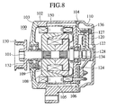
- Fig. 8 is a longitudinal sectional view of a liquid-cooled automotive alternator in a third embodiment according to the present invention
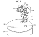
- Fig. 9 is a perspective view of a part around a regulator of the automotive alternator shown in Fig. 8, in which a rear cover is removed.
- a regulator 120 is disposed between a holder 122 and a rear housing 104, and a heatsink 127 included in the regulator 120 is fastened to a rear housing 104 by fastening devices 136.
- the effect of the third embodiment is similar to those of the foregoing embodiments.
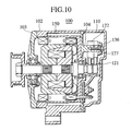
- Fig. 10 is a longitudinal sectional view of a liquid-cooled automotive alternator in a fourth embodiment according to the present invention
- Fig. 11 is a perspective view of a part around a regulator of the automotive alternator shown in Fig. 10, in which a rear cover is removed.
- An automotive alternator 100 in the fourth embodiment has a front housing 103, a rear housing 104 and a rear cover 110.
- a regulator holder 122 formed integrally with brushes 121 and a connector 126 for connection with the vehicle side holds a regulator 120.
- the regulator 120 and the brushes 121 are arranged in the axial direction of the alternator with the regulator 120 disposed at the outermost axial end.
- a heatsink 127 and fastening devices 136 are formed of materials respectively having good heat conductance. Heat generated by the regulator 120 is efficiently transferred to the center housing 102 and is dissipated by a coolant.
- the axial arrangement of the brushes 121 and the regulator 120 reduces the circumferential area of the holder 122 holding the regulator 120 to improve the freedom of placement of other parts in the rear cover 110.
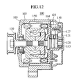
- Fig. 12 is a longitudinal sectional view of a liquid-cooled automotive alternator in a fifth embodiment according to the present invention.
- the fifth embodiment differs from the foregoing embodiments in that slip rings 128 of a rotor are disposed on the inner side of a rear bearing 135 on a side opposite to the side of a pulley.
- this arrangement of the slip rings 128 enables disposing a regulator 120 and a rectifier closer to a center housing 102, so that heat generated by the regulator 120 and the rectifier 124 can be effectively transferred to the center housing 102 for cooling.
- the regulator and the heatsink for the regulator are fixed at a position apart from the housing and the cover by the fastening devices formed of a material having good heat conductance.
- Most part of the heat generated by the regulator is transferred to the coolant flowing through the housing. Therefore, the temperature of the regulator entirely covered with the cover and the housing is dependent mainly on the temperature of the coolant. Therefore, even when the automotive alternator is exposed to a high-temperature atmosphere for a long time, the temperatures of the regulator is not dominated by the ambient temperature and radiant heat radiated by the adjacent high-temperature parts. Thus, the automotive alternator has a stable cooling effect.
- the freedom of placement of the regulator is improved.
Landscapes
- Engineering & Computer Science (AREA)
- Power Engineering (AREA)
- Motor Or Generator Cooling System (AREA)
- Synchronous Machinery (AREA)
Applications Claiming Priority (2)
| Application Number | Priority Date | Filing Date | Title |
|---|---|---|---|
| JP2002001287 | 2002-01-08 | ||
| JP2002001287A JP3690348B2 (ja) | 2002-01-08 | 2002-01-08 | 自動車用交流発電機 |
Publications (3)
| Publication Number | Publication Date |
|---|---|
| EP1326321A2 true EP1326321A2 (fr) | 2003-07-09 |
| EP1326321A3 EP1326321A3 (fr) | 2005-03-16 |
| EP1326321B1 EP1326321B1 (fr) | 2006-12-13 |
Family
ID=19190599
Family Applications (1)
| Application Number | Title | Priority Date | Filing Date |
|---|---|---|---|
| EP03000059A Expired - Lifetime EP1326321B1 (fr) | 2002-01-08 | 2003-01-07 | Alternateur pour véhicule |
Country Status (4)
| Country | Link |
|---|---|
| US (1) | US6864603B2 (fr) |
| EP (1) | EP1326321B1 (fr) |
| JP (1) | JP3690348B2 (fr) |
| DE (1) | DE60310275T2 (fr) |
Cited By (3)
| Publication number | Priority date | Publication date | Assignee | Title |
|---|---|---|---|---|
| WO2005064773A1 (fr) * | 2003-12-30 | 2005-07-14 | Robert Bosch Gmbh | Unite modulaire de regulation et generateur |
| FR2969411A1 (fr) * | 2010-12-20 | 2012-06-22 | Valeo Equip Electr Moteur | Dispositif regulateur de tension pour une machine electrique tournante, palier d'une telle machine equipe d'un tel dispositif et une telle machine comportant un tel palier |
| FR2969413A1 (fr) * | 2010-12-20 | 2012-06-22 | Valeo Equip Electr Moteur | Dispositif regulateur de tension pour une machine electrique tournante, palier d'une telle machine equipe d'un tel dispositif et une telle machine comportant un tel palier |
Families Citing this family (7)
| Publication number | Priority date | Publication date | Assignee | Title |
|---|---|---|---|---|
| JP4994621B2 (ja) * | 2005-08-23 | 2012-08-08 | 株式会社デンソー | 車両用交流発電機の電圧制御装置 |
| US7642539B2 (en) | 2005-12-13 | 2010-01-05 | Macronix International Co., Ltd. | Thin film fuse phase change cell with thermal isolation pad and manufacturing method |
| JP4340305B2 (ja) * | 2007-06-08 | 2009-10-07 | 三菱電機株式会社 | 車両用交流発電機 |
| US8339000B2 (en) * | 2010-01-21 | 2012-12-25 | Remy Technologies, Llc | Electric machine with isolated ground electronics |
| JP5844629B2 (ja) * | 2011-12-13 | 2016-01-20 | 住友重機械工業株式会社 | ギヤモータ |
| JP5942967B2 (ja) | 2013-11-29 | 2016-06-29 | 株式会社デンソー | 駆動装置 |
| US10566873B2 (en) * | 2014-09-25 | 2020-02-18 | Hitachi Automotive Systems, Ltd. | Rotating electrical machine having means to secure plating to cover a flow passage |
Family Cites Families (15)
| Publication number | Priority date | Publication date | Assignee | Title |
|---|---|---|---|---|
| US4221982A (en) * | 1978-07-31 | 1980-09-09 | General Motors Corporation | Liquid cooled rectified-alternating current generator |
| US4980588A (en) * | 1986-02-14 | 1990-12-25 | Mitsubishi Denki Kabushiki Kaisha | Water-cooled vehicle generator |
| JP2842500B2 (ja) * | 1993-04-09 | 1999-01-06 | 三菱電機株式会社 | 車両用発電機 |
| JP2829234B2 (ja) | 1993-12-28 | 1998-11-25 | 三菱電機株式会社 | 車両用交流発電機 |
| FR2732521B1 (fr) * | 1995-03-27 | 1997-04-25 | Valeo Equip Electr Moteur | Alternateur pour vehicule automobile muni d'un regulateur de tension dont les bornes de raccordement sont recues dans un logement etanche |
| EP0816147A3 (fr) * | 1996-07-02 | 2000-03-08 | Denso Corporation | Appareil rotatif et de chauffage pour véhicule |
| DE19705228A1 (de) * | 1997-02-12 | 1998-08-13 | Bosch Gmbh Robert | Elektrische Maschine, vorzugsweise Drehstromgenerator mit Gleichrichter-Baueinheit |
| US5949166A (en) * | 1997-09-25 | 1999-09-07 | Denso Corporation | Rectifying apparatus for an automotive AC generator |
| JP3877894B2 (ja) * | 1999-01-13 | 2007-02-07 | 三菱電機株式会社 | 車両用ブラシレス交流発電機 |
| JP2000245111A (ja) | 1999-02-22 | 2000-09-08 | Hitachi Ltd | 車両用交流発電機 |
| GB2348548B (en) | 1999-04-01 | 2003-10-15 | Delphi Tech Inc | Electric motor or generator |
| JP3499155B2 (ja) * | 1999-05-27 | 2004-02-23 | 三菱電機株式会社 | スタータ |
| FR2794299B1 (fr) * | 1999-05-31 | 2001-06-29 | Valeo Equip Electr Moteur | Porte-balais a composant de commande pour alternateur de vehicule automobile |
| GB2355860A (en) | 1999-10-28 | 2001-05-02 | Delphi Tech Inc | Heat shielding electric motor or generator electric components |
| JP3949369B2 (ja) * | 2000-10-20 | 2007-07-25 | 三菱電機株式会社 | 車両用交流発電機 |
-
2002
- 2002-01-08 JP JP2002001287A patent/JP3690348B2/ja not_active Expired - Fee Related
-
2003
- 2003-01-07 DE DE60310275T patent/DE60310275T2/de not_active Expired - Lifetime
- 2003-01-07 EP EP03000059A patent/EP1326321B1/fr not_active Expired - Lifetime
- 2003-01-08 US US10/337,842 patent/US6864603B2/en not_active Expired - Fee Related
Cited By (7)
| Publication number | Priority date | Publication date | Assignee | Title |
|---|---|---|---|---|
| WO2005064773A1 (fr) * | 2003-12-30 | 2005-07-14 | Robert Bosch Gmbh | Unite modulaire de regulation et generateur |
| CN100566083C (zh) * | 2003-12-30 | 2009-12-02 | 罗伯特·博世有限公司 | 调节器结构单元和发电机 |
| US7872382B2 (en) | 2003-12-30 | 2011-01-18 | Robert Bosch Gmbh | Regulator unit and generator |
| FR2969411A1 (fr) * | 2010-12-20 | 2012-06-22 | Valeo Equip Electr Moteur | Dispositif regulateur de tension pour une machine electrique tournante, palier d'une telle machine equipe d'un tel dispositif et une telle machine comportant un tel palier |
| FR2969413A1 (fr) * | 2010-12-20 | 2012-06-22 | Valeo Equip Electr Moteur | Dispositif regulateur de tension pour une machine electrique tournante, palier d'une telle machine equipe d'un tel dispositif et une telle machine comportant un tel palier |
| WO2012085423A3 (fr) * | 2010-12-20 | 2012-12-13 | Valeo Equipements Electriques Moteur | Dispositif regulateur de tension pour une machine electrique tournante, palier d'une telle machine equipe d'un tel dispositif et une telle machine comportant un tel palier |
| US9484787B2 (en) | 2010-12-20 | 2016-11-01 | Valeo Equipments Electriques Moteur | Voltage regulator device for rotary electric machine, bearing for rotary electric machine and rotary electric machine comprising such bearing |
Also Published As
| Publication number | Publication date |
|---|---|
| US6864603B2 (en) | 2005-03-08 |
| DE60310275D1 (de) | 2007-01-25 |
| EP1326321B1 (fr) | 2006-12-13 |
| JP3690348B2 (ja) | 2005-08-31 |
| DE60310275T2 (de) | 2007-05-31 |
| EP1326321A3 (fr) | 2005-03-16 |
| JP2003204656A (ja) | 2003-07-18 |
| US20030127920A1 (en) | 2003-07-10 |
Similar Documents
| Publication | Publication Date | Title |
|---|---|---|
| EP0480484B1 (fr) | Générateur à courant alternatif, monté sur véhicule | |
| US4955944A (en) | Rotating electric machine | |
| CN100533923C (zh) | 用于机动车的旋转电机 | |
| US6218747B1 (en) | Car AC generator | |
| EP1394925B1 (fr) | Alternateur de véhicule avec redresseur monté sur un dissipateur de chaleur à ailettes de refroidissement | |
| EP1193837A2 (fr) | Alternateur pour véhicules | |
| CN102055280B (zh) | 无刷旋转电机 | |
| JP3750851B2 (ja) | 車両用交流発電機 | |
| EP1146626B1 (fr) | Structure de refroidissement d'un alternateur de véhicule | |
| US9166461B2 (en) | Automotive alternator having a heat dissipating plate | |
| JPH0946970A (ja) | ウォータポンプ一体型車両用回転電機 | |
| US6864603B2 (en) | Alternator for vehicle | |
| KR100874317B1 (ko) | 차량용 교류 발전기 | |
| JP2010514405A (ja) | 回転電気機械の電流を整流するための装置、およびこのような装置を有する回転電気機械 | |
| JP2004357451A (ja) | 車両用交流発電機 | |
| JP4278643B2 (ja) | 車両用回転電機 | |
| JP3913903B2 (ja) | 車両用交流発電機 | |
| JP4184871B2 (ja) | 液冷式回転電機 | |
| CN111869057A (zh) | 带电刷的旋转电机 | |
| JP4023489B2 (ja) | 自動車用交流発電機 | |
| JP4258909B2 (ja) | 車両用交流発電機 | |
| JP2005224044A (ja) | 車両用発電電動装置 | |
| JPH04244770A (ja) | 車両用交流発電機 | |
| JP2000245111A (ja) | 車両用交流発電機 | |
| JPH03178539A (ja) | 車両用交流発電機 |
Legal Events
| Date | Code | Title | Description |
|---|---|---|---|
| PUAI | Public reference made under article 153(3) epc to a published international application that has entered the european phase |
Free format text: ORIGINAL CODE: 0009012 |
|
| AK | Designated contracting states |
Designated state(s): AT BE BG CH CY CZ DE DK EE ES FI FR GB GR HU IE IT LI LU MC NL PT SE SI SK TR |
|
| AX | Request for extension of the european patent |
Extension state: AL LT LV MK RO |
|
| PUAL | Search report despatched |
Free format text: ORIGINAL CODE: 0009013 |
|
| AK | Designated contracting states |
Kind code of ref document: A3 Designated state(s): AT BE BG CH CY CZ DE DK EE ES FI FR GB GR HU IE IT LI LU MC NL PT SE SI SK TR |
|
| AX | Request for extension of the european patent |
Extension state: AL LT LV MK RO |
|
| 17P | Request for examination filed |
Effective date: 20050707 |
|
| AKX | Designation fees paid |
Designated state(s): DE FR GB IT |
|
| GRAP | Despatch of communication of intention to grant a patent |
Free format text: ORIGINAL CODE: EPIDOSNIGR1 |
|
| GRAS | Grant fee paid |
Free format text: ORIGINAL CODE: EPIDOSNIGR3 |
|
| GRAA | (expected) grant |
Free format text: ORIGINAL CODE: 0009210 |
|
| RAP1 | Party data changed (applicant data changed or rights of an application transferred) |
Owner name: HITACHI, LTD. |
|
| AK | Designated contracting states |
Kind code of ref document: B1 Designated state(s): DE FR GB IT |
|
| REG | Reference to a national code |
Ref country code: GB Ref legal event code: FG4D |
|
| REF | Corresponds to: |
Ref document number: 60310275 Country of ref document: DE Date of ref document: 20070125 Kind code of ref document: P |
|
| ET | Fr: translation filed | ||
| PLBE | No opposition filed within time limit |
Free format text: ORIGINAL CODE: 0009261 |
|
| STAA | Information on the status of an ep patent application or granted ep patent |
Free format text: STATUS: NO OPPOSITION FILED WITHIN TIME LIMIT |
|
| 26N | No opposition filed |
Effective date: 20070914 |
|
| PGFP | Annual fee paid to national office [announced via postgrant information from national office to epo] |
Ref country code: FR Payment date: 20120202 Year of fee payment: 10 |
|
| PGFP | Annual fee paid to national office [announced via postgrant information from national office to epo] |
Ref country code: DE Payment date: 20120104 Year of fee payment: 10 |
|
| PGFP | Annual fee paid to national office [announced via postgrant information from national office to epo] |
Ref country code: GB Payment date: 20120104 Year of fee payment: 10 Ref country code: IT Payment date: 20120111 Year of fee payment: 10 |
|
| GBPC | Gb: european patent ceased through non-payment of renewal fee |
Effective date: 20130107 |
|
| REG | Reference to a national code |
Ref country code: FR Ref legal event code: ST Effective date: 20130930 |
|
| PG25 | Lapsed in a contracting state [announced via postgrant information from national office to epo] |
Ref country code: DE Free format text: LAPSE BECAUSE OF NON-PAYMENT OF DUE FEES Effective date: 20130801 |
|
| REG | Reference to a national code |
Ref country code: DE Ref legal event code: R119 Ref document number: 60310275 Country of ref document: DE Effective date: 20130801 |
|
| PG25 | Lapsed in a contracting state [announced via postgrant information from national office to epo] |
Ref country code: FR Free format text: LAPSE BECAUSE OF NON-PAYMENT OF DUE FEES Effective date: 20130131 Ref country code: GB Free format text: LAPSE BECAUSE OF NON-PAYMENT OF DUE FEES Effective date: 20130107 |
|
| PG25 | Lapsed in a contracting state [announced via postgrant information from national office to epo] |
Ref country code: IT Free format text: LAPSE BECAUSE OF NON-PAYMENT OF DUE FEES Effective date: 20130107 |