EP1326546B1 - Joint pour trocart fixe - Google Patents
Joint pour trocart fixe Download PDFInfo
- Publication number
- EP1326546B1 EP1326546B1 EP01987680A EP01987680A EP1326546B1 EP 1326546 B1 EP1326546 B1 EP 1326546B1 EP 01987680 A EP01987680 A EP 01987680A EP 01987680 A EP01987680 A EP 01987680A EP 1326546 B1 EP1326546 B1 EP 1326546B1
- Authority
- EP
- European Patent Office
- Prior art keywords
- housing
- reduction member
- seal
- rim
- trocar
- Prior art date
- Legal status (The legal status is an assumption and is not a legal conclusion. Google has not performed a legal analysis and makes no representation as to the accuracy of the status listed.)
- Expired - Lifetime
Links
Images


Classifications
-
- A—HUMAN NECESSITIES
- A61—MEDICAL OR VETERINARY SCIENCE; HYGIENE
- A61B—DIAGNOSIS; SURGERY; IDENTIFICATION
- A61B17/00—Surgical instruments, devices or methods
- A61B17/34—Trocars; Puncturing needles
- A61B17/3462—Trocars; Puncturing needles with means for changing the diameter or the orientation of the entrance port of the cannula, e.g. for use with different-sized instruments, reduction ports, adapter seals
Definitions
- the present disclosure relates to a mechanism for controlling the operable area of a passageway defined in a valve assembly of a trocar. More particularly, the present disclosure relates to a diameter reduction mechanism that is removably positionable over the passageway of the trocar to restrict the movement of small diameter surgical instruments to a reduced operable area of the passageway without sealing with the trocar and pivot clear of the passageway to accommodate large diameter surgical instruments.
- US-A-5,868,714 discloses a reducer cap for a trocar assembly, which cap includes a wiper seal of elastic material for maintaining abdominal pressure during use of small diameter surgical tools.
- Trocar valve assemblies are configured to provide a fluid tight sealing system before, during, and after a surgical instrument is entered through the trocar during minimally invasive surgical procedures.
- Sealing systems such as a valve assembly for a passageway defined by a trocar connected with a cannula include an outer seal which can be fixed or floating, in combination with additional inner seals.
- Fixed outer seals are limited by their ability to sustain a seal when smaller surgical instruments are moved off-axis, away from and generally parallel to the central longitudinal axis, towards the inside circumference of the cannula. Fixed seals are also limited by their ability to sustain their integrity when small diameter surgical tool angulation is employed.
- Devices to restrict the diameter of a passageway in a trocar housing generally require a complex additional mechanism to be positioned on the proximal end of the trocar housing that restricts the range of motion of small surgical instruments and include additional seals or replace seals of the valve assembly with seals configured for small surgical instruments.
- These diameter reducing devices typically require the disassembly and assembly of the proximal end of the trocar to adjust for the varying sizes of diameter reduction devices.
- a diameter reduction mechanism for assisting the valve assembly of a trocar in maintaining a seal.
- the diameter reduction mechanism includes a housing and a movable limiter.
- the limiter is diametrically positionable over the passageway to control the parallel off-axis and angular movements of smaller diameter surgical instruments.
- the limiter includes a locking mechanism and a pivot. The locking mechanism is adapted for use by a surgeon to readily lock the limiter in position over the passageway and to unlock and move the limiter clear of the passageway. Once the limiter is clear of the passageway, larger diameter surgical instruments are freely positionable within the passageway without any further adjustments by the operator.
- the present disclosure contemplates the introduction into a body of a patient a trocar adapted for receiving all types of surgical instruments including clip appliers, graspers, dissectors, retractors, staplers, laser fibers, endoscopes, as well as electrosurgical cutting, coagulating, and ablation devices, and the like. All such objects are referred to herein as "instruments”.
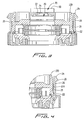
- Trocar assembly 100 includes valve assembly 120, end cap 130, and cannula (not shown).
- Trocar assembly 100 defines a passageway 150 aligned with a central longitudinal axis-X. Passageway 150 defines a first operable area.
- Valve assembly 120 is configured to provide a seal between a cavity formed in the patient and the outside atmosphere during and subsequent to insertion of an instrument through the cannula.
- Diameter reduction mechanism for fixed trocar seal 10 includes a housing 20 and a limiter 50.
- Housing 20, in one preferred embodiment is an integral and proximal portion of valve assembly 120 of trocar 100.
- housing 20 is a tubular shaped ring adapted for being removably connected to a proximal end of valve assembly 120.
- Housing 20 includes a tubular wall 26 having a distal end portion 22 and a proximal end portion 24 aligned with the longitudinal axis-X.
- distal end portion 22 of tubular wall 26 includes an inwardly and radially extending protuberance 23 configured to engagingly mate and lock with an annular lip 133 positioned on end cap 130 of valve assembly 120.
- proximal end portion 24 includes a receptacle 25 having a pair of opposed notches 27 configured for the pivoting of limiter 50 and a diametrically opposed lip 28 positioned on wall 26.
- Lip 28 has an arcuate shaped portion extending outwardly and radially from wall 26 with a distal facing generally flat portion.
- diameter reduction mechanism 10 in a first position includes housing 20 lockingly engaged with valve assembly 120 and limiter or reduction member 50 extending diametrically over passageway 150 and valve assembly 120.
- Limiter 50 includes a first end 52 being pivotally connected to a receptacle 25 of housing 20 and a second end 54 being engaged and locked with lip 28.
- An axis-Z is defined perpendicular to limiter 50 and axis-Y that intersects axis-X.
- Limiter 50 has an elongate planar beam shape having a thickness in the direction of axis-X and a width in the direction of axis-Z. The width of limiter 50 can vary, but is approximately less than or equal to the diameter of passageway 150.
- a hole or opening 71 is centrally positioned on limiter 50 and aligned with the longitudinal axis-X. Limiter 50 also includes an annular recess 59 positioning hole 71 distal to first end 52 and second end 54 such that a proximal side of a rim 72 of hole 71 is positioned approximately equal to or below the proximal edge of valve assembly 120.
- first end 52 can include interfaces such as a hinge, a threaded connection, or a slide, such that the limiter 50 can pivot about notch 27 of receptacle 25.
- first end 54 includes a pair pins 55 perpendicular to axis-Y positionable within notches 27. Pins 55 have a controlled tolerance to fit tightly within notches 27 for a pure rotational hinge type movement or notches 27 can include a predetermined amount of play or bias such that limiter 50 can translate a controlled distance along axis-Y, for example, or pivot angularly within a plane Z-Y formed by the intersection of axes Z and Y.
- second end 54 includes a locking mechanism 60 having a first cantilevered element 62 extending along axis-Y with a second cantilevered element 64 and a third cantilevered element or locking element 66 extending distally therefrom and generally parallel to longitudinal axis-X.
- a distal end of element 66 includes a radially inwardly extending protuberance 67 configured for engagingly interfacing with lip 28 to lock limiter 50 in the first position.
- a fillet 63 extends between an edge 61 of element 62 and a distal end edge 65 of element 64. Fillet 63 is ergonomically configured for the positioning of a limb or portion of a limb of a surgeon for the proximal movement or flexing of second end 54 to disengage protuberance 67 from lip 28.
- Limiter 50 includes an interior portion 70 having a proximal first rim 72 and a distal second rim 74 defining hole 71 as well as an annular portion 78.
- Rim 72 has a conical shape with a distally decreasing inside diameter and rim 74 has a conical shape with a distally increasing diameter.
- the conical shapes of rims 72 and 74 are advantageously configured to support a limited degree of small surgical instrument angulation.
- Hole 71 is aligned with the longitudinal axis-X in the first position and less than the inside diameter of passageway 150 by a predetermined amount, depending upon the desired application. Thus, hole 71 reduces the first operable area to a second operable area less than the first operable area. It is envisioned that diameter reduction mechanism for fixed trocar seal 10 can be provided in a variety of reducing diameters in a kit configuration having multiple limiters 50 and/or mechanisms 10 and be readily removed and replaced as an assembly without interrupting the integrity of the valve assembly.
- interior portion 70 includes an annular channel 76 extending proximally from the distal side of limiter 50.
- Channel 76 is in apposition with rim 74 and defines rim 74 as a distally extending cantilevered element that provides a controlled degree of flexing or bias by rim 74 to urge instruments towards the central longitudinal axis.
- Annular portion 78 extends distally from interior portion 70.
- Annular portion 78 has a distal end 79 configured for seating on a rim 139 of a proximal end of end cap 130.
- Rim 139 defines a proximal portion of passageway 150 in conjunction with annular portion 78 in the first position.
- Annular portion 78 defines an inside diameter approximately equivalent to the proximal portion of passageway 150 defined by end cap 130.
- limiter 50 in the first position is configured as a cross beam supported on ends 54 and 52 by housing 20 and by the positioning of annular portion 78 in direct contact with rim 139 of end cap 130.
- Annular portion 78 provides structural support for limiter 50 and it precludes the misalignment of instruments while providing a non-sealing interface with passageway 150.
- Limiter 50 is movably positioned on housing 20 such that when the surgeon desires to use instruments larger than the diameter of hole 71, the limiter 50 can be readily pivoted out of the first position over passageway 150 by using the limb or the portion of the limb of the surgeon to pull proximally against fillet 63 or edge 61.
- diameter reduction mechanism for fixed trocar seal 10 is in a second position.
- Limiter 50 in the second position is preferably extending distally and parallel to the longitudinal axis-X, but it may include stops or be biased to a range of positions from extending proximally and generally parallel to the longitudinal axis-X to being parallel to axis-Y, for example.
- limiter 50 can be suitably configured for translation or angular movement with the X-Y plane such that limiter 50 can include a variable circumference configured to be aligned with axis-X that can be integral to or removably attached to limiter 50 to accommodate varying sized instruments without removing limiter 50 or diameter reduction mechanism for fixed trocar seal 10 from the trocar.
- diameter reduction mechanism for fixed trocar seal 10 is positioned over a proximal end of valve assembly 120 of trocar 100 and forwarded distally to engage and lock housing 20 with valve assembly 120.
- Moving limiter 50 accommodates the selective changing of the operable area of passageway 150.
- Limiter 50 in the first position is configured to limit the off axis movements as well as the angulation of small diameter surgical instruments less than or equal to the diameter of hole 71.
- Limiter 50 is adapted to readily accommodate, with a single movement of edge 61 or fillet 63, the movement of limiter 50 from the first position to the second position for the positioning of larger diameter surgical instruments.
- Limiter 50 is adapted for being readily replaced to the first position by the limb of the surgeon positioning second end 54 to suitably engage locking mechanism 60 to retain limiter 50 in the first position.
Landscapes
- Health & Medical Sciences (AREA)
- Surgery (AREA)
- Life Sciences & Earth Sciences (AREA)
- Medical Informatics (AREA)
- Nuclear Medicine, Radiotherapy & Molecular Imaging (AREA)
- Engineering & Computer Science (AREA)
- Biomedical Technology (AREA)
- Heart & Thoracic Surgery (AREA)
- Pathology (AREA)
- Molecular Biology (AREA)
- Animal Behavior & Ethology (AREA)
- General Health & Medical Sciences (AREA)
- Public Health (AREA)
- Veterinary Medicine (AREA)
- Surgical Instruments (AREA)
- Endoscopes (AREA)
Claims (14)
- Joint pour trocart pour utilisation avec un ensemble de trocart, ledit joint comprend:un boîtier (20) apte à être monté sur un ensemble de trocart (100), le boîtier incluant une paroi extérieure définissant un axe longitudinal (X), et des extrémités proximale (24) et distale (22), le boîtier ayant une paroi transversale intérieure (26);un joint interne (10) disposé dans le boîtier généralement aligné avec l'axe longitudinal, le joint interne ayant une ouverture pour la réception étanche d'un objet oblong introduit dans celle-ci; etun élément de réduction (50) monté sur le boîtier et déplaçable relativement au boîtier entre des première et deuxième positions, l'élément de réduction ayant une portion intérieure définissant une ouverture (71) à travers celle-ci, l'ouverture étant généralement alignée avec l'ouverture du joint interne lorsque l'élément de réduction se trouve dans sa première position, et à distance de l'axe longitudinal dans la deuxième position, la portion intérieure dans ladite première position étant dimensionnée pour réduire à un minimum un mouvement latéral de décalage de l'objet oblong pendant la manipulation de l'objet oblong lorsque l'objet oblong est inséré dans et reçu d'une manière étanche par le joint interne, l'élément de réduction incluant en outre une portion annulaire (78) disposée distalement de la portion intérieure, la portion annulaire étant dimensionnée pour venir en prise avec la paroi transversale du boîtier pour supporter l'élément de réduction lorsqu'il se trouve dans sa première position.
- Joint pour trocart selon la revendication 1, incluant un joint extérieur disposé périphériquement par rapport au joint intérieur et dimensionné pour définir une interface d'étanchéité afin de réduire sensiblement à un minimum le passage des gaz d'insufflation à travers le boîtier.
- Joint pour trocart selon la revendication 1, où l'élément de réduction comprend un bord (72,74), le bord définissant l'ouverture, le bord incluant une première portion proximale (72) et une seconde portion distale (74), la première portion proximale définissant une forme conique et un diamètre intérieur diminuant distalement, la deuxième portion distale définissant une forme conique et un diamètre intérieur augmentant distalement.
- Joint pour trocart selon la revendication 3, où au moins une portion (74) du bord définissant l'ouverture est une structure en porte-à-faux, la structure en porte-à-faux incluant un biais, le biais étant configuré pour solliciter des instruments vers l'axe longitudinal central.
- Joint pour trocart selon la revendication 1, où le boîtier comprend une portion d'extrémité proximale, la portion d'extrémité proximale définissant un bord (139), la portion annulaire de l'élément de réduction étant apte à être montée sur le bord de la portion d'extrémité proximale du boîtier, la portion annulaire réalisant une connection non scellée entre le bord de l'ensemble de vanne et l'ouverture dans l'élément de réduction.
- Joint pour trocart selon la revendication 1, où un mécanisme de verrouillage est positionné sur l'élément de réduction, le mécanisme de verrouillage incluant un élément en porte-à-faux s'étendant distalement ayant une portion d'extrémité distale avec une saillie (23), la saillie s'étendant vers l'intérieur et radialement et ayant une surface généralement plate orientée proximalement apte à venir en prise avec une lèvre (133) du boîtier, la lèvre ayant une surface généralement plate orientée distalement.
- Joint pour trocart selon l'une quelconque des revendications précédentes, où le boîtier comprend une paroi tubulaire et est monté sur une extrémité proximale de l'ensemble de vanne de trocart, l'ensemble de vanne ayant au moins un joint fixe incluant le joint interne et définissant un passage longidinal, le passage longitudinal définissant une première zone opérable;
l'élément de réduction ayant une première extrémité, une deuxième extrémité opposée et une portion intérieure, la première extrémité étant reliée d'une manière pivotante au boîtier, la seconde extrémité ayant un mécanisme de verrouillage pour la mise en prise avec le boîtier, l'élément de réduction dans ladite première position étant positionné sur la première zone opérable du passage, la seconde extrémité étant verrouillée avec le boîtier, la connection pivotante permettant le mouvement et dans ladite seconde position étant positionnée à distance de la première zone opérable du passage, l'élément de réduction et le boîtier réalisant une interface non scellée avec l'ensemble de vanne;
un bord (13a) positionné sur la portion intérieure de l'élément de réduction, le bord définissant un trou aligné avec le passage, le trou définissant une deuxième zone opérable plus petite que la première zone opérable du passage. - Joint pour trocart selon la revendication 7, où le boîtier inclut un réceptacle ayant une paire d'encoches (27), et la première extrémité de l'élément de réduction inclut une paire d'axes opposés linéairement alignés (55), les axes étant configurés et dimensionnés pour le positionnement dans les encoches du réceptacle et permettant un mouvement de l'élément de réduction.
- Joint pour trocart selon la revendication 8, où le réceptacle et les axes sont configurés pour supporter la translation de l'élément de réduction dans un plan aligné avec les axes et perpendiculaire à l'axe longitudinal.
- Joint pour trocart selon la revendication 8, où le réceptacle et les axes sont configurés pour supporter le mouvement angulaire de l'élément de réduction dans un plan aligné avec les axes et perpendiculaire à l'axe longitudinal.
- Joint pour trocart selon la revendication 8, où la connection entre le réceptacle et les axes comprend un biais, le biais étant configuré pour solliciter l'élément de réduction vers une première position où le trou est aligné avec le passage.
- Joint pour trocart selon la revendication 7, où le bord définissant le trou dans la portion intérieure présente une première portion proximale et une seconde portion distale, la première portion proximale définissant une forme conique et un diamètre intérieur diminuant distalement, la seconde portion distale définissant une forme conique et un diamètre intérieur augmentant distalement.
- Joint pour trocart selon la revendication 7, où au moins une portion du bord définissant l'ouverture est une structure en porte-à-faux, la structure en porte-à-faux incluant un biais, le biais étant configuré pour solliciter les instruments vers l'axe longitudinal central.
- Joint pour trocart selon la revendication 7, où la portion annulaire présente une extrémité distale, et l'ensemble de vanne comprend un bord proximal, l'extrémité distale de la portion annulaire étant conçue pour être montée sur le bord proximal de l'ensemble de vanne, le bord proximal définissant une portion du passage, la portion annulaire réalisant une extension proximale non scellée du passage ente le bord de l'ensemble de vanne et le trou dans l'élément de réduction.
Applications Claiming Priority (3)
| Application Number | Priority Date | Filing Date | Title |
|---|---|---|---|
| US24166500P | 2000-10-19 | 2000-10-19 | |
| US241665P | 2000-10-19 | ||
| PCT/US2001/045324 WO2002032481A2 (fr) | 2000-10-19 | 2001-10-19 | Joint pour trocart fixe |
Publications (2)
| Publication Number | Publication Date |
|---|---|
| EP1326546A2 EP1326546A2 (fr) | 2003-07-16 |
| EP1326546B1 true EP1326546B1 (fr) | 2009-01-14 |
Family
ID=22911668
Family Applications (1)
| Application Number | Title | Priority Date | Filing Date |
|---|---|---|---|
| EP01987680A Expired - Lifetime EP1326546B1 (fr) | 2000-10-19 | 2001-10-19 | Joint pour trocart fixe |
Country Status (7)
| Country | Link |
|---|---|
| EP (1) | EP1326546B1 (fr) |
| JP (1) | JP4080867B2 (fr) |
| AU (2) | AU2002244338B2 (fr) |
| CA (1) | CA2425146C (fr) |
| DE (1) | DE60137439D1 (fr) |
| ES (1) | ES2319869T3 (fr) |
| WO (1) | WO2002032481A2 (fr) |
Families Citing this family (1)
| Publication number | Priority date | Publication date | Assignee | Title |
|---|---|---|---|---|
| DE3143605A1 (de) | 1981-11-03 | 1983-05-11 | MTU Motoren- und Turbinen-Union München GmbH, 8000 München | "adiabatischer motor" |
Family Cites Families (5)
| Publication number | Priority date | Publication date | Assignee | Title |
|---|---|---|---|---|
| DE4239403C3 (de) * | 1992-11-24 | 2001-06-21 | Storz Karl Gmbh & Co Kg | Trokarhülse |
| US5338307A (en) * | 1993-03-09 | 1994-08-16 | Ethicon, Inc. | Adaptor cap for trocar assembly |
| US5820606A (en) * | 1996-06-11 | 1998-10-13 | Origin Medsystems, Inc. | Reusable cannula with disposable seal |
| US5868714A (en) * | 1996-09-16 | 1999-02-09 | Endoscopic Concepts, Inc. | Trocar reducer system |
| DE29717940U1 (de) * | 1997-10-09 | 1997-11-27 | ETB Endoskopische Technik GmbH Berlin, 12555 Berlin | Trokarhülse |
-
2001
- 2001-10-19 CA CA2425146A patent/CA2425146C/fr not_active Expired - Fee Related
- 2001-10-19 ES ES01987680T patent/ES2319869T3/es not_active Expired - Lifetime
- 2001-10-19 WO PCT/US2001/045324 patent/WO2002032481A2/fr not_active Ceased
- 2001-10-19 AU AU2002244338A patent/AU2002244338B2/en not_active Ceased
- 2001-10-19 EP EP01987680A patent/EP1326546B1/fr not_active Expired - Lifetime
- 2001-10-19 DE DE60137439T patent/DE60137439D1/de not_active Expired - Lifetime
- 2001-10-19 AU AU4433802A patent/AU4433802A/xx active Pending
- 2001-10-19 JP JP2002535717A patent/JP4080867B2/ja not_active Expired - Fee Related
Also Published As
| Publication number | Publication date |
|---|---|
| JP4080867B2 (ja) | 2008-04-23 |
| CA2425146C (fr) | 2011-01-18 |
| AU2002244338B2 (en) | 2006-11-02 |
| WO2002032481A2 (fr) | 2002-04-25 |
| JP2004531286A (ja) | 2004-10-14 |
| CA2425146A1 (fr) | 2002-04-25 |
| WO2002032481A3 (fr) | 2002-08-15 |
| AU4433802A (en) | 2002-04-29 |
| WO2002032481A9 (fr) | 2003-04-17 |
| EP1326546A2 (fr) | 2003-07-16 |
| DE60137439D1 (de) | 2009-03-05 |
| ES2319869T3 (es) | 2009-05-14 |
Similar Documents
| Publication | Publication Date | Title |
|---|---|---|
| US20080275406A1 (en) | Fixed trocar seal | |
| EP1324711B1 (fr) | Ensemble valve comprenant une structure de reduction de diametre pour trocart | |
| US8282603B2 (en) | Valve assembly including diameter reduction structure for trocar | |
| EP1520537B1 (fr) | Ensemble de trocar renforcé | |
| EP2179700B1 (fr) | Trocart | |
| EP1520541B1 (fr) | Ensemble d'étanchéité en bec de canard à angles multiples | |
| EP1520544B1 (fr) | Mécanisme de verrouillage d'un instrument pour un trocar | |
| EP1520543B1 (fr) | Robinet encastré à faible encombrement pour un trocart | |
| EP2087846B1 (fr) | Ensemble d'accès avec une valve sphérique | |
| EP2233090A1 (fr) | Dispositif portail chirurgical avec ressort | |
| AU2001296824A1 (en) | Valve assembly including diameter reduction structure for trocar | |
| EP2229897B1 (fr) | Appareil de portail chirurgical incluant un boîtier amovible | |
| EP2664289B1 (fr) | Dispositif d'accès chirurgical comprenant une suspension à cardan coopérant avec un soufflet | |
| CA2482702A1 (fr) | Systeme de blocage rotatif pour trocart | |
| EP2138116B1 (fr) | Ensemble de trocart pour boîtier pouvant se déplacer radialement | |
| AU2004214617B2 (en) | Reinforced seal assembly | |
| CA2482725C (fr) | Capsule a bec de canard orientable | |
| CA2425146C (fr) | Joint pour trocart fixe | |
| AU2002244338A1 (en) | Adaptor cap trocar assembly |
Legal Events
| Date | Code | Title | Description |
|---|---|---|---|
| PUAI | Public reference made under article 153(3) epc to a published international application that has entered the european phase |
Free format text: ORIGINAL CODE: 0009012 |
|
| 17P | Request for examination filed |
Effective date: 20030417 |
|
| AK | Designated contracting states |
Designated state(s): AT BE CH CY DE DK ES FI FR GB GR IE IT LI LU MC NL PT SE TR |
|
| AX | Request for extension of the european patent |
Extension state: AL LT LV MK RO SI |
|
| RBV | Designated contracting states (corrected) |
Designated state(s): DE ES FR GB IE IT |
|
| 17Q | First examination report despatched |
Effective date: 20061017 |
|
| GRAP | Despatch of communication of intention to grant a patent |
Free format text: ORIGINAL CODE: EPIDOSNIGR1 |
|
| GRAS | Grant fee paid |
Free format text: ORIGINAL CODE: EPIDOSNIGR3 |
|
| GRAA | (expected) grant |
Free format text: ORIGINAL CODE: 0009210 |
|
| AK | Designated contracting states |
Kind code of ref document: B1 Designated state(s): DE ES FR GB IE IT |
|
| REG | Reference to a national code |
Ref country code: GB Ref legal event code: FG4D |
|
| REG | Reference to a national code |
Ref country code: IE Ref legal event code: FG4D |
|
| REF | Corresponds to: |
Ref document number: 60137439 Country of ref document: DE Date of ref document: 20090305 Kind code of ref document: P |
|
| REG | Reference to a national code |
Ref country code: ES Ref legal event code: FG2A Ref document number: 2319869 Country of ref document: ES Kind code of ref document: T3 |
|
| PLBE | No opposition filed within time limit |
Free format text: ORIGINAL CODE: 0009261 |
|
| STAA | Information on the status of an ep patent application or granted ep patent |
Free format text: STATUS: NO OPPOSITION FILED WITHIN TIME LIMIT |
|
| 26N | No opposition filed |
Effective date: 20091015 |
|
| PGFP | Annual fee paid to national office [announced via postgrant information from national office to epo] |
Ref country code: ES Payment date: 20121026 Year of fee payment: 12 Ref country code: IT Payment date: 20121024 Year of fee payment: 12 |
|
| PG25 | Lapsed in a contracting state [announced via postgrant information from national office to epo] |
Ref country code: IT Free format text: LAPSE BECAUSE OF NON-PAYMENT OF DUE FEES Effective date: 20131019 |
|
| REG | Reference to a national code |
Ref country code: ES Ref legal event code: FD2A Effective date: 20141107 |
|
| PG25 | Lapsed in a contracting state [announced via postgrant information from national office to epo] |
Ref country code: ES Free format text: LAPSE BECAUSE OF NON-PAYMENT OF DUE FEES Effective date: 20131020 |
|
| REG | Reference to a national code |
Ref country code: FR Ref legal event code: PLFP Year of fee payment: 16 |
|
| PGFP | Annual fee paid to national office [announced via postgrant information from national office to epo] |
Ref country code: IE Payment date: 20160922 Year of fee payment: 16 Ref country code: GB Payment date: 20160928 Year of fee payment: 16 |
|
| PGFP | Annual fee paid to national office [announced via postgrant information from national office to epo] |
Ref country code: FR Payment date: 20160921 Year of fee payment: 16 |
|
| PGFP | Annual fee paid to national office [announced via postgrant information from national office to epo] |
Ref country code: DE Payment date: 20160922 Year of fee payment: 16 |
|
| REG | Reference to a national code |
Ref country code: DE Ref legal event code: R119 Ref document number: 60137439 Country of ref document: DE |
|
| GBPC | Gb: european patent ceased through non-payment of renewal fee |
Effective date: 20171019 |
|
| REG | Reference to a national code |
Ref country code: IE Ref legal event code: MM4A |
|
| REG | Reference to a national code |
Ref country code: FR Ref legal event code: ST Effective date: 20180629 |
|
| PG25 | Lapsed in a contracting state [announced via postgrant information from national office to epo] |
Ref country code: GB Free format text: LAPSE BECAUSE OF NON-PAYMENT OF DUE FEES Effective date: 20171019 Ref country code: DE Free format text: LAPSE BECAUSE OF NON-PAYMENT OF DUE FEES Effective date: 20180501 |
|
| PG25 | Lapsed in a contracting state [announced via postgrant information from national office to epo] |
Ref country code: FR Free format text: LAPSE BECAUSE OF NON-PAYMENT OF DUE FEES Effective date: 20171031 |
|
| PG25 | Lapsed in a contracting state [announced via postgrant information from national office to epo] |
Ref country code: IE Free format text: LAPSE BECAUSE OF NON-PAYMENT OF DUE FEES Effective date: 20171019 |