EP1327298B1 - Frequenzsynthesizer - Google Patents
Frequenzsynthesizer Download PDFInfo
- Publication number
- EP1327298B1 EP1327298B1 EP01978578A EP01978578A EP1327298B1 EP 1327298 B1 EP1327298 B1 EP 1327298B1 EP 01978578 A EP01978578 A EP 01978578A EP 01978578 A EP01978578 A EP 01978578A EP 1327298 B1 EP1327298 B1 EP 1327298B1
- Authority
- EP
- European Patent Office
- Prior art keywords
- frequency
- optical
- output
- synthesiser
- selection
- Prior art date
- Legal status (The legal status is an assumption and is not a legal conclusion. Google has not performed a legal analysis and makes no representation as to the accuracy of the status listed.)
- Expired - Lifetime
Links
- 230000003287 optical effect Effects 0.000 claims abstract description 110
- 238000013519 translation Methods 0.000 claims abstract description 42
- 238000000034 method Methods 0.000 claims abstract description 25
- 230000003595 spectral effect Effects 0.000 claims description 31
- 238000002347 injection Methods 0.000 claims description 17
- 239000007924 injection Substances 0.000 claims description 17
- 238000004891 communication Methods 0.000 claims description 7
- 239000000835 fiber Substances 0.000 claims description 3
- 230000001419 dependent effect Effects 0.000 claims description 2
- 238000001228 spectrum Methods 0.000 description 8
- 230000001629 suppression Effects 0.000 description 6
- 238000001514 detection method Methods 0.000 description 5
- 230000008569 process Effects 0.000 description 5
- 238000013459 approach Methods 0.000 description 4
- 230000000875 corresponding effect Effects 0.000 description 4
- 230000008901 benefit Effects 0.000 description 3
- 230000015572 biosynthetic process Effects 0.000 description 3
- 238000005516 engineering process Methods 0.000 description 3
- 230000007246 mechanism Effects 0.000 description 3
- 238000003786 synthesis reaction Methods 0.000 description 3
- 238000010586 diagram Methods 0.000 description 2
- 230000005684 electric field Effects 0.000 description 2
- 238000001914 filtration Methods 0.000 description 2
- 230000000699 topical effect Effects 0.000 description 2
- 230000009471 action Effects 0.000 description 1
- 230000005540 biological transmission Effects 0.000 description 1
- 230000015556 catabolic process Effects 0.000 description 1
- 230000002596 correlated effect Effects 0.000 description 1
- 230000008878 coupling Effects 0.000 description 1
- 238000010168 coupling process Methods 0.000 description 1
- 238000005859 coupling reaction Methods 0.000 description 1
- 238000006731 degradation reaction Methods 0.000 description 1
- 230000000694 effects Effects 0.000 description 1
- 230000007613 environmental effect Effects 0.000 description 1
- 238000003384 imaging method Methods 0.000 description 1
- 238000009533 lab test Methods 0.000 description 1
- 238000004519 manufacturing process Methods 0.000 description 1
- 238000002156 mixing Methods 0.000 description 1
- 239000013307 optical fiber Substances 0.000 description 1
- 230000005693 optoelectronics Effects 0.000 description 1
- 201000002044 ossification of the posterior longitudinal ligament of spine Diseases 0.000 description 1
- 208000001040 ossification of the posterior longitudinal ligament of the spine Diseases 0.000 description 1
- 230000000737 periodic effect Effects 0.000 description 1
- 230000003134 recirculating effect Effects 0.000 description 1
- 230000004044 response Effects 0.000 description 1
- 239000004065 semiconductor Substances 0.000 description 1
- 238000000926 separation method Methods 0.000 description 1
- 238000004611 spectroscopical analysis Methods 0.000 description 1
Images


Classifications
-
- H—ELECTRICITY
- H03—ELECTRONIC CIRCUITRY
- H03B—GENERATION OF OSCILLATIONS, DIRECTLY OR BY FREQUENCY-CHANGING, BY CIRCUITS EMPLOYING ACTIVE ELEMENTS WHICH OPERATE IN A NON-SWITCHING MANNER; GENERATION OF NOISE BY SUCH CIRCUITS
- H03B21/00—Generation of oscillations by combining unmodulated signals of different frequencies
- H03B21/01—Generation of oscillations by combining unmodulated signals of different frequencies by beating unmodulated signals of different frequencies
- H03B21/02—Generation of oscillations by combining unmodulated signals of different frequencies by beating unmodulated signals of different frequencies by plural beating, i.e. for frequency synthesis ; Beating in combination with multiplication or division of frequency
Definitions
- This invention relates to a synthesiser for generating frequencies in the range from near zero Hertz to the millimetre and sub-millimetre wavebands. More specifically, it relates to a synthesiser that produces an output frequency by means of detecting laser signals using a photodetector, and is capable of arbitrarily small frequency increments between the minimum and maximum output frequency.
- the photodetector output will comprise, amongst other components, f L1 - f L2 , where f L1 and f L2 are the respective frequencies of the two the laser sources.
- f 1 and f 2 any frequency can be produced that is within the bandwidth of the photodetector.
- the linewidth of a typical laser can be several megahertz (MHz) wide, and combining two uncorrelated laser sources in a photodiode will produce an output signal that is too noisy for most practical purposes.
- Injection locked lasers would commonly be used as the laser sources as these are easily locked to a reference laser source.
- the present invention overcomes these limitations, and also provides for very quick changes between desired frequencies.
- a frequency synthesiser comprising a first optical frequency selection and translation device used to provide a first optical output; and an optical reference oscillator system; and detector means having an optical input and radio frequency output; characterised in that:
- Current methods include, but are not limited to, heterodyne optical phase lock loops, acousto-optical frequency shifters, electro-optical frequency shifters, and heterodyne optical injection phase lock loops.
- These frequency translating devices are able to take the input signals from the optical reference oscillator system operating at a particular spectral line frequency spacing, select a desired spectral line, and produce an output signal that differs from the selected spectral line by an amount according to the frequency of a reference that is input to the translating device.
- Some of these devices take the optical input signal and move it in frequency, whilst others use the optical input signal as a basis for the generation of a new optical signal.
- Some frequency translating devices act as tuneable sources, whilst others act purely as frequency shifters.
- optical signals can be taken as being those signals that can be generated using laser techniques. These will be of the order 10 THz (corresponding to a wavelength of 30 ⁇ ) or above. Signals that are capable of being output from a photodetector can be taken as being RF signals. Current technology allows signals of the order 150GHz to be detected, but the invention will work with photodetectors that have a higher upper frequency limit.
- the second output signal is also derived from a frequency selecting and translating device, so that selection of an arbitrary output frequency from the invention is more convenient, as described below.
- the optical reference oscillator system will preferably be an optical frequency comb (OFC) generator, which is capable of generating several spectral lines at known frequency intervals. However, it may also comprise a system of two or more lasers locked to a common source frequency, with each laser providing different output frequencies. In general, it can be any system that has two or more optical output signals of different frequencies that are capable of providing a reference to the frequency selection mechanisms.
- OFC optical frequency comb
- the spacing between adjacent comb lines will be stable in frequency, yet adjustable to a desired frequency.
- the amplitudes of all spectral lines to be used are similar.
- all comb lines will have high phase correlation.
- the minimum comb spacing will be of the order 1 GHz to 10GHz, to prevent the frequency translators from hopping from one spectral line to another.
- This method employs a multi line laser who's modes are locked together by a periodic perturbation of the laser cavity.
- This method employs a single laser to pump a set of optical parametric oscillators, whose evenly spaced outputs form the major frequency markers of the comb.
- This method relies on the production of a comb of equally spaced modes from a single carrier frequency.
- An electro-optic modulator is used to superimpose a microwave frequency onto the optical carrier frequency. This produces a comb of modes with a spacing of exactly the microwave frequency.
- the detector will preferably be a photodiode. If a plurality of input frequencies are fed into a photodiode, then the square law nature of the photo-detection process will result in the generation of difference frequency terms. Given two optical inputs, a and b, where
- the reference system in the method described above is capable of varying the spacing between adjacent spectral lines according to a radio frequency reference that is placed on an input to the reference system.
- the frequency selection device in the method described above can also incorporate frequency translation means. This gives greater versatility in choosing the output frequency.
- the present invention can be used to generate sinusoidal waveforms. It can also be used to generate more complex waveforms comprising of a plurality of sinusoidal components in the RF output. Modulated RF waveforms can also be generated in a straightforward fashion.
- An optical modulator can be added in the optical path to provide modulation at optical frequencies, or the frequency translator itself could be used to modulate its optical output. Preferably, the modulation would be performed within the frequency translator. More than one of the optical signals that are later combined could be modulated, to produce a complex modulated signal.
- the prior art combines the outputs from two injection locked lasers, each locked to a different spectral line from the reference system, in the photodiode to produce the RF output frequency.
- To adjust the frequency in such a device one or both of the lasers must be locked to a different spectral line from the reference system.
- the minimum frequency step, f 1 at the output of such a system is limited to the separation of the spectral lines in the reference system, coupled with the finite ability for the injection locked lasers to select closely spaced spectral lines. In practice, this limit is of the order 1 GHz.
- the current invention improves on this method. If the reference system were able to modify its spectral line spacing, by, for example, changing the frequency of a clock reference f c to f c + ⁇ f c then it becomes possible, by changing both the particular spectral line chosen and the frequency ⁇ f c , to get certain arbitrarily fine increments.
- the disadvantage is that the fine increments cannot be achieved uniformly across the whole bandwidth - they are dependent on the chosen output frequency and the number of spectral line spacings, n, between the chosen spectral lines.
- the second injection locked laser can also be replaced by a frequency translating device, such that it takes in as its input a particular spectral line, and produces as its output a signal comprising that spectral line moved in frequency by a translation frequency f 2 .
- One system that is particularly suitable for use as a frequency translating and selecting device is the heterodyne optical injection phase lock loop (OIPLL).
- OIPLL heterodyne optical injection phase lock loop
- optical phase lock loop Another system that is suitable for use as a frequency translating and selecting device is the optical phase lock loop (OPLL).
- OPLL optical phase lock loop
- Another system that is suitable for use as a frequency translating and selecting device is the filtered acousto-optic or electro-optic translator.
- optical modulator This can be an amplitude or phase modulator, can be single or double sideband, and can use electro-optic, acousto-optic or other physical principles to affect the input from the OFC.
- a tuneable optical filter to select the required spectral line from the OFC can be placed at the input of the modulator.
- a tuneable optical filter must be placed at the output of the modulator to remove unwanted outputs. Since these will be spaced from the wanted output by the translation frequency special care must be given to filter selectivity to ensure adequate suppression of the unwanted output.
- a tuneable filter can be placed at the input for all modulator types to improve the spurious rejection of the translator.
- the optical modulator is also particularly suitable for modulating the optical signal with some desired modulation signal. This would typically be a low frequency or baseband signal carrying some information content, but some applications may require high frequency signals to be used as modulating waveforms.
- the combination of the optical signals from the frequency translation devices can be carried out either in the photodetector itself, or in a separate combiner and the combined optical signal carried to the photodiode by any convenient means. It is important that the polarisation of the signals from the translation devices is matched before, or as they are combined. Specifically, the E-fields of the signals should be substantially in alignment as they add vectorially. Misalignment will lead to a less efficient coupling, and the magnitude of the sum optical signal will be reduced, leading to degradation in the signal to noise performance of the system.
- an optical comb generator, OCG, 1, taking the role of the optical reference oscillator system, and having a frequency lock input 9, provides a signal output comprising spectral lines spaced in frequency by the signal frequency placed on the frequency took input 9.
- the RF frequency reference 2 provides a signal, f c , into the frequency lock input 9, and hence provides for spectral lines spaced at f c on the output of the OCG.
- Frequency selection and translation devices 3, 5 are each locked to one of the spectral lines of the OCG, the choice of line depending on the desired output frequency. Both frequency selection and translation devices 3, 5 have their own respective RF frequency references, 4, 6.
- frequency selection and translation devices can be operated separately to synthesise optical frequencies locked to the OFC
- RF synthesis is achieved by combining the outputs of either two or more frequency translation and selection devices as illustrated in Figure 1, or one frequency translation and selection device with one or more frequency selection devices.
- the OFC has its reference input signal set to 1 GHz
- the first frequency selecting and translating device, 3 has its RF frequency reference 4 set to a frequency in the range between 1 GHz and 2GHz, in 1 MHz steps
- the second frequency translating device, 5 has its RF frequency reference 6 set to a frequency in the range between 1GHz and 1.001 GHz, in 1 KHz steps.
- the lower end of the frequency spans chosen for f 1 and f 2 are set much higher than theoretically required so that 1/f noise problems are reduced and wide loop bandwidths can be used to achieve short locking times when OPLUOIPLL are used as the frequency translation and selection devices.
- This system is capable of providing an RF output that has a frequency range from 1 kHz up to the upper frequency limit of the photodetector in 1 kHz steps.
- an arbitrarily small frequency increment, and minimum frequency can be achieved.
- the RF frequency references 2, 4, 6 each comprise of RF frequency synthesisers, and references 4 and 6 are capable of being varied in frequency over limited ranges mentioned above. All frequency references 2, 4, 6 are locked to a common reference that is not shown on the diagram.
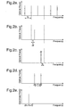
- Figure 2 diagrammatically illustrates a typical comb line that might be seen at the output of the OCG. The whole spectrum is presented to the inputs of the frequency selection and translation devices 3, 5.
- Figure 2b illustrates how the selection and translation device 3 selects a particular component of the OCG spectrum and translates it by f 1 .
- Figure 2c illustrates how the selection and translation device 5 selects a second component of the OCG spectrum and translates it by f 2 .
- the comb line selected by device 5 is separated from that which is selected by device 3 by 2 f c .
- Figure 2d shows that the optical spectrum presented to the optical detector as result of combing the output of frequency selection and translation devices 3 and 5 comprises two optical components separated by 2 f c - f 1 +f 2 .
- Figure 2e shows that the RF spectrum following envelop detection comprises a single component at 2 f c - f 1 +f 2 .
- Figure 3 shows in more detail the operation of one type of frequency selecting and translating device, the OPLL.
- the input from the OFC generator 1 is combined with a sample of the output from a tuneable slave laser 14, SL, such that their electric fields overlap, before detection in a photo-detector 16, PD.
- the output from the PD 16 is amplified in an amplifier 17, A and fed to the signal input of a mixer 18, M.
- the offset frequency , f n is applied to the local oscillator input of the mixer 18.
- the intermediate frequency output port of the mixer 18, which must have a frequency response extending to zero frequency, is connected to the input of a loop filter 19, LF.
- LF 19 is designed in accordance with well known phase-lock loop theory to have a passband substantially less than the minimum required offset frequency f n .
- LF 19 may incorporate lock acquisition and detection circuits.
- the output from LF 19 is connected to the tuning control of SL 14.
- SL 14 can be a tuneable external cavity laser or preferably a monolithic tuneable laser.
- the output from SL 14 forms the output from the frequency selecting and translating mechanism.
- OPLLs are suitable for use where the time taken for the signal to propagate around the control loop is small relative to the reciprocal of the spectral linewidth of SL 14.
- FIG. 4 shows in more detail the operation of another type of frequency selecting and translating device, the heterodyne OIPLL..
- a frequency translating device 20, T which could be an optical intensity or phase modulator or an optical single sideband modulator using electro-optic, acousto-optic or other physical principles, is added into the OPLL circuit described above. It is used to translate the OFC generator's spectrum by the required offset.
- the output from T 20 is coupled to the slave laser 14 so as to injection-lock it to the required offset output frequency.
- This approach avoids the control loop delay restrictions of the OPLL and is therefore well suited for applications where SL 14 is a monolithic semiconductor laser.
- phase lock loop path from PD through A, M and LF to SL can be designed with a narrow bandwidth to track the environmental disturbances on SL and so provide much wider locking ranges than could be obtained if only injection-locking were used.
- the path lengths between the offset source and T 20, and between the offset source and M are adjusted so that the injection locking and phase locking processes add constructively.
- Figure 5 shows in more detail the operation of another type of frequency selecting and translating device, the filtered acousto-optic or electro-optic translator.
- a frequency translating device which could be an optical intensity or phase modulator or an optical single sideband modulator using electro-optic, acousto-optic or other physical principles, is used to translate the comb spectrum by the required offset.
- the output from T feeds a tuneable optical filter, TF, which is tuned by a control input to select the required offset comb line. If non single sideband translating devices are used this approach requires that the minimum offset frequency be large relative to the bandwidth of the tuneable optical filter.
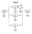
- Figure 6 shows an optical modulator 21 in the optical path from one of the optical frequency translation and selection devices, which allows the system to generate modulated signals.
- the modulation signal f m would be a baseband signal, but may be an Intermediate Frequency (IF) signal that itself comprises a carrier that has been modulated with a baseband signal.
- IF Intermediate Frequency
- Modulators could be positioned in the optical paths of a plurality of the selection and translation devices to increase the versatility of the final RF signal produced.
- the modulator is shown in Figure 6 as being positioned before the signals are combined, it could also be positioned after the combiner, but would then only be able to add the same modulation signal to all optical signals
- the outputs of the frequency selection and translation devices 3, 5 are combined and applied to the photodetector.
- the photodetector should have a bandwidth greater than the maximum frequency to be generated.
- the combination process should be arranged so that the electric fields of the two optical outputs overlap, as discussed above.
- Communications systems that incorporate the present invention will have particular benefits. Wide band communication are possible, and frequency changes can be made quickly. Also, signals having multiple outputs can be produced, each having an independent modulation signal. This may be particularly suitable for generating signals for multiple mobile receivers. The system will also have benefits if incorporated into radar systems, where it is often necessary to generate wideband modulated waveforms.
- the level of spurious outputs is determined by the filtering effectiveness of the optical frequency selecting or optical frequency selecting and translating devices. Using injection locked SG-DBR lasers with a comb line spacing of 17.5 GHz a suppression of adjacent comb lines of > 30 dB has been demonstrated 7 , corresponding to a suppression of > 60 dB in the detected RF output.
Landscapes
- Optical Communication System (AREA)
- Organic Low-Molecular-Weight Compounds And Preparation Thereof (AREA)
- Optical Modulation, Optical Deflection, Nonlinear Optics, Optical Demodulation, Optical Logic Elements (AREA)
- Stabilization Of Oscillater, Synchronisation, Frequency Synthesizers (AREA)
- Control Of Motors That Do Not Use Commutators (AREA)
- Lasers (AREA)
Claims (21)
- Frequenzgenerator mit einer ersten optischen Frequenzauswahl- und -verschiebungseinrichtung (3), die dazu verwendet wird, ein erstes optisches Ausgangssignal (8) bereitzustellen, und einem optischen Referenzoszillatorsystem (1); und
einer Detektoreinrichtung mit einem optischen Eingang und einem Hochfrequenzausgang;
dadurch gekennzeichnet, dass:das optische Referenzoszillatorsystein dazu eingerichtet ist, wenigstens ein optisches Referenzausgangssignal bei wenigstens einer ersten und einer zweiten Frequenz bereitzustellen, unddie optische Frequenzauswahl- und -verschiebungseinrichtung mit einem Ausgangssignal des optischen Referenzoszillatorsystems frequenzverrastet ist,und ein zweites optisches Ausgangssignal von einer zweiten optischen Frequenzauswahl- und -verschiebungseinrichtung (5) bereitgestellt wird, das mit einem Ausgangssignal des optischen Referenzoszillatorsystems verrastet ist,und wobei das erste und das zweite optische Ausgangssignal dazu eingerichtet ist, in optischer Kommunikation mit der Detektoreinrichtungen zu stehen. - Frequenzgenerator nach Anspruch 1, bei dem eine hochfrequenter Referenzfrequenz, die in jede Frequenzauswahl- und -verschiebungseinrichtung eingegeben wird, verwendet wird, um eine Frequenzdifferenz zwischen dem Eingangssignal aus dem optischen Referenzoszillatorsystem und dem Ausgangssignal aus der Frequenzauswahl- und -verschiebungseinrichtung abzuleiten.
- Frequenzgenerator nach Anspruch 2, bei dem die Referenzfrequenzen, mit denen jede Frequenzauswahl- und -verschiebungseinrichtung verrastet ist, verschieden sind.
- Frequenzgenerator nach Anspruch 3, bei dem das optische Referenzoszillatorsystem und alle Hochfrequenzreferenzen mit einem gemeinsamen Referenzsignal der Frequenz verbunden sind.
- Frequenzgenerator nach einem der Ansprüche 1 bis 4, bei dem wenigstens eine Frequenzauswahl- und -verschiebungseinrichtung ein heterodyner Phase-Locked-Loop ist.
- Frequenzgenerator nach einem der Ansprüche 1 bis 4, bei dem wenigstens eine Frequenzauswahl- und -verschiebungseinrichtung ein heterodyner optischer Phase-Locked-Loop mit Injektionsverrastung ist.
- Frequenzgenerator nach einem der Ansprüche 1 bis 4, bei dem wenigstens eine Frequenzauswahl- und -verschiebungseinrichtung ein akustooptischer Frequenzschieber ist.
- Frequenzgenerator nach einem der Ansprüche 1 bis 4, bei dem wenigstens eine Frequenzauswahl- und -verschiebungseinrichtung ein elektrooptischer Frequenzschieber ist.
- Frequenzgenerator nach einem der Ansprüche 1 bis 4, bei dem wenigstens eine Frequenzauswahl- und -verschiebungseinrichtung ein optischer Phase-Locked-Loop mit Injektionsverrastung ist.
- Frequenzgenerator nach einem der Ansprüche 1 bis 9, bei dem die Frequenzauswahl- und -verschiebungseinrichtung mit einem Modulationssignal im Basisband gespeist wird.
- Frequenzgenerator nach einem der Ansprüche 1 bis 10, bei dem das optische Ausgangssignal aus der Frequenzauswahl- und - verschiebungseinrichtung in einen optischen Modulator gespeist wird.
- Frequenzgenerator nach einem der vorangehenden Ansprüche, bei dem das optische Referenzoszillatorsystem ein optischer Frequenzkammgenerator ist.
- Frequenzgenerator nach Anspruch 1.2, bei dem der Frequenzabstand zwischen nebeneinanderliegenden Ausgangssignalen von der Frequenz eines Referenzsignals abhängt, das in den optischen Frequenzkammgenerator eingegeben wird.
- des Frequenzgenerator nach Anspruch 13, bei dem der optische Frequenzkammgenerator ein optisch-parametrischer Oszillator - Frequenzteiler (Optical Parametric Oscillator Frequency Divider) ist.
- Frequenzgenerator nach Anspruch 13, bei dem der optische Frequenzkammgenerator ein elektrooptischer optischer Frequenzkammgenerator mit externem Resonanzraum ist.
- Frequenzgenerator nach Anspruch 13, bei dem der optische Frequenzkammgenerator eine Faserringstruktur einsetzt.
- Frequenzgenerator nach Anspruch 13, bei dem der optische Frequenzkammgenerator einen modenverrasteten Laser einsetzt.
- Frequenzgenerator nach einem der Ansprüche 1 bis 17, bei dem die Detektoreinrichtung einen Fotodetektor umfasst
- Kommunikationssystem, das einen Frequenzgenerator nach einem der vorangehenden Ansprüche enthält.
- Radarsystem, das einen Frequenzgenerator nach einem der Ansprüche 1 bis 18 enthält.
- Verfahren zur Erzeugung eines Signals, das die folgenden Schritte umfasst:Bereitstellen eines Referenzsystems mit einem Ausgangssignal, das mehrere Spektrallinien innerhalb des Frequenzbandes aufweist, das von einem Laser verwendet wird;Anlegen dieses Ausgangssignals an eine erste Frequenzauswahl- und -verschiebungseinrichtung (3), die ein Ausgangssignal aufweist, das eine einzelne Spektrallinie umfasst, die aus denen an ihrem Eingang ausgewählt ist, die im Frequenzbereich um einen Betrag verschoben ist, der durch ein Eingangssignal mit Referenzfrequenz festgelegt wird;Anlegen dieses Ausgangssignals an eine zweite Frequenzauswahl- und -verschiebungseinrichtung (5), die ein Ausgangssignal aufweist, das eine einzelne Spektrallinie umfasst, die aus denen an ihrem Eingang ausgewählt ist, die im Frequenzbereich um einen Betrag verschoben ist, der durch ein Eingangssignal mit Referenzfrequenz festgelegt wird;Aufnehmen der Ausgangssignale aus der ersten und der zweiten Frequenzauswahl- und -verschiebungseinrichtung und Überlagern und Abwärtswandlung der zwei Ausgangssignale, um ein Hochfrequenzsignal (8) zu erzeugen.
Applications Claiming Priority (3)
| Application Number | Priority Date | Filing Date | Title |
|---|---|---|---|
| GB0025662 | 2000-10-19 | ||
| GBGB0025662.8A GB0025662D0 (en) | 2000-10-19 | 2000-10-19 | Frequency synthesiser |
| PCT/GB2001/004570 WO2002033818A2 (en) | 2000-10-19 | 2001-10-15 | Frequency synthesiser |
Publications (2)
| Publication Number | Publication Date |
|---|---|
| EP1327298A2 EP1327298A2 (de) | 2003-07-16 |
| EP1327298B1 true EP1327298B1 (de) | 2006-12-27 |
Family
ID=9901628
Family Applications (1)
| Application Number | Title | Priority Date | Filing Date |
|---|---|---|---|
| EP01978578A Expired - Lifetime EP1327298B1 (de) | 2000-10-19 | 2001-10-15 | Frequenzsynthesizer |
Country Status (9)
| Country | Link |
|---|---|
| US (1) | US6980353B2 (de) |
| EP (1) | EP1327298B1 (de) |
| JP (1) | JP4072053B2 (de) |
| AT (1) | ATE349723T1 (de) |
| AU (1) | AU2002210678A1 (de) |
| CA (1) | CA2426116A1 (de) |
| DE (1) | DE60125566T2 (de) |
| GB (1) | GB0025662D0 (de) |
| WO (1) | WO2002033818A2 (de) |
Families Citing this family (14)
| Publication number | Priority date | Publication date | Assignee | Title |
|---|---|---|---|---|
| AU2003221717A1 (en) * | 2002-04-17 | 2003-11-03 | Hrl Laboratories, Llc | Method and apparatus for producing an optical output |
| US7603037B2 (en) * | 2003-06-20 | 2009-10-13 | Hrl Laboratories, Llc | Ultra-dense wavelength and subcarrier multiplexed optical and RF/mm-wave transmission system |
| GB0417394D0 (en) * | 2004-08-04 | 2004-09-08 | Council Cent Lab Res Councils | Scanning imaging device |
| EP2040117A4 (de) * | 2006-07-11 | 2009-09-30 | Japan Science & Tech Agency | Vorrichtung und verfahren zur erzeugung von synchronisierten optischen signalen |
| KR100841052B1 (ko) * | 2006-10-11 | 2008-06-24 | 한국표준과학연구원 | 펨토초레이저 광주입잠금을 이용한 주사 광주파수합성기 및상기 광주파수합성기를 이용한 광주파수합성방법 |
| US8811439B2 (en) | 2009-11-23 | 2014-08-19 | Seminex Corporation | Semiconductor laser assembly and packaging system |
| US8848752B2 (en) | 2011-01-18 | 2014-09-30 | Phase Sensitive Innovations, Inc. | High spectral-purity carrier wave generation by nonlinear optical mixing |
| CN103944561B (zh) * | 2014-04-09 | 2017-03-15 | 上海交通大学 | 基于声光移频器的光锁相环实现系统及实现方法 |
| JP2017111276A (ja) | 2015-12-16 | 2017-06-22 | 大学共同利用機関法人自然科学研究機構 | 光シンセサイザ |
| WO2018149508A1 (en) | 2017-02-20 | 2018-08-23 | Luz Wavelabs, S.L. | Automatic and programmable signal generation method in the radiofrequency, milimeter wave and terahertz frequency regions with low phase noise, wide frequency tuning range, high modulation bandwidth and high frequency resolution |
| CN111048978B (zh) | 2018-10-12 | 2021-04-20 | 华为技术有限公司 | 一种多波长激光器 |
| JP6994128B1 (ja) | 2021-03-29 | 2022-02-03 | 株式会社Xtia | 光コム発生装置 |
| US20240429925A1 (en) * | 2023-06-20 | 2024-12-26 | University Of Georgia Research Foundation, Inc. | Electro-optic Frequency Comb Generation with Harmonic RF Modulation |
| CN117240308B (zh) * | 2023-08-07 | 2026-04-14 | 中国电子科技集团公司第二十九研究所 | 一种基于光频梳的高性能微波频率合成及控制方法 |
Family Cites Families (7)
| Publication number | Priority date | Publication date | Assignee | Title |
|---|---|---|---|---|
| US4893353A (en) | 1985-12-20 | 1990-01-09 | Yokogawa Electric Corporation | Optical frequency synthesizer/sweeper |
| US5335106A (en) * | 1992-10-30 | 1994-08-02 | Mpb Technologies Inc. | Optically-based frequency synthesizer for generating an electric output signal at a preselected frequency that can be changed over a wide band of frequencies for communication purpose |
| JP3033650B2 (ja) * | 1993-06-30 | 2000-04-17 | 安藤電気株式会社 | 光周波数シンセサイザ |
| US5379309A (en) * | 1993-08-16 | 1995-01-03 | California Institute Of Technology | High frequency source having heterodyned laser oscillators injection-locked to a mode-locked laser |
| US5777778A (en) * | 1996-01-23 | 1998-07-07 | California Institute Of Technology | Multi-Loop opto-electronic microwave oscillator with a wide tuning range |
| US6560452B1 (en) * | 2000-11-27 | 2003-05-06 | Rf Micro Devices, Inc. | Oscillator having a transistor formed of a wide bandgap semiconductor material |
| JP4567231B2 (ja) * | 2001-04-12 | 2010-10-20 | 株式会社日立製作所 | 波長変換器および波長多重光通信装置 |
-
2000
- 2000-10-19 GB GBGB0025662.8A patent/GB0025662D0/en not_active Ceased
-
2001
- 2001-10-15 JP JP2002536705A patent/JP4072053B2/ja not_active Expired - Fee Related
- 2001-10-15 US US10/399,654 patent/US6980353B2/en not_active Expired - Fee Related
- 2001-10-15 AU AU2002210678A patent/AU2002210678A1/en not_active Abandoned
- 2001-10-15 AT AT01978578T patent/ATE349723T1/de not_active IP Right Cessation
- 2001-10-15 DE DE60125566T patent/DE60125566T2/de not_active Expired - Lifetime
- 2001-10-15 WO PCT/GB2001/004570 patent/WO2002033818A2/en not_active Ceased
- 2001-10-15 CA CA002426116A patent/CA2426116A1/en not_active Abandoned
- 2001-10-15 EP EP01978578A patent/EP1327298B1/de not_active Expired - Lifetime
Also Published As
| Publication number | Publication date |
|---|---|
| WO2002033818A2 (en) | 2002-04-25 |
| JP4072053B2 (ja) | 2008-04-02 |
| US6980353B2 (en) | 2005-12-27 |
| EP1327298A2 (de) | 2003-07-16 |
| US20040051936A1 (en) | 2004-03-18 |
| JP2004512556A (ja) | 2004-04-22 |
| ATE349723T1 (de) | 2007-01-15 |
| DE60125566D1 (de) | 2007-02-08 |
| CA2426116A1 (en) | 2002-04-25 |
| AU2002210678A1 (en) | 2002-04-29 |
| DE60125566T2 (de) | 2007-05-03 |
| GB0025662D0 (en) | 2000-12-06 |
| WO2002033818A3 (en) | 2003-01-30 |
Similar Documents
| Publication | Publication Date | Title |
|---|---|---|
| US6963442B2 (en) | Low-noise, switchable RF-lightwave synthesizer | |
| US6980353B2 (en) | Frequency synthesiser | |
| CN108768539B (zh) | 光子型微波二分频方法及光子型微波二分频器 | |
| CN109842450B (zh) | 光子型可切换微波分频方法及装置 | |
| Balakier et al. | Optical phase lock loop as high-quality tuneable filter for optical frequency comb line selection | |
| Sturzebecher et al. | Optically controlled oscillators for millimeter-wave phased-array antennas | |
| Zhang et al. | Passively stabilized Brillouin fiber laser frequency combs for ultralow-noise microwave generation | |
| CN111916982B (zh) | 光本振生成系统及方法 | |
| US5302918A (en) | Subharmonic optically injection locked oscillator | |
| Chen et al. | Microwave frequency division based on optically injected DFB-LD with an OEO loop | |
| Yao | Microwave photonics: Photonic generation of microwave and millimeter-wave signals | |
| Peng et al. | Low phase noise 20 GHz microwave frequency divider based on a super-harmonic injection locked optoelectronic oscillator | |
| US5335106A (en) | Optically-based frequency synthesizer for generating an electric output signal at a preselected frequency that can be changed over a wide band of frequencies for communication purpose | |
| Lin et al. | Broad-band (/spl ges/20 GHz) laser-diode-based optoelectronic microwave phase shifter | |
| Sun et al. | Frequency synthesis of forced opto-electronic oscillators at the X-band | |
| Eliyahu et al. | Ultra-wideband photonic VCO and synthesizer | |
| JP2003195380A (ja) | 光学的ミリ波あるいはサブミリ波の発生装置 | |
| JP3974255B2 (ja) | 周波数可変レーザ光源装置 | |
| Lunavath et al. | Photonics based ESM receiver for EW applications | |
| WO2003090385A2 (en) | Method and apparatus for frequency synthesis | |
| Yuan et al. | Phase-locked Tri-band Broadband Signal Generation from Injection-locked Fourier Domain Mode-locked Optoelectronic Oscillator | |
| Landecker et al. | A phase-stabilized local-oscillator system for a synthesis radio telescope | |
| Bester | Phaselock system for millimeter-wave Gunn oscillators used in radio astronomy and laboratory spectroscopy | |
| Tang et al. | Microwave Frequency Divider With Tunable Division Factors Based on an Optoelectronic Oscillator | |
| Kuo et al. | A Ka-band YIG-based local oscillator for astronomical heterodyne receiver |
Legal Events
| Date | Code | Title | Description |
|---|---|---|---|
| PUAI | Public reference made under article 153(3) epc to a published international application that has entered the european phase |
Free format text: ORIGINAL CODE: 0009012 |
|
| 17P | Request for examination filed |
Effective date: 20030513 |
|
| AK | Designated contracting states |
Designated state(s): AT BE CH CY DE DK ES FI FR GB GR IE IT LI LU MC NL PT SE TR |
|
| AX | Request for extension of the european patent |
Extension state: AL LT LV MK RO SI |
|
| 17Q | First examination report despatched |
Effective date: 20040216 |
|
| GRAP | Despatch of communication of intention to grant a patent |
Free format text: ORIGINAL CODE: EPIDOSNIGR1 |
|
| RIC1 | Information provided on ipc code assigned before grant |
Ipc: G02F 1/35 20060101AFI20060615BHEP |
|
| RIC1 | Information provided on ipc code assigned before grant |
Ipc: H03D 7/00 20060101ALI20060704BHEP Ipc: G02F 1/35 20060101AFI20060704BHEP |
|
| GRAS | Grant fee paid |
Free format text: ORIGINAL CODE: EPIDOSNIGR3 |
|
| GRAA | (expected) grant |
Free format text: ORIGINAL CODE: 0009210 |
|
| AK | Designated contracting states |
Kind code of ref document: B1 Designated state(s): AT BE CH CY DE DK ES FI FR GB GR IE IT LI LU MC NL PT SE TR |
|
| PG25 | Lapsed in a contracting state [announced via postgrant information from national office to epo] |
Ref country code: FI Free format text: LAPSE BECAUSE OF FAILURE TO SUBMIT A TRANSLATION OF THE DESCRIPTION OR TO PAY THE FEE WITHIN THE PRESCRIBED TIME-LIMIT Effective date: 20061227 Ref country code: IT Free format text: LAPSE BECAUSE OF FAILURE TO SUBMIT A TRANSLATION OF THE DESCRIPTION OR TO PAY THE FEE WITHIN THE PRESCRIBED TIME-LIMIT;WARNING: LAPSES OF ITALIAN PATENTS WITH EFFECTIVE DATE BEFORE 2007 MAY HAVE OCCURRED AT ANY TIME BEFORE 2007. THE CORRECT EFFECTIVE DATE MAY BE DIFFERENT FROM THE ONE RECORDED. Effective date: 20061227 Ref country code: DK Free format text: LAPSE BECAUSE OF FAILURE TO SUBMIT A TRANSLATION OF THE DESCRIPTION OR TO PAY THE FEE WITHIN THE PRESCRIBED TIME-LIMIT Effective date: 20061227 Ref country code: NL Free format text: LAPSE BECAUSE OF FAILURE TO SUBMIT A TRANSLATION OF THE DESCRIPTION OR TO PAY THE FEE WITHIN THE PRESCRIBED TIME-LIMIT Effective date: 20061227 Ref country code: LI Free format text: LAPSE BECAUSE OF FAILURE TO SUBMIT A TRANSLATION OF THE DESCRIPTION OR TO PAY THE FEE WITHIN THE PRESCRIBED TIME-LIMIT Effective date: 20061227 Ref country code: BE Free format text: LAPSE BECAUSE OF FAILURE TO SUBMIT A TRANSLATION OF THE DESCRIPTION OR TO PAY THE FEE WITHIN THE PRESCRIBED TIME-LIMIT Effective date: 20061227 Ref country code: AT Free format text: LAPSE BECAUSE OF FAILURE TO SUBMIT A TRANSLATION OF THE DESCRIPTION OR TO PAY THE FEE WITHIN THE PRESCRIBED TIME-LIMIT Effective date: 20061227 Ref country code: CH Free format text: LAPSE BECAUSE OF FAILURE TO SUBMIT A TRANSLATION OF THE DESCRIPTION OR TO PAY THE FEE WITHIN THE PRESCRIBED TIME-LIMIT Effective date: 20061227 |
|
| REG | Reference to a national code |
Ref country code: GB Ref legal event code: FG4D |
|
| REG | Reference to a national code |
Ref country code: IE Ref legal event code: FG4D |
|
| REF | Corresponds to: |
Ref document number: 60125566 Country of ref document: DE Date of ref document: 20070208 Kind code of ref document: P |
|
| PG25 | Lapsed in a contracting state [announced via postgrant information from national office to epo] |
Ref country code: SE Free format text: LAPSE BECAUSE OF FAILURE TO SUBMIT A TRANSLATION OF THE DESCRIPTION OR TO PAY THE FEE WITHIN THE PRESCRIBED TIME-LIMIT Effective date: 20070327 |
|
| PG25 | Lapsed in a contracting state [announced via postgrant information from national office to epo] |
Ref country code: ES Free format text: LAPSE BECAUSE OF FAILURE TO SUBMIT A TRANSLATION OF THE DESCRIPTION OR TO PAY THE FEE WITHIN THE PRESCRIBED TIME-LIMIT Effective date: 20070407 |
|
| PG25 | Lapsed in a contracting state [announced via postgrant information from national office to epo] |
Ref country code: PT Free format text: LAPSE BECAUSE OF FAILURE TO SUBMIT A TRANSLATION OF THE DESCRIPTION OR TO PAY THE FEE WITHIN THE PRESCRIBED TIME-LIMIT Effective date: 20070528 |
|
| NLV1 | Nl: lapsed or annulled due to failure to fulfill the requirements of art. 29p and 29m of the patents act | ||
| ET | Fr: translation filed | ||
| REG | Reference to a national code |
Ref country code: CH Ref legal event code: PL |
|
| REG | Reference to a national code |
Ref country code: GB Ref legal event code: 732E |
|
| PLBE | No opposition filed within time limit |
Free format text: ORIGINAL CODE: 0009261 |
|
| STAA | Information on the status of an ep patent application or granted ep patent |
Free format text: STATUS: NO OPPOSITION FILED WITHIN TIME LIMIT |
|
| 26N | No opposition filed |
Effective date: 20070928 |
|
| PG25 | Lapsed in a contracting state [announced via postgrant information from national office to epo] |
Ref country code: GR Free format text: LAPSE BECAUSE OF FAILURE TO SUBMIT A TRANSLATION OF THE DESCRIPTION OR TO PAY THE FEE WITHIN THE PRESCRIBED TIME-LIMIT Effective date: 20070328 |
|
| PG25 | Lapsed in a contracting state [announced via postgrant information from national office to epo] |
Ref country code: MC Free format text: LAPSE BECAUSE OF NON-PAYMENT OF DUE FEES Effective date: 20071031 |
|
| PG25 | Lapsed in a contracting state [announced via postgrant information from national office to epo] |
Ref country code: IE Free format text: LAPSE BECAUSE OF NON-PAYMENT OF DUE FEES Effective date: 20071015 |
|
| PG25 | Lapsed in a contracting state [announced via postgrant information from national office to epo] |
Ref country code: CY Free format text: LAPSE BECAUSE OF FAILURE TO SUBMIT A TRANSLATION OF THE DESCRIPTION OR TO PAY THE FEE WITHIN THE PRESCRIBED TIME-LIMIT Effective date: 20061227 Ref country code: LU Free format text: LAPSE BECAUSE OF NON-PAYMENT OF DUE FEES Effective date: 20071015 |
|
| PG25 | Lapsed in a contracting state [announced via postgrant information from national office to epo] |
Ref country code: TR Free format text: LAPSE BECAUSE OF FAILURE TO SUBMIT A TRANSLATION OF THE DESCRIPTION OR TO PAY THE FEE WITHIN THE PRESCRIBED TIME-LIMIT Effective date: 20061227 |
|
| PGFP | Annual fee paid to national office [announced via postgrant information from national office to epo] |
Ref country code: GB Payment date: 20120925 Year of fee payment: 12 |
|
| PGFP | Annual fee paid to national office [announced via postgrant information from national office to epo] |
Ref country code: DE Payment date: 20121031 Year of fee payment: 12 Ref country code: FR Payment date: 20121010 Year of fee payment: 12 |
|
| GBPC | Gb: european patent ceased through non-payment of renewal fee |
Effective date: 20131015 |
|
| PG25 | Lapsed in a contracting state [announced via postgrant information from national office to epo] |
Ref country code: GB Free format text: LAPSE BECAUSE OF NON-PAYMENT OF DUE FEES Effective date: 20131015 |
|
| REG | Reference to a national code |
Ref country code: FR Ref legal event code: ST Effective date: 20140630 |
|
| REG | Reference to a national code |
Ref country code: DE Ref legal event code: R119 Ref document number: 60125566 Country of ref document: DE Effective date: 20140501 |
|
| PG25 | Lapsed in a contracting state [announced via postgrant information from national office to epo] |
Ref country code: DE Free format text: LAPSE BECAUSE OF NON-PAYMENT OF DUE FEES Effective date: 20140501 Ref country code: FR Free format text: LAPSE BECAUSE OF NON-PAYMENT OF DUE FEES Effective date: 20131031 |