EP1327480A1 - Flüssigkeitssprühvorrichtung - Google Patents
Flüssigkeitssprühvorrichtung Download PDFInfo
- Publication number
- EP1327480A1 EP1327480A1 EP01972644A EP01972644A EP1327480A1 EP 1327480 A1 EP1327480 A1 EP 1327480A1 EP 01972644 A EP01972644 A EP 01972644A EP 01972644 A EP01972644 A EP 01972644A EP 1327480 A1 EP1327480 A1 EP 1327480A1
- Authority
- EP
- European Patent Office
- Prior art keywords
- liquid
- section
- distal end
- mesh
- mesh member
- Prior art date
- Legal status (The legal status is an assumption and is not a legal conclusion. Google has not performed a legal analysis and makes no representation as to the accuracy of the status listed.)
- Granted
Links
Images






Classifications
-
- B—PERFORMING OPERATIONS; TRANSPORTING
- B05—SPRAYING OR ATOMISING IN GENERAL; APPLYING FLUENT MATERIALS TO SURFACES, IN GENERAL
- B05B—SPRAYING APPARATUS; ATOMISING APPARATUS; NOZZLES
- B05B17/00—Apparatus for spraying or atomising liquids or other fluent materials, not covered by the preceding groups
- B05B17/04—Apparatus for spraying or atomising liquids or other fluent materials, not covered by the preceding groups operating with special methods
- B05B17/06—Apparatus for spraying or atomising liquids or other fluent materials, not covered by the preceding groups operating with special methods using ultrasonic or other kinds of vibrations
-
- B—PERFORMING OPERATIONS; TRANSPORTING
- B05—SPRAYING OR ATOMISING IN GENERAL; APPLYING FLUENT MATERIALS TO SURFACES, IN GENERAL
- B05B—SPRAYING APPARATUS; ATOMISING APPARATUS; NOZZLES
- B05B17/00—Apparatus for spraying or atomising liquids or other fluent materials, not covered by the preceding groups
- B05B17/04—Apparatus for spraying or atomising liquids or other fluent materials, not covered by the preceding groups operating with special methods
- B05B17/06—Apparatus for spraying or atomising liquids or other fluent materials, not covered by the preceding groups operating with special methods using ultrasonic or other kinds of vibrations
- B05B17/0607—Apparatus for spraying or atomising liquids or other fluent materials, not covered by the preceding groups operating with special methods using ultrasonic or other kinds of vibrations generated by electrical means, e.g. piezoelectric transducers
- B05B17/0638—Apparatus for spraying or atomising liquids or other fluent materials, not covered by the preceding groups operating with special methods using ultrasonic or other kinds of vibrations generated by electrical means, e.g. piezoelectric transducers spray being produced by discharging the liquid or other fluent material through a plate comprising a plurality of orifices
-
- B—PERFORMING OPERATIONS; TRANSPORTING
- B05—SPRAYING OR ATOMISING IN GENERAL; APPLYING FLUENT MATERIALS TO SURFACES, IN GENERAL
- B05B—SPRAYING APPARATUS; ATOMISING APPARATUS; NOZZLES
- B05B17/00—Apparatus for spraying or atomising liquids or other fluent materials, not covered by the preceding groups
- B05B17/04—Apparatus for spraying or atomising liquids or other fluent materials, not covered by the preceding groups operating with special methods
- B05B17/06—Apparatus for spraying or atomising liquids or other fluent materials, not covered by the preceding groups operating with special methods using ultrasonic or other kinds of vibrations
- B05B17/0607—Apparatus for spraying or atomising liquids or other fluent materials, not covered by the preceding groups operating with special methods using ultrasonic or other kinds of vibrations generated by electrical means, e.g. piezoelectric transducers
- B05B17/0623—Apparatus for spraying or atomising liquids or other fluent materials, not covered by the preceding groups operating with special methods using ultrasonic or other kinds of vibrations generated by electrical means, e.g. piezoelectric transducers coupled with a vibrating horn
-
- B—PERFORMING OPERATIONS; TRANSPORTING
- B05—SPRAYING OR ATOMISING IN GENERAL; APPLYING FLUENT MATERIALS TO SURFACES, IN GENERAL
- B05B—SPRAYING APPARATUS; ATOMISING APPARATUS; NOZZLES
- B05B17/00—Apparatus for spraying or atomising liquids or other fluent materials, not covered by the preceding groups
- B05B17/04—Apparatus for spraying or atomising liquids or other fluent materials, not covered by the preceding groups operating with special methods
- B05B17/06—Apparatus for spraying or atomising liquids or other fluent materials, not covered by the preceding groups operating with special methods using ultrasonic or other kinds of vibrations
- B05B17/0607—Apparatus for spraying or atomising liquids or other fluent materials, not covered by the preceding groups operating with special methods using ultrasonic or other kinds of vibrations generated by electrical means, e.g. piezoelectric transducers
- B05B17/0623—Apparatus for spraying or atomising liquids or other fluent materials, not covered by the preceding groups operating with special methods using ultrasonic or other kinds of vibrations generated by electrical means, e.g. piezoelectric transducers coupled with a vibrating horn
- B05B17/063—Apparatus for spraying or atomising liquids or other fluent materials, not covered by the preceding groups operating with special methods using ultrasonic or other kinds of vibrations generated by electrical means, e.g. piezoelectric transducers coupled with a vibrating horn having an internal channel for supplying the liquid or other fluent material
Definitions
- the present invention relates to a liquid atomizing apparatus, and more particularly to an ultrasonic mesh type liquid atomizing apparatus atomizing a liquid using a horn oscillating member and a mesh member.
- a conventional ultrasonic type liquid atomizing apparatus has a liquid atomizing construction as an example, as shown in Fig. 17.
- a liquid atomizing construction shown herein includes: a liquid reservoir section (a bottle) 70 reserving a liquid (a chemical liquid) L; an ultrasonic pump (a horn oscillating member) 77; and a mesh member 80.
- Horn oscillating member 77 is constructed of: a pipe 74 having liquid-suction through holes (water suction holes) 73 extending along an axial direction, and communicating from a lower end 71 located in bottle 70 to an opening provided at the top end 72 located outside bottle 70; and two annular oscillating members 75 and 76 mounted to pipe 74.
- Mesh member 80 is mounted to pipe top end 72 in contact therewith using an elastic member (not shown) such as a coil spring.
- a high frequency voltage generated by an oscillator 78 is applied to annular oscillating members 75 and 76, thereby causing annular oscillating members 75 and 76 to be ultrasonically oscillated and to oscillate pipe 74 upward and downward.
- chemical liquid L in bottle 70 is sucked up from lower end 71 of pipe 74 through water suction holes 73 to come out of the opening of top end 72.
- Chemical liquid L is atomized away in a state of a fog by means of the mesh member 80 mounted to top end 72 in contact therewith.
- a liquid atomizing construction different from the above construction has been contrived in which pressure means such as a piston pressurizing a chemical liquid in a bottle is provided instead of a pipe having the above water suction holes, whereby the chemical liquid reserved in the bottle is little by little fed to an atomizing section (a contact section between the top end of the horn oscillating member and the mesh member).
- pressure means such as a piston pressurizing a chemical liquid in a bottle is provided instead of a pipe having the above water suction holes, whereby the chemical liquid reserved in the bottle is little by little fed to an atomizing section (a contact section between the top end of the horn oscillating member and the mesh member).
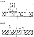
- fine pores 81 and 82 of mesh members 80A and 80B as shown in Figs. 18 and 19, have a step profile and a tapered profile, respectively, each so as to be formed narrower toward the discharge side of liquid droplets 83 and wider in the surface side (the lower side in the view from above in the figure) thereof in contact with horn oscillating member 77 in longitudinal section.
- Mesh members 80A and 80B are important factors in determination of an atomizing performance of a liquid atomizing apparatus, but acting as a main cause for clogging and degradation in performance of the mesh.
- For the purpose of raising a density of fine pores 81 or 82 is useful in order to enhance an atomizing efficiency, but with a distance between fine pores 81 or 82 made shorter with the result that degradation in strength of a mesh member occurs and droplets 83 jetted to outside, as shown in Fig. 18, lose directivity thereof to aggregate into dew drops 84 of large diameters.
- a first object of the present invention to simplify a feed structure for a liquid from a liquid reservoir section to an atomizing section, and it is a second object of the present invention to provide a liquid atomizing apparatus realizing no leakage of a liquid regardless of a degree of inclination thereof.
- a liquid atomizing apparatus of the present invention includes: a liquid reservoir section reserving a liquid; an oscillation source to whose distal end the liquid in the liquid reservoir section is fed; and a mesh member having many fine pores, and mounted to an end surface of the distal end of the oscillation source in contact therewith, the liquid in the liquid reservoir section being atomized by an oscillation action of combination of the oscillation source and the mesh member, wherein the liquid reservoir section is formed such that when the apparatus is inclined to the oscillation source side, the liquid therein reaches as far as a point in the proximity of a contact section between the distal end of the oscillation source and the mesh member, while when the apparatus is held in a horizontal state, the liquid does not reach as far as a point in the proximity of the contact section.
- the liquid in the liquid reservoir section is fed directly to a point in the proximity of the contact section (hereinafter also referred to as an atomizing section) between the distal end of the oscillation source and the mesh member, no necessity arises for a special liquid feed means and the apparatus can be obtained at a low cost with not only increased reliability but enhanced durability.
- the liquid fed to a point in the proximity of the atomizing section reaches the mesh member by an oscillation action of combination of the oscillation source and the mesh member and is atomized there.
- the liquid reservoir section is constituted of a large capacity section and a small capacity section in communication with the large capacity section, and opposing to the distal end of the oscillation source.
- the small capacity section is formed such that the liquid therein is in contact with a point in the proximity of the atomizing section.
- the liquid in the reservoir section first flows into the small capacity section from the large capacity section, and the liquid in the small capacity section is fed little by little to a point in the proximity of the atomizing section, and further reaches the mesh member and is atomized there by an oscillation action of combination of the oscillation source and the mesh member.
- the liquid reservoir section is formed such that, when the apparatus is held in a horizontal state (a case other than an ordinary atomization), if the liquid in the large capacity section is at a prescribed quantity or less, the liquid in the large capacity section and the liquid in the small capacity section are isolated from each other. With such a construction, even in a case where turning-off of a power supply switch is forgotten, the liquid remaining in the proximity of the atomization section is rendered to a very small quantity only, so none of the liquid is wasted.
- Both support members holding the mesh member therebetween are mounted on a mesh cap with packing and the mesh cap is further mounted to an opening section with another packing therebetween, resulting in no leakage of the liquid in the liquid reservoir section to outside through the opening section and improved easiness in handling.
- liquid leakage is easy to occur in a case of a construction as described above in which a chemical liquid is fed to an atomizing section from a liquid reservoir section by inclining a liquid atomizing apparatus during its use, such a liquid leakage is effectively prevented from occurring by adopting a liquid-tight structure as is in the above construction.
- a liquid atomizing apparatus of the present invention including: a liquid reservoir section reserving a liquid; an oscillation source to whose distal end the liquid in the liquid reservoir section is fed; and a mesh member having many fine pores, and mounted to an end surface of the distal end of oscillation source in contact therewith, the liquid in the liquid reservoir being atomized by an oscillation action of combination of the oscillation source and the mesh member, further including: an opening section through which an atomized chemical liquid is jetted; and a mesh cap mounted to the opening section, characterized in that the mesh member is held by one support member and the other support member therebetween and fixed to an end surface of the distal end of the oscillation source in contact therewith, both support members are mounted to the mesh cap with packing in one body and the mesh cap is mounted to the opening section with another packing therebetween.
- both support members holding the mesh member therebetween are mounted to the mesh cap with packing and the mesh cap is further mounted to the opening section with another packing therebetween, none of the liquid in the reservoir section is leaked to outside, thereby improving easiness in handling.
- both packing may be formed in one body therebetween or alternatively, each may be formed in one body with a corresponding partner: the support member, the mesh cap or the liquid reservoir section. In any case, the number of parts decreases, leading to easiness in assembly.
- a liquid atomizing apparatus of the present invention including: a liquid reservoir section reserving a liquid; an oscillation source to whose distal end the liquid in the liquid reservoir section is fed; and a mesh member having many fine pores, and mounted to an end surface of the distal end of the oscillation source in contact therewith, the liquid in the liquid reservoir section being atomized by an oscillation action of combination of the oscillation source and the mesh member, is characterized in that each of the fine pores of the mesh member includes: a liquid reserving portion formed in the side adjacent to the end surface of the distal end of the oscillation source; a hole through which the liquid in the liquid reserving portion is discharged as fine droplets; and a guide wall guiding the fine droplets discharged from the hole in the discharge direction.
- each of the fine pores of the mesh member includes: the liquid reserving portion, the hole, and the guide wall.
- the liquid from the liquid reservoir section flows into a gap between the oscillation source and the mesh member, and further enters the liquid reserving portions of the mesh member, and the liquid in the liquid reserving portions is discharged through the holes as fine droplets by the oscillation action of combination of the oscillation source and the mesh member.
- the discharged fine droplets are ushered in the discharge direction by the guide wall and is jetted.
- the fine droplets are ushered in the discharge direction by the guide wall with good directivity, droplets discharged through adjacent holes are hard to aggregate therebetween and to attach onto the atomization surface.
- recoupling of droplets therebetween is suppressed, a density of fine pores can be increased.
- a liquid reserving portion in a fine pore of the mesh member is designed to be circular in a cross section and not only is a depth of the liquid reserving portion thereof set to be equal to or more than an amplitude of the oscillation source, but a diameter of an inlet side thereof is also set to 10 times or less as large as that of a circular hole, stable atomization can be realized with more of efficiency.
- a depth of the liquid reserving portion circular in a cross section is set 10 ⁇ m or more, while if a diameter of the circular hole is 3 ⁇ m, a diameter of the inlet side of the liquid reserving portion is set to 30 ⁇ m or less.
- the mesh member is formed using a NiPd alloy by electroforming, a density of the fine pores can be further raised while keeping a sufficient strength with improvement on anticorrosiveness.
- the liquid atomizing apparatus includes: not only a power supply switch 21 but also a body section 20 having a built-in battery and electrical circuitry therein and a bottle unit 30 attached to the body section 20 in a demountable manner.
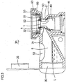
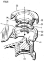
- Bottle unit 30 has a construction as shown in Figs. 2 (perspective view), Fig. 3 (longitudinal sectional view), Fig. 4 (partially cut-away perspective view of a main part), Fig. 5 (partially cut-away perspective view of a main part in an expanded configuration) and Fig. 6 (enlarged longitudinal sectional view of a main part).
- Bottle unit 30 is provided with: a liquid reservoir section (bottle section) 31 reserving a liquid (a chemical liquid) L ; an oscillation source (a horn oscillating member) 40 to the distal end of which chemical liquid L in bottle section 31 is fed; and a mesh member 1 having many fine pores and mounted to the end surface of distal end 41 of horn oscillating member 40 in contact therewith.
- Bottle section 31 as is apparent in Fig. 3, has an inclined bottom and the distal end opening 32 of its tapered body thereof, opposing to distal end 41 of horn oscillating member 40.
- Two caps 35 and 36 integrated in one body are mounted to bottle section 31 in a demountable manner.
- Cap 35 is for use in opening and closing liquid filling port 33 formed on bottle section 31, and cap 36 is for use in opening and closing an opening for use in cleaning (not attached with a symbol) formed on the other side of the tapered body from distal end opening 32. If caps 35 and 36 are both disengaged, cleaning inside bottle section 31 can be easily performed.
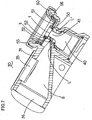
- Bottle section 31 is formed such that liquid L reaches to a point in the proximity of a contact section (an atomizing section) between the end surface of distal end 41 of horn oscillating member 40 and mesh member 1 in an ordinary atomization state (in an inclined state shown in Fig. 7) where the apparatus is inclined to horn oscillating member 40 side, while when the apparatus is held in a horizontal state (a horizontal state shown in Fig. 3), liquid L does not reach a point in the proximity of the atomizing section.
- bottle section 31 is constituted of a large capacity section B and a small capacity section b in communication with large capacity section B through opening 32, and opposing to distal end 41 of horn oscillating member 40.
- Small capacity section b is formed such that liquid L' reserved therein contacts a point in the proximity of the atomizing section. That is, small capacity section b is designed so as to have a capacity such that chemical liquid L' easily reach the atomizing section even with chemical liquid L' of a small quantity therein.
- small capacity section b is an annular space formed between an inner wall 62 of an opening section (a mesh cap mounting section) 60 through which atomized chemical liquid is jetted and distal end 41 of horn oscillating member 40. Therefore, chemical liquid L' flowing from large capacity section B of bottle section 31 to small capacity section b is eventually attached to the periphery of distal end 41.
- a spacing between inner wall 62 and distal end 41 of horn oscillating member 40 is set such that chemical liquid L' in small capacity section b in a state of a very small quantity of chemical liquid L' therein just prior to the time when chemical liquid L in large capacity section B is reduced to nothing, is fed as far as a point in the proximity of the atomizing section by a surface tension with mesh member 1 and distal end 41.
- Bottle section 31 is formed such that in a case where in a position thereof (a horizontal state shown in Fig. 3) other than an ordinary atomization state (an inclined state of Fig. 7), when chemical liquid L in large capacity section B is reduced to a prescribed quantity or less, chemical liquid L in large capacity section B and chemical liquid L' in small capacity section b are isolated from each other.
- a horn oscillating member 40 opposing opening 32 of bottle section 31 is mounted on the lower side of opening section 60 of bottle unit 30 and mesh cap 55 is mounted to opening section 60 at the top side of horn oscillating member 40 in a demountable manner.
- Mesh member 1 on distal end 41 of horn oscillating member 40 is held between one support member 50 and the other support member 52 and fixed to the end surface of distal end 41 in a contact state therewith. Both support members 50 and 52 in engagement are mounted to mesh cap 55 with annular sealing support packing 51.
- annular sealing support packing 51 is engaged with support members 50 and 52, and the outer periphery thereof is engaged with mesh cap 55, thereby sealing a gap between support members 50 and 52, and mesh cap 55 with sealing support packing 51.
- a ring-like liquid-tight packing 56 is provided between mesh cap 55 and opening section 60 and a gap between mesh cap 55 and opening section 60 are sealed with liquid-tight packing 56.
- opening section 60 of bottle unit 30 there is formed an engaged section 61 engaged by an engaging nail (not shown) formed on mesh cap 55 such that opening section 60 and mesh cap 55 are engaged with each other to fix mesh cap 55.
- mesh member 1 is necessary to be put in contact with the end surface of distal end 41 of horn oscillating member 40 by a proper magnitude of a force, a force for pressure varies in magnitude due to a fluctuation in size of parts and a dimensional fluctuation in mounting of parts; therefore, a necessity arises for absorbing such fluctuations.
- Mesh cap 55 with which mesh member 1, support members 50 and 52, sealing support packing 51 and liquid-tight packing 56 are integrally mounted into one body is further mounted to opening section 60 in a freely demountable manner but handling in maintenance such as cleaning of mesh member 1 is easy and convenient by removing mesh cap 55 from opening section 60 since mesh member 1 is mounted to mesh cap 55.
- sealing support packing 51 and liquid-tight packing 56 are separates parts, both packing 51 and 56 may be formed either into one body therebetween or into one body with support members 50 and 52 or mesh cap 55 by monolithic molding. In this case, the number of parts decreases to facilitate assembly. Both packing each has no specific limitation on material and a shape thereof as far as an effect equal to that described above is ensured.
- bottle unit 30 When a liquid atomizing apparatus obtained by mounting bottle unit 30 to body section 20 is placed on the top of a desk or the like, bottle unit 30 assumes a horizontal position as shown in Fig. 3 and chemical liquid L in bottle section 31 stays in the bottom portion of bottle section 31.
- bottle unit 30 When the apparatus is inclined to the horn oscillating member 40 side carrying it on by hand in atomization, bottle unit 30 is inclined as shown in Fig. 7 chemical liquid L in large capacity section B flows into small capacity section b through distal end opening 32. Chemical liquid L' in small capacity section b reaches a point in the proximity of the contact section between distal end 41 of horn oscillating member 40 and mesh member 1.
- horn oscillating member 40 is ultrasonically oscillated and by ultrasonic oscillation of combination of mesh member 1 and distal end 41 of horn oscillating member 40, chemical liquid L' in small capacity section b is fed as far as mesh member 1, chemical liquid L' is discharged through fine pores of mesh member 1 as droplets and then the droplets are jetted from opening section 60. During the atomization, chemical liquid L' is little by little fed stably from small capacity section b to mesh member 1.
- a mesh member 1A shown in Fig. 8 has many fine pores 2 and fine pores 2 each include: a liquid reserving portion 3a formed in the side adjacent to the end surface of distal end 41 of oscillation source 40; a hole 4a through which the liquid in liquid reserving portion 3a is discharged as fine droplets 10; and a guide wall 5a guiding fine droplets 10 discharged from hole 4a in the discharge direction.
- liquid reserving portion 3a is cylindrical
- hole 4a is circular
- guide wall 5a is in the shape of an inverse circular cone frustum.
- a mesh member 1B shown in Fig. 9 has a shape of longitudinal section obtained by inverting the longitudinal section of mesh member 1A upside down and each of fine pores 2 thereof includes: a liquid reserving portion 3b in the shape of a circular cone frustum; a hole 4b in the shape of a circle and a guide wall 5b in the shape of a cylinder.
- a thickness D of mesh member 1B is 20 ⁇ m
- a diameter R of the entrance at the innermost side is 20 to 25 ⁇ m
- a diameter d of hole 4b is 3 ⁇ m
- a diameter W of the exit of a space forming guide wall at the outermost side is 20 to 25 ⁇ m
- a pitch P of liquid reserving portions (that is, fine pores 2) 3b are 40 ⁇ m.
- the dimensions are an example and they have only to be adjusted in a proper manner according to a size of mesh member 1B in the entirety, which applies to mesh member 1A, and mesh members 1C to 1I described later in a similar manner.
- liquid (chemical liquid) fed from a liquid reservoir section enters liquid reserving portion 3a or 3b, discharged as fine droplets 10 from hole 4a or 4b by an oscillation action of combination of the oscillation source and mesh member 1A or 1B, and discharged fine droplets 10 are guided in the discharge direction (in the direction of an arrow mark) with good directivity by guide wall 5a or 5b. Therefore, fine droplets 10 discharged from adjacent holes 4a or 4b are hard to be recoupled and hard to be attached onto the atomization surface (the front surface) of mesh member, thus solving problems of producing drops having large diameters and reducing kinetic energy of atomization. Moreover, because of difficulty in recoupling of fine droplets 10, a density of fine pores 2 can be raised. With such effects described above, stable atomization can be realized with more of efficiency.
- Fine pores 2 of mesh member 1C shown in Fig. 10 each include: a liquid reserving portion 3c in the shape of a cylinder; a hole 4c in the shape of a circle; and a guide wall 5c in the shape of an inverse circular cone frustum.
- a mesh member ID shown in Fig. 11 has a shape of longitudinal section of almost an inversion of the longitudinal section of mesh member 1C upside down and each of fine pores 2 thereof includes: a liquid reserving portion 3d in the shape of a circular cone frustum; a hole 4d in the shape of a circle and a guide wall 5d in the shape of a cylinder.
- Fine pores 2 of a mesh member 1E of Fig. 12 each include: a liquid reserving portion 3e in the shape of a cylinder; a hole 4e in the shape of a circle and a guide wall 5e in the shape of a letter U in longitudinal section and contrary to this, fine pores 2 of a mesh member IF of Fig. 13 each include: a liquid reserving portion 3f in the shape of an inverse letter U in longitudinal section; a hole 4f in the shape of a circle and a guide wall 5f in the shape of a cylinder.
- Fine pores 2 of a mesh member 1G of Fig. 14 each include: a liquid reserving portion 3g in the shape of a cylinder; a hole 4g in the shape of a circle and a guide wall 5g in the shape of a cylinder, and fine pores 2 of a mesh member 1H of Fig. 15 each include: a liquid reserving portion 3h in the shape of a circular cone frustum; a hole 4h in the shape of a circle and a guide wall 5h in the shape of an inverse circular cone frustum.
- a mesh member 1I of Fig. 16 has a body section 8 and protruding sections 9 each in the shape of a cylinder, and fine pores 2 each include: a liquid reserving portion 3i formed in body section 8 in the shape of a cylinder; a hole 4i formed in body section 8; and a guide wall 5i in the shape of an inverse circular cone frustum, formed in the bulk from body section 8 to the top of protruding section 9.
- any of mesh members 1C to 1I shown in Figs. 8 to 16 exerts an effect similar to that described above as well.
- Shapes of fine pores in respective mesh members 1A to 1I shown in Figs. 8 to 16 are examples, wherein, with freedom of selection, the shapes can be modified with other shapes incorporated thereinto or can be partly combined with each other as far as a similar effect is ensured in modification or each combination.
- mesh members 1A to 1I are formed using an NiPd alloy by electroforming, a density of fine pores 2 can be further raised while keeping a sufficient strength, thereby improving anti-corrosiveness.
- the apparatus since in an ordinary atomization state where the apparatus is inclined to the oscillation source, a liquid in the reservoir section is fed directly to a point in the proximity of the contact section between the distal end of the oscillation source and a mesh member, no necessity arises for a special feed means, and the apparatus can be fabricated at low cost with high reliability and good durability and operations associated with maintenance or the like are simple and convenient.
- both support members holding a mesh member therebetween can be mounted with packing to a mesh cap and further, the mesh cap is mounted to an opening section with another packing therebetween, there arises no leakage of a liquid in a liquid reservoir section through the opening section to outside, thereby improving easiness in handling.
- each of fine pores of a mesh member includes: a liquid reserving portion, a hole and a guide wall, and fine droplets discharged from the hole are guided in the discharge direction by the guide wall with good directivity, fine droplets discharged from adjacent holes are hard to be recoupled and hard to be attached onto the atomization surface.
- the recoupling of fine droplets are suppressed, a density of fine pores can be raised, thereby enabling stable atomization with more of efficiency.
- the present invention relates to ultrasonic mesh type liquid atomizing apparatus atomizing a chemical liquid in a liquid reservoir section and provides a version having a simplified feed structure for a liquid to the atomization section from the liquid reservoir section. Moreover, the present invention provides a liquid atomizing apparatus realizing no leakage of liquid regardless of a degree of inclination of the apparatus. Moreover, the present invention provides a liquid atomizing apparatus that, on one hand, realizes fine pores at a high density without causing degradation in strength, while on the other hand, having a mesh member preventing liquid droplets from aggregating into a liquid drop and being attached onto an atomization surface.
Landscapes
- Special Spraying Apparatus (AREA)
- Nozzles (AREA)
- Containers And Packaging Bodies Having A Special Means To Remove Contents (AREA)
Priority Applications (1)
| Application Number | Priority Date | Filing Date | Title |
|---|---|---|---|
| EP09179705A EP2165771B1 (de) | 2000-10-05 | 2001-10-01 | Sprühvorrichtung |
Applications Claiming Priority (5)
| Application Number | Priority Date | Filing Date | Title |
|---|---|---|---|
| JP2000305688 | 2000-10-05 | ||
| JP2000305688 | 2000-10-05 | ||
| JP2000305686 | 2000-10-05 | ||
| JP2000305686 | 2000-10-05 | ||
| PCT/JP2001/008663 WO2002028545A1 (en) | 2000-10-05 | 2001-10-01 | Liquid spray device |
Related Child Applications (1)
| Application Number | Title | Priority Date | Filing Date |
|---|---|---|---|
| EP09179705A Division-Into EP2165771B1 (de) | 2000-10-05 | 2001-10-01 | Sprühvorrichtung |
Publications (3)
| Publication Number | Publication Date |
|---|---|
| EP1327480A1 true EP1327480A1 (de) | 2003-07-16 |
| EP1327480A4 EP1327480A4 (de) | 2009-03-25 |
| EP1327480B1 EP1327480B1 (de) | 2016-02-03 |
Family
ID=26601579
Family Applications (2)
| Application Number | Title | Priority Date | Filing Date |
|---|---|---|---|
| EP09179705A Expired - Lifetime EP2165771B1 (de) | 2000-10-05 | 2001-10-01 | Sprühvorrichtung |
| EP01972644.7A Expired - Lifetime EP1327480B1 (de) | 2000-10-05 | 2001-10-01 | Flüssigkeitszerstäuber |
Family Applications Before (1)
| Application Number | Title | Priority Date | Filing Date |
|---|---|---|---|
| EP09179705A Expired - Lifetime EP2165771B1 (de) | 2000-10-05 | 2001-10-01 | Sprühvorrichtung |
Country Status (8)
| Country | Link |
|---|---|
| US (1) | US6863224B2 (de) |
| EP (2) | EP2165771B1 (de) |
| JP (1) | JP3821095B2 (de) |
| KR (1) | KR100485836B1 (de) |
| CN (2) | CN1292843C (de) |
| AT (1) | ATE541646T1 (de) |
| TW (1) | TW508271B (de) |
| WO (1) | WO2002028545A1 (de) |
Cited By (1)
| Publication number | Priority date | Publication date | Assignee | Title |
|---|---|---|---|---|
| WO2024044389A1 (en) * | 2022-08-25 | 2024-02-29 | Twenty Twenty Therapeutics Llc | Nozzle for a fluid delivery device |
Families Citing this family (54)
| Publication number | Priority date | Publication date | Assignee | Title |
|---|---|---|---|---|
| WO2004103478A1 (en) | 2003-05-20 | 2004-12-02 | Collins James F | Ophthalmic drug delivery system |
| US8012136B2 (en) * | 2003-05-20 | 2011-09-06 | Optimyst Systems, Inc. | Ophthalmic fluid delivery device and method of operation |
| WO2006125251A1 (en) | 2005-05-23 | 2006-11-30 | Biosonic Australia Pty. Ltd. | Apparatus for atomisation and liquid filtration |
| US7958887B2 (en) * | 2006-03-10 | 2011-06-14 | Aradigm Corporation | Nozzle pore configuration for intrapulmonary delivery of aerosolized formulations |
| TWM297751U (en) * | 2006-03-21 | 2006-09-21 | Taidoc Technology Corp | Liquid nebulizer |
| US20080135643A1 (en) * | 2006-12-08 | 2008-06-12 | Kimberly-Clark Worldwide, Inc. | Pulsating spray dispensers |
| USD597206S1 (en) | 2007-02-16 | 2009-07-28 | Optimyst Systems, Inc. | Ophthalmic misting device |
| JP5233180B2 (ja) * | 2007-06-22 | 2013-07-10 | パナソニック株式会社 | 冷蔵庫 |
| US8261738B2 (en) | 2007-07-24 | 2012-09-11 | Respironics Respiratory Drug Delivery (Uk) Ltd. | Apparatus and method for maintaining consistency for aerosol drug delivery treatments |
| US20090212133A1 (en) * | 2008-01-25 | 2009-08-27 | Collins Jr James F | Ophthalmic fluid delivery device and method of operation |
| FR2927240B1 (fr) * | 2008-02-13 | 2011-11-11 | Oreal | Tete de pulverisation comportant une sonotrode, parcourue par un canal d'amenee du produit |
| FR2927238B1 (fr) * | 2008-02-13 | 2012-08-31 | Oreal | Dispositif de pulverisation comportant une sonotrode |
| FR2927237B1 (fr) * | 2008-02-13 | 2011-12-23 | Oreal | Dispositif de pulverisation d'un produit cosmetique avec soufflage d'air chaud ou froid |
| US20090242660A1 (en) * | 2008-03-25 | 2009-10-01 | Quatek Co., Ltd. | Medical liquid droplet apparatus |
| GB0809876D0 (en) * | 2008-05-30 | 2008-07-09 | The Technology Partnership Plc | Spray generator |
| US9135397B2 (en) | 2008-07-18 | 2015-09-15 | Koninklijke Philips N.V. | System and method for enabling therapeutic delivery of aerosolized medicament to a plurality of subjects to be monitored |
| CN102655946A (zh) * | 2009-11-18 | 2012-09-05 | 雷克特本克斯尔有限责任公司 | 超声波表面处理设备和方法 |
| WO2011061478A1 (en) * | 2009-11-18 | 2011-05-26 | Reckitt Benckiser Llc | Lavatory treatment device and method |
| KR100985761B1 (ko) | 2010-06-10 | 2010-10-06 | (주) 케이.아이.씨.에이 | 초음파소자 일체형 메쉬와 실리콘 홀더와 약제통의 결합구조 |
| US10154923B2 (en) | 2010-07-15 | 2018-12-18 | Eyenovia, Inc. | Drop generating device |
| AU2011278934B2 (en) | 2010-07-15 | 2015-02-26 | Eyenovia, Inc. | Drop generating device |
| MX2013000604A (es) | 2010-07-15 | 2013-07-05 | Corinthian Ophthalmic Inc | Suministro oftálmico de fármaco. |
| WO2012009702A1 (en) | 2010-07-15 | 2012-01-19 | Corinthian Ophthalmic, Inc. | Method and system for performing remote treatment and monitoring |
| TWI520787B (zh) * | 2011-03-03 | 2016-02-11 | 泰博科技股份有限公司 | 霧化機 |
| WO2012123919A2 (en) | 2011-03-16 | 2012-09-20 | Koninklijke Philips Electronics N.V. | System and method of remotely monitoring and/or managing the treatment of a plurality of subjects with aerosolized medicament |
| JP5652790B2 (ja) | 2011-09-22 | 2015-01-14 | オムロンヘルスケア株式会社 | 液体噴霧装置 |
| CN104487028A (zh) | 2011-12-12 | 2015-04-01 | 艾诺维亚股份有限公司 | 高模量聚合物喷射器机构、喷射器装置及其使用方法 |
| JP6054673B2 (ja) * | 2012-08-03 | 2016-12-27 | 株式会社オプトニクス精密 | 噴霧器用メッシュノズル及び噴霧器 |
| US9038625B2 (en) | 2013-02-05 | 2015-05-26 | Sheng-Pin Hu | Liquid spray device |
| KR101466768B1 (ko) * | 2013-02-27 | 2014-11-28 | 케이티메드 주식회사 | 약액흡입기용 약액용기 및 약액흡입기 |
| US10376659B2 (en) * | 2013-05-08 | 2019-08-13 | Thomas Nichols | Personal care vaporizer device for the eye area of the face |
| US20160318060A1 (en) * | 2013-12-19 | 2016-11-03 | Koninklijke Philips N.V. | An assembly for use in a liquid droplet apparatus |
| EP3002524B1 (de) | 2014-10-01 | 2020-02-26 | Condair Group AG | Vorrichtung zur Herstellung von Wassertröpfchen zur Luftbefeuchtung und Befeuchtungssystem mit solchen Vorrichtungen |
| BR112018008531B1 (pt) | 2015-10-30 | 2022-11-29 | Johnson & Johnson Consumer Inc | Dispositivo de nebulização portátil |
| BR112018008662B1 (pt) | 2015-10-30 | 2022-12-06 | Johnson & Johnson Consumer Inc | Dispositivo de nebulização portátil para nebulização de aerossol asséptico |
| CN108348700B (zh) | 2015-10-30 | 2022-04-29 | 强生消费者公司 | 单位剂量无菌气溶胶雾化装置 |
| KR102678412B1 (ko) | 2015-10-30 | 2024-06-27 | 존슨 앤드 존슨 컨수머 인코포레이티드 | 무균 에어로졸 미스팅 장치 |
| JP6686682B2 (ja) * | 2016-05-09 | 2020-04-22 | オムロンヘルスケア株式会社 | メッシュ式ネブライザおよび交換部材 |
| JP6733442B2 (ja) * | 2016-09-08 | 2020-07-29 | オムロンヘルスケア株式会社 | メッシュ式ネブライザ |
| JP6776761B2 (ja) * | 2016-09-20 | 2020-10-28 | オムロンヘルスケア株式会社 | メッシュ式ネブライザおよび薬液パック |
| EP3630365B1 (de) | 2017-05-31 | 2021-06-23 | SHL Medical AG | Düsenvorrichtung und verfahren zur herstellung davon |
| KR102643190B1 (ko) | 2017-06-10 | 2024-03-04 | 아이노비아 인코포레이티드 | 유체를 취급하기 위한, 그리고 눈에 유체를 전달하기 위한 디바이스들 |
| CN109674576B (zh) * | 2017-10-19 | 2024-02-27 | 深圳市启明医药科技有限公司 | 流体供应单元及微液滴喷射驱动装置、发生装置 |
| JP6988365B2 (ja) * | 2017-10-20 | 2022-01-05 | オムロンヘルスケア株式会社 | メッシュ式ネブライザおよび交換部材 |
| CN110605194A (zh) * | 2019-10-29 | 2019-12-24 | 浙江大悦生物科技有限公司 | 一种倒流式可分次加注指定剂量雾化液的可储液电子雾化器 |
| WO2021119513A1 (en) | 2019-12-11 | 2021-06-17 | Eyenovia, Inc. | Systems and devices for delivering fluids to the eye and methods of use |
| EP4240452A4 (de) * | 2020-11-06 | 2024-09-25 | Trudell Medical International Inc. | Oberflächenwellenzerstäuber mit flüssigkeitsrichtungs- und migrationsverhinderung |
| CN112353981A (zh) * | 2020-12-07 | 2021-02-12 | 曹少军 | 一种方便喷洒的消毒液瓶 |
| KR20220158891A (ko) | 2021-05-24 | 2022-12-02 | 주식회사 이엠텍 | 약액 카트리지 및 휴대용 약액 에어로졸 흡입기 |
| KR20220162959A (ko) | 2021-06-02 | 2022-12-09 | 주식회사 이엠텍 | 약액 카트리지 및 휴대용 약액 에어로졸 흡입기 |
| KR20240041082A (ko) | 2022-09-22 | 2024-03-29 | 주식회사 이엠텍 | 약액 카트리지 및 휴대용 약액 에어로졸 흡입기 |
| CN116115865B (zh) * | 2022-12-15 | 2026-04-03 | 深圳麦克韦尔科技有限公司 | 雾化装置 |
| KR20240099865A (ko) | 2022-12-22 | 2024-07-01 | 주식회사 이엠텍 | 휴대용 약액 에어로졸 흡입기 |
| GB2631740A (en) * | 2023-07-12 | 2025-01-15 | Ttp Plc | Atomiser |
Family Cites Families (19)
| Publication number | Priority date | Publication date | Assignee | Title |
|---|---|---|---|---|
| GB1444560A (en) | 1973-03-03 | 1976-08-04 | Dunlop Ltd | Hoses |
| JPS50120012U (de) * | 1974-03-14 | 1975-10-01 | ||
| EP0200258A3 (de) * | 1985-04-29 | 1988-02-03 | Jean Michel Anthony | Ultraschallspritzvorrichtung |
| JPS6316076A (ja) | 1986-07-07 | 1988-01-23 | 沖電気工業株式会社 | 超音波圧電振動子の電極取付装置 |
| ATE46836T1 (de) * | 1987-03-17 | 1989-10-15 | Lechler Gmbh & Co Kg | Ultraschall-fluessigkeitszerstaeuber. |
| JPS6420012U (de) * | 1987-07-27 | 1989-01-31 | ||
| JPH0755302B2 (ja) | 1987-11-27 | 1995-06-14 | 松下精工株式会社 | 液体霧化器の圧電振動子取付装置 |
| US5255016A (en) * | 1989-09-05 | 1993-10-19 | Seiko Epson Corporation | Ink jet printer recording head |
| DE69117127T2 (de) * | 1990-10-11 | 1996-11-07 | Toda Koji | Ultraschall-Zerstäuber |
| JP2698483B2 (ja) | 1991-03-25 | 1998-01-19 | 耕司 戸田 | 超音波液体霧化装置 |
| DE69217994T2 (de) * | 1991-07-25 | 1997-09-04 | Whitaker Corp | Flüssigkeitsstandsmesser |
| EP0615470B1 (de) * | 1991-12-04 | 1995-12-13 | The Technology Partnership Public Limited Company | Vorrichtung und verfahren zur erzeugung von fluessigkeitstroepfchen |
| DE69329110T2 (de) | 1992-04-09 | 2001-03-22 | Omron Corp., Kyoto | Ultraschallzerstäuber |
| JP2790014B2 (ja) | 1993-09-16 | 1998-08-27 | オムロン株式会社 | 超音波式吸入器用メッシュ部材及びその製造方法 |
| JP3011396B2 (ja) | 1995-04-28 | 2000-02-21 | リズム時計工業株式会社 | 超音波噴霧装置 |
| EP1829618A3 (de) * | 1997-10-06 | 2007-09-19 | Omron Healthcare Co., Ltd. | Zerstäuber |
| US6474780B1 (en) | 1998-04-16 | 2002-11-05 | Canon Kabushiki Kaisha | Liquid discharge head, cartridge having such head, liquid discharge apparatus provided with such cartridge, and method for manufacturing liquid discharge heads |
| JP3604901B2 (ja) | 1998-04-24 | 2004-12-22 | キヤノン株式会社 | 液体吐出ヘッド |
| JP2003102837A (ja) * | 2001-09-28 | 2003-04-08 | Omron Corp | 霧化装置用吸入補助具およびこれを備えた霧化装置 |
-
2001
- 2001-10-01 CN CNB2004100633585A patent/CN1292843C/zh not_active Expired - Lifetime
- 2001-10-01 US US10/381,986 patent/US6863224B2/en not_active Expired - Lifetime
- 2001-10-01 EP EP09179705A patent/EP2165771B1/de not_active Expired - Lifetime
- 2001-10-01 EP EP01972644.7A patent/EP1327480B1/de not_active Expired - Lifetime
- 2001-10-01 CN CNB018169031A patent/CN1178755C/zh not_active Expired - Lifetime
- 2001-10-01 AT AT09179705T patent/ATE541646T1/de active
- 2001-10-01 JP JP2002532365A patent/JP3821095B2/ja not_active Expired - Fee Related
- 2001-10-01 WO PCT/JP2001/008663 patent/WO2002028545A1/ja not_active Ceased
- 2001-10-01 KR KR10-2003-7004644A patent/KR100485836B1/ko not_active Expired - Lifetime
- 2001-10-03 TW TW090124393A patent/TW508271B/zh not_active IP Right Cessation
Cited By (1)
| Publication number | Priority date | Publication date | Assignee | Title |
|---|---|---|---|---|
| WO2024044389A1 (en) * | 2022-08-25 | 2024-02-29 | Twenty Twenty Therapeutics Llc | Nozzle for a fluid delivery device |
Also Published As
| Publication number | Publication date |
|---|---|
| HK1061820A1 (en) | 2004-10-08 |
| CN1292843C (zh) | 2007-01-03 |
| JPWO2002028545A1 (ja) | 2004-02-12 |
| US20040050953A1 (en) | 2004-03-18 |
| KR20030065485A (ko) | 2003-08-06 |
| US6863224B2 (en) | 2005-03-08 |
| EP2165771A1 (de) | 2010-03-24 |
| WO2002028545A1 (en) | 2002-04-11 |
| CN1178755C (zh) | 2004-12-08 |
| HK1068833A1 (en) | 2005-05-06 |
| EP1327480B1 (de) | 2016-02-03 |
| EP2165771B1 (de) | 2012-01-18 |
| CN1468152A (zh) | 2004-01-14 |
| JP3821095B2 (ja) | 2006-09-13 |
| ATE541646T1 (de) | 2012-02-15 |
| CN1557563A (zh) | 2004-12-29 |
| WO2002028545B1 (en) | 2002-10-03 |
| EP1327480A4 (de) | 2009-03-25 |
| KR100485836B1 (ko) | 2005-04-29 |
| TW508271B (en) | 2002-11-01 |
Similar Documents
| Publication | Publication Date | Title |
|---|---|---|
| EP2165771B1 (de) | Sprühvorrichtung | |
| US7017829B2 (en) | Atomizer wicking system | |
| EP1602414B1 (de) | Zerstäubungsvorrichtung und Verfahren die akustische Oberflächenwellen anwenden | |
| US20180326445A1 (en) | Ultrasonic humidifier with a central atomizing tube | |
| JP2022146901A (ja) | 霧化装置、霧化装置アセンブリ及び霧化装置の制御システム | |
| US5070347A (en) | Cylindrical wall member for ink liquid resevoir mounted on a carriage in an ink jet system printer | |
| JP2005013945A (ja) | フォーマーディスペンサ | |
| US11413873B2 (en) | Liquid consuming device | |
| JP3710617B2 (ja) | 泡噴出ポンプ | |
| JP4275376B2 (ja) | ディスペンサー用噴射ノズル | |
| JP2005053517A (ja) | 液体噴出器 | |
| JP5507426B2 (ja) | トリガー式泡噴出器 | |
| JPH057696U (ja) | 充填ノズル | |
| JPH0348198U (de) | ||
| HK1061820B (en) | Liquid spray device | |
| HK1068833B (en) | Liquid spray device | |
| JPH02124855U (de) |
Legal Events
| Date | Code | Title | Description |
|---|---|---|---|
| PUAI | Public reference made under article 153(3) epc to a published international application that has entered the european phase |
Free format text: ORIGINAL CODE: 0009012 |
|
| 17P | Request for examination filed |
Effective date: 20030502 |
|
| AK | Designated contracting states |
Designated state(s): AT BE CH CY DE DK ES FI FR GB GR IE IT LI LU MC NL PT SE TR |
|
| RAP1 | Party data changed (applicant data changed or rights of an application transferred) |
Owner name: OMRON HEALTHCARE CO., LTD. |
|
| RAP1 | Party data changed (applicant data changed or rights of an application transferred) |
Owner name: OMRON HEALTHCARE CO., LTD. |
|
| A4 | Supplementary search report drawn up and despatched |
Effective date: 20090219 |
|
| 17Q | First examination report despatched |
Effective date: 20090615 |
|
| RIC1 | Information provided on ipc code assigned before grant |
Ipc: B05B 17/06 20060101AFI20150116BHEP |
|
| GRAJ | Information related to disapproval of communication of intention to grant by the applicant or resumption of examination proceedings by the epo deleted |
Free format text: ORIGINAL CODE: EPIDOSDIGR1 |
|
| GRAP | Despatch of communication of intention to grant a patent |
Free format text: ORIGINAL CODE: EPIDOSNIGR1 |
|
| INTG | Intention to grant announced |
Effective date: 20150330 |
|
| RIN1 | Information on inventor provided before grant (corrected) |
Inventor name: TERADA, TAKAO, OMRON CORP, 801, MINAMIFUDOUDOU-CHO Inventor name: TAKAHASHI, TOSHIJI, OMRON CORP, 801, MINAMIFUDOUDO Inventor name: ASAI, KEI, OMRON CORP., 801, MINAMIFUDOUDOU-CHO Inventor name: ARAI, MASATO, OMRON CORP., 801, MINAMIFUDOUDOU-CHO Inventor name: OSUGA, MASASHI, OMRON CORP., 801, MINAMIFUDOUDOU-C Inventor name: ITOH, SHINICHI, OMRON CORP., 801, MINAMIFUDOUDOU-C Inventor name: TANAKA, SHINYA, OMRON CORP., 801, MINAMIFUDOUDOU-C |
|
| GRAP | Despatch of communication of intention to grant a patent |
Free format text: ORIGINAL CODE: EPIDOSNIGR1 |
|
| INTG | Intention to grant announced |
Effective date: 20150825 |
|
| GRAS | Grant fee paid |
Free format text: ORIGINAL CODE: EPIDOSNIGR3 |
|
| GRAA | (expected) grant |
Free format text: ORIGINAL CODE: 0009210 |
|
| AK | Designated contracting states |
Kind code of ref document: B1 Designated state(s): AT BE CH CY DE DK ES FI FR GB GR IE IT LI LU MC NL PT SE TR |
|
| REG | Reference to a national code |
Ref country code: GB Ref legal event code: FG4D |
|
| REG | Reference to a national code |
Ref country code: AT Ref legal event code: REF Ref document number: 773396 Country of ref document: AT Kind code of ref document: T Effective date: 20160215 Ref country code: CH Ref legal event code: EP |
|
| REG | Reference to a national code |
Ref country code: IE Ref legal event code: FG4D |
|
| REG | Reference to a national code |
Ref country code: DE Ref legal event code: R096 Ref document number: 60149759 Country of ref document: DE |
|
| REG | Reference to a national code |
Ref country code: NL Ref legal event code: MP Effective date: 20160203 |
|
| REG | Reference to a national code |
Ref country code: AT Ref legal event code: MK05 Ref document number: 773396 Country of ref document: AT Kind code of ref document: T Effective date: 20160203 |
|
| PG25 | Lapsed in a contracting state [announced via postgrant information from national office to epo] |
Ref country code: GR Free format text: LAPSE BECAUSE OF FAILURE TO SUBMIT A TRANSLATION OF THE DESCRIPTION OR TO PAY THE FEE WITHIN THE PRESCRIBED TIME-LIMIT Effective date: 20160504 Ref country code: IT Free format text: LAPSE BECAUSE OF FAILURE TO SUBMIT A TRANSLATION OF THE DESCRIPTION OR TO PAY THE FEE WITHIN THE PRESCRIBED TIME-LIMIT Effective date: 20160203 Ref country code: FI Free format text: LAPSE BECAUSE OF FAILURE TO SUBMIT A TRANSLATION OF THE DESCRIPTION OR TO PAY THE FEE WITHIN THE PRESCRIBED TIME-LIMIT Effective date: 20160203 Ref country code: ES Free format text: LAPSE BECAUSE OF FAILURE TO SUBMIT A TRANSLATION OF THE DESCRIPTION OR TO PAY THE FEE WITHIN THE PRESCRIBED TIME-LIMIT Effective date: 20160203 |
|
| PG25 | Lapsed in a contracting state [announced via postgrant information from national office to epo] |
Ref country code: SE Free format text: LAPSE BECAUSE OF FAILURE TO SUBMIT A TRANSLATION OF THE DESCRIPTION OR TO PAY THE FEE WITHIN THE PRESCRIBED TIME-LIMIT Effective date: 20160203 Ref country code: NL Free format text: LAPSE BECAUSE OF FAILURE TO SUBMIT A TRANSLATION OF THE DESCRIPTION OR TO PAY THE FEE WITHIN THE PRESCRIBED TIME-LIMIT Effective date: 20160203 Ref country code: PT Free format text: LAPSE BECAUSE OF FAILURE TO SUBMIT A TRANSLATION OF THE DESCRIPTION OR TO PAY THE FEE WITHIN THE PRESCRIBED TIME-LIMIT Effective date: 20160603 Ref country code: AT Free format text: LAPSE BECAUSE OF FAILURE TO SUBMIT A TRANSLATION OF THE DESCRIPTION OR TO PAY THE FEE WITHIN THE PRESCRIBED TIME-LIMIT Effective date: 20160203 |
|
| PG25 | Lapsed in a contracting state [announced via postgrant information from national office to epo] |
Ref country code: DK Free format text: LAPSE BECAUSE OF FAILURE TO SUBMIT A TRANSLATION OF THE DESCRIPTION OR TO PAY THE FEE WITHIN THE PRESCRIBED TIME-LIMIT Effective date: 20160203 |
|
| REG | Reference to a national code |
Ref country code: DE Ref legal event code: R097 Ref document number: 60149759 Country of ref document: DE |
|
| PLBE | No opposition filed within time limit |
Free format text: ORIGINAL CODE: 0009261 |
|
| STAA | Information on the status of an ep patent application or granted ep patent |
Free format text: STATUS: NO OPPOSITION FILED WITHIN TIME LIMIT |
|
| PG25 | Lapsed in a contracting state [announced via postgrant information from national office to epo] |
Ref country code: BE Free format text: LAPSE BECAUSE OF FAILURE TO SUBMIT A TRANSLATION OF THE DESCRIPTION OR TO PAY THE FEE WITHIN THE PRESCRIBED TIME-LIMIT Effective date: 20160203 |
|
| 26N | No opposition filed |
Effective date: 20161104 |
|
| REG | Reference to a national code |
Ref country code: CH Ref legal event code: PL |
|
| GBPC | Gb: european patent ceased through non-payment of renewal fee |
Effective date: 20161001 |
|
| REG | Reference to a national code |
Ref country code: IE Ref legal event code: MM4A |
|
| REG | Reference to a national code |
Ref country code: FR Ref legal event code: ST Effective date: 20170630 |
|
| PG25 | Lapsed in a contracting state [announced via postgrant information from national office to epo] |
Ref country code: GB Free format text: LAPSE BECAUSE OF NON-PAYMENT OF DUE FEES Effective date: 20161001 Ref country code: LI Free format text: LAPSE BECAUSE OF NON-PAYMENT OF DUE FEES Effective date: 20161031 Ref country code: CH Free format text: LAPSE BECAUSE OF NON-PAYMENT OF DUE FEES Effective date: 20161031 Ref country code: FR Free format text: LAPSE BECAUSE OF NON-PAYMENT OF DUE FEES Effective date: 20161102 |
|
| PG25 | Lapsed in a contracting state [announced via postgrant information from national office to epo] |
Ref country code: LU Free format text: LAPSE BECAUSE OF NON-PAYMENT OF DUE FEES Effective date: 20161001 |
|
| PG25 | Lapsed in a contracting state [announced via postgrant information from national office to epo] |
Ref country code: IE Free format text: LAPSE BECAUSE OF NON-PAYMENT OF DUE FEES Effective date: 20161001 |
|
| PG25 | Lapsed in a contracting state [announced via postgrant information from national office to epo] |
Ref country code: CY Free format text: LAPSE BECAUSE OF FAILURE TO SUBMIT A TRANSLATION OF THE DESCRIPTION OR TO PAY THE FEE WITHIN THE PRESCRIBED TIME-LIMIT Effective date: 20160203 |
|
| PG25 | Lapsed in a contracting state [announced via postgrant information from national office to epo] |
Ref country code: TR Free format text: LAPSE BECAUSE OF FAILURE TO SUBMIT A TRANSLATION OF THE DESCRIPTION OR TO PAY THE FEE WITHIN THE PRESCRIBED TIME-LIMIT Effective date: 20160203 Ref country code: MC Free format text: LAPSE BECAUSE OF FAILURE TO SUBMIT A TRANSLATION OF THE DESCRIPTION OR TO PAY THE FEE WITHIN THE PRESCRIBED TIME-LIMIT Effective date: 20160203 |
|
| PGFP | Annual fee paid to national office [announced via postgrant information from national office to epo] |
Ref country code: DE Payment date: 20201030 Year of fee payment: 20 |
|
| REG | Reference to a national code |
Ref country code: DE Ref legal event code: R071 Ref document number: 60149759 Country of ref document: DE |