EP1327698A2 - Thermisch stabilisierte Wärmedämmschicht und Verfahren zu deren Herstellung - Google Patents
Thermisch stabilisierte Wärmedämmschicht und Verfahren zu deren Herstellung Download PDFInfo
- Publication number
- EP1327698A2 EP1327698A2 EP03250128A EP03250128A EP1327698A2 EP 1327698 A2 EP1327698 A2 EP 1327698A2 EP 03250128 A EP03250128 A EP 03250128A EP 03250128 A EP03250128 A EP 03250128A EP 1327698 A2 EP1327698 A2 EP 1327698A2
- Authority
- EP
- European Patent Office
- Prior art keywords
- thermal
- tbc
- barrier coating
- thermal barrier
- carbon
- Prior art date
- Legal status (The legal status is an assumption and is not a legal conclusion. Google has not performed a legal analysis and makes no representation as to the accuracy of the status listed.)
- Granted
Links
Images

Classifications
-
- C—CHEMISTRY; METALLURGY
- C23—COATING METALLIC MATERIAL; COATING MATERIAL WITH METALLIC MATERIAL; CHEMICAL SURFACE TREATMENT; DIFFUSION TREATMENT OF METALLIC MATERIAL; COATING BY VACUUM EVAPORATION, BY SPUTTERING, BY ION IMPLANTATION OR BY CHEMICAL VAPOUR DEPOSITION, IN GENERAL; INHIBITING CORROSION OF METALLIC MATERIAL OR INCRUSTATION IN GENERAL
- C23C—COATING METALLIC MATERIAL; COATING MATERIAL WITH METALLIC MATERIAL; SURFACE TREATMENT OF METALLIC MATERIAL BY DIFFUSION INTO THE SURFACE, BY CHEMICAL CONVERSION OR SUBSTITUTION; COATING BY VACUUM EVAPORATION, BY SPUTTERING, BY ION IMPLANTATION OR BY CHEMICAL VAPOUR DEPOSITION, IN GENERAL
- C23C28/00—Coating for obtaining at least two superposed coatings either by methods not provided for in a single one of groups C23C2/00 - C23C26/00 or by combinations of methods provided for in subclasses C23C and C25C or C25D
- C23C28/30—Coatings combining at least one metallic layer and at least one inorganic non-metallic layer
- C23C28/32—Coatings combining at least one metallic layer and at least one inorganic non-metallic layer including at least one pure metallic layer
- C23C28/321—Coatings combining at least one metallic layer and at least one inorganic non-metallic layer including at least one pure metallic layer with at least one metal alloy layer
- C23C28/3215—Coatings combining at least one metallic layer and at least one inorganic non-metallic layer including at least one pure metallic layer with at least one metal alloy layer at least one MCrAlX layer
-
- C—CHEMISTRY; METALLURGY
- C23—COATING METALLIC MATERIAL; COATING MATERIAL WITH METALLIC MATERIAL; CHEMICAL SURFACE TREATMENT; DIFFUSION TREATMENT OF METALLIC MATERIAL; COATING BY VACUUM EVAPORATION, BY SPUTTERING, BY ION IMPLANTATION OR BY CHEMICAL VAPOUR DEPOSITION, IN GENERAL; INHIBITING CORROSION OF METALLIC MATERIAL OR INCRUSTATION IN GENERAL
- C23C—COATING METALLIC MATERIAL; COATING MATERIAL WITH METALLIC MATERIAL; SURFACE TREATMENT OF METALLIC MATERIAL BY DIFFUSION INTO THE SURFACE, BY CHEMICAL CONVERSION OR SUBSTITUTION; COATING BY VACUUM EVAPORATION, BY SPUTTERING, BY ION IMPLANTATION OR BY CHEMICAL VAPOUR DEPOSITION, IN GENERAL
- C23C14/00—Coating by vacuum evaporation, by sputtering or by ion implantation of the coating forming material
- C23C14/06—Coating by vacuum evaporation, by sputtering or by ion implantation of the coating forming material characterised by the coating material
-
- C—CHEMISTRY; METALLURGY
- C23—COATING METALLIC MATERIAL; COATING MATERIAL WITH METALLIC MATERIAL; CHEMICAL SURFACE TREATMENT; DIFFUSION TREATMENT OF METALLIC MATERIAL; COATING BY VACUUM EVAPORATION, BY SPUTTERING, BY ION IMPLANTATION OR BY CHEMICAL VAPOUR DEPOSITION, IN GENERAL; INHIBITING CORROSION OF METALLIC MATERIAL OR INCRUSTATION IN GENERAL
- C23C—COATING METALLIC MATERIAL; COATING MATERIAL WITH METALLIC MATERIAL; SURFACE TREATMENT OF METALLIC MATERIAL BY DIFFUSION INTO THE SURFACE, BY CHEMICAL CONVERSION OR SUBSTITUTION; COATING BY VACUUM EVAPORATION, BY SPUTTERING, BY ION IMPLANTATION OR BY CHEMICAL VAPOUR DEPOSITION, IN GENERAL
- C23C28/00—Coating for obtaining at least two superposed coatings either by methods not provided for in a single one of groups C23C2/00 - C23C26/00 or by combinations of methods provided for in subclasses C23C and C25C or C25D
- C23C28/30—Coatings combining at least one metallic layer and at least one inorganic non-metallic layer
- C23C28/32—Coatings combining at least one metallic layer and at least one inorganic non-metallic layer including at least one pure metallic layer
- C23C28/321—Coatings combining at least one metallic layer and at least one inorganic non-metallic layer including at least one pure metallic layer with at least one metal alloy layer
-
- C—CHEMISTRY; METALLURGY
- C23—COATING METALLIC MATERIAL; COATING MATERIAL WITH METALLIC MATERIAL; CHEMICAL SURFACE TREATMENT; DIFFUSION TREATMENT OF METALLIC MATERIAL; COATING BY VACUUM EVAPORATION, BY SPUTTERING, BY ION IMPLANTATION OR BY CHEMICAL VAPOUR DEPOSITION, IN GENERAL; INHIBITING CORROSION OF METALLIC MATERIAL OR INCRUSTATION IN GENERAL
- C23C—COATING METALLIC MATERIAL; COATING MATERIAL WITH METALLIC MATERIAL; SURFACE TREATMENT OF METALLIC MATERIAL BY DIFFUSION INTO THE SURFACE, BY CHEMICAL CONVERSION OR SUBSTITUTION; COATING BY VACUUM EVAPORATION, BY SPUTTERING, BY ION IMPLANTATION OR BY CHEMICAL VAPOUR DEPOSITION, IN GENERAL
- C23C28/00—Coating for obtaining at least two superposed coatings either by methods not provided for in a single one of groups C23C2/00 - C23C26/00 or by combinations of methods provided for in subclasses C23C and C25C or C25D
- C23C28/30—Coatings combining at least one metallic layer and at least one inorganic non-metallic layer
- C23C28/34—Coatings combining at least one metallic layer and at least one inorganic non-metallic layer including at least one inorganic non-metallic material layer, e.g. metal carbide, nitride, boride, silicide layer and their mixtures, enamels, phosphates and sulphates
- C23C28/345—Coatings combining at least one metallic layer and at least one inorganic non-metallic layer including at least one inorganic non-metallic material layer, e.g. metal carbide, nitride, boride, silicide layer and their mixtures, enamels, phosphates and sulphates with at least one oxide layer
-
- C—CHEMISTRY; METALLURGY
- C23—COATING METALLIC MATERIAL; COATING MATERIAL WITH METALLIC MATERIAL; CHEMICAL SURFACE TREATMENT; DIFFUSION TREATMENT OF METALLIC MATERIAL; COATING BY VACUUM EVAPORATION, BY SPUTTERING, BY ION IMPLANTATION OR BY CHEMICAL VAPOUR DEPOSITION, IN GENERAL; INHIBITING CORROSION OF METALLIC MATERIAL OR INCRUSTATION IN GENERAL
- C23C—COATING METALLIC MATERIAL; COATING MATERIAL WITH METALLIC MATERIAL; SURFACE TREATMENT OF METALLIC MATERIAL BY DIFFUSION INTO THE SURFACE, BY CHEMICAL CONVERSION OR SUBSTITUTION; COATING BY VACUUM EVAPORATION, BY SPUTTERING, BY ION IMPLANTATION OR BY CHEMICAL VAPOUR DEPOSITION, IN GENERAL
- C23C28/00—Coating for obtaining at least two superposed coatings either by methods not provided for in a single one of groups C23C2/00 - C23C26/00 or by combinations of methods provided for in subclasses C23C and C25C or C25D
- C23C28/30—Coatings combining at least one metallic layer and at least one inorganic non-metallic layer
- C23C28/34—Coatings combining at least one metallic layer and at least one inorganic non-metallic layer including at least one inorganic non-metallic material layer, e.g. metal carbide, nitride, boride, silicide layer and their mixtures, enamels, phosphates and sulphates
- C23C28/345—Coatings combining at least one metallic layer and at least one inorganic non-metallic layer including at least one inorganic non-metallic material layer, e.g. metal carbide, nitride, boride, silicide layer and their mixtures, enamels, phosphates and sulphates with at least one oxide layer
- C23C28/3455—Coatings combining at least one metallic layer and at least one inorganic non-metallic layer including at least one inorganic non-metallic material layer, e.g. metal carbide, nitride, boride, silicide layer and their mixtures, enamels, phosphates and sulphates with at least one oxide layer with a refractory ceramic layer, e.g. refractory metal oxide, ZrO2, rare earth oxides or a thermal barrier system comprising at least one refractory oxide layer
-
- C—CHEMISTRY; METALLURGY
- C23—COATING METALLIC MATERIAL; COATING MATERIAL WITH METALLIC MATERIAL; CHEMICAL SURFACE TREATMENT; DIFFUSION TREATMENT OF METALLIC MATERIAL; COATING BY VACUUM EVAPORATION, BY SPUTTERING, BY ION IMPLANTATION OR BY CHEMICAL VAPOUR DEPOSITION, IN GENERAL; INHIBITING CORROSION OF METALLIC MATERIAL OR INCRUSTATION IN GENERAL
- C23C—COATING METALLIC MATERIAL; COATING MATERIAL WITH METALLIC MATERIAL; SURFACE TREATMENT OF METALLIC MATERIAL BY DIFFUSION INTO THE SURFACE, BY CHEMICAL CONVERSION OR SUBSTITUTION; COATING BY VACUUM EVAPORATION, BY SPUTTERING, BY ION IMPLANTATION OR BY CHEMICAL VAPOUR DEPOSITION, IN GENERAL
- C23C8/00—Solid state diffusion of only non-metal elements into metallic material surfaces; Chemical surface treatment of metallic material by reaction of the surface with a reactive gas, leaving reaction products of surface material in the coating, e.g. conversion coatings, passivation of metals
- C23C8/02—Pretreatment of the material to be coated
-
- F—MECHANICAL ENGINEERING; LIGHTING; HEATING; WEAPONS; BLASTING
- F01—MACHINES OR ENGINES IN GENERAL; ENGINE PLANTS IN GENERAL; STEAM ENGINES
- F01D—NON-POSITIVE DISPLACEMENT MACHINES OR ENGINES, e.g. STEAM TURBINES
- F01D5/00—Blades; Blade-carrying members; Heating, heat-insulating, cooling or antivibration means on the blades or the members
- F01D5/12—Blades
- F01D5/28—Selecting particular materials; Particular measures relating thereto; Measures against erosion or corrosion
- F01D5/284—Selection of ceramic materials
-
- F—MECHANICAL ENGINEERING; LIGHTING; HEATING; WEAPONS; BLASTING
- F01—MACHINES OR ENGINES IN GENERAL; ENGINE PLANTS IN GENERAL; STEAM ENGINES
- F01D—NON-POSITIVE DISPLACEMENT MACHINES OR ENGINES, e.g. STEAM TURBINES
- F01D5/00—Blades; Blade-carrying members; Heating, heat-insulating, cooling or antivibration means on the blades or the members
- F01D5/12—Blades
- F01D5/28—Selecting particular materials; Particular measures relating thereto; Measures against erosion or corrosion
- F01D5/288—Protective coatings for blades
-
- F—MECHANICAL ENGINEERING; LIGHTING; HEATING; WEAPONS; BLASTING
- F05—INDEXING SCHEMES RELATING TO ENGINES OR PUMPS IN VARIOUS SUBCLASSES OF CLASSES F01-F04
- F05D—INDEXING SCHEME FOR ASPECTS RELATING TO NON-POSITIVE-DISPLACEMENT MACHINES OR ENGINES, GAS-TURBINES OR JET-PROPULSION PLANTS
- F05D2300/00—Materials; Properties thereof
- F05D2300/20—Oxide or non-oxide ceramics
- F05D2300/21—Oxide ceramics
- F05D2300/2118—Zirconium oxides
-
- F—MECHANICAL ENGINEERING; LIGHTING; HEATING; WEAPONS; BLASTING
- F05—INDEXING SCHEMES RELATING TO ENGINES OR PUMPS IN VARIOUS SUBCLASSES OF CLASSES F01-F04
- F05D—INDEXING SCHEME FOR ASPECTS RELATING TO NON-POSITIVE-DISPLACEMENT MACHINES OR ENGINES, GAS-TURBINES OR JET-PROPULSION PLANTS
- F05D2300/00—Materials; Properties thereof
- F05D2300/20—Oxide or non-oxide ceramics
- F05D2300/22—Non-oxide ceramics
- F05D2300/224—Carbon, e.g. graphite
-
- F—MECHANICAL ENGINEERING; LIGHTING; HEATING; WEAPONS; BLASTING
- F05—INDEXING SCHEMES RELATING TO ENGINES OR PUMPS IN VARIOUS SUBCLASSES OF CLASSES F01-F04
- F05D—INDEXING SCHEME FOR ASPECTS RELATING TO NON-POSITIVE-DISPLACEMENT MACHINES OR ENGINES, GAS-TURBINES OR JET-PROPULSION PLANTS
- F05D2300/00—Materials; Properties thereof
- F05D2300/20—Oxide or non-oxide ceramics
- F05D2300/22—Non-oxide ceramics
- F05D2300/228—Nitrides
- F05D2300/2285—Nitrides of zirconium
-
- Y—GENERAL TAGGING OF NEW TECHNOLOGICAL DEVELOPMENTS; GENERAL TAGGING OF CROSS-SECTIONAL TECHNOLOGIES SPANNING OVER SEVERAL SECTIONS OF THE IPC; TECHNICAL SUBJECTS COVERED BY FORMER USPC CROSS-REFERENCE ART COLLECTIONS [XRACs] AND DIGESTS
- Y10—TECHNICAL SUBJECTS COVERED BY FORMER USPC
- Y10T—TECHNICAL SUBJECTS COVERED BY FORMER US CLASSIFICATION
- Y10T428/00—Stock material or miscellaneous articles
- Y10T428/249921—Web or sheet containing structurally defined element or component
- Y10T428/249953—Composite having voids in a component [e.g., porous, cellular, etc.]
- Y10T428/249954—With chemically effective material or specified gas other than air, N, or carbon dioxide in void-containing component
-
- Y—GENERAL TAGGING OF NEW TECHNOLOGICAL DEVELOPMENTS; GENERAL TAGGING OF CROSS-SECTIONAL TECHNOLOGIES SPANNING OVER SEVERAL SECTIONS OF THE IPC; TECHNICAL SUBJECTS COVERED BY FORMER USPC CROSS-REFERENCE ART COLLECTIONS [XRACs] AND DIGESTS
- Y10—TECHNICAL SUBJECTS COVERED BY FORMER USPC
- Y10T—TECHNICAL SUBJECTS COVERED BY FORMER US CLASSIFICATION
- Y10T428/00—Stock material or miscellaneous articles
- Y10T428/249921—Web or sheet containing structurally defined element or component
- Y10T428/249953—Composite having voids in a component [e.g., porous, cellular, etc.]
- Y10T428/249955—Void-containing component partially impregnated with adjacent component
- Y10T428/249956—Void-containing component is inorganic
-
- Y—GENERAL TAGGING OF NEW TECHNOLOGICAL DEVELOPMENTS; GENERAL TAGGING OF CROSS-SECTIONAL TECHNOLOGIES SPANNING OVER SEVERAL SECTIONS OF THE IPC; TECHNICAL SUBJECTS COVERED BY FORMER USPC CROSS-REFERENCE ART COLLECTIONS [XRACs] AND DIGESTS
- Y10—TECHNICAL SUBJECTS COVERED BY FORMER USPC
- Y10T—TECHNICAL SUBJECTS COVERED BY FORMER US CLASSIFICATION
- Y10T428/00—Stock material or miscellaneous articles
- Y10T428/249921—Web or sheet containing structurally defined element or component
- Y10T428/249953—Composite having voids in a component [e.g., porous, cellular, etc.]
- Y10T428/249955—Void-containing component partially impregnated with adjacent component
- Y10T428/249956—Void-containing component is inorganic
- Y10T428/249957—Inorganic impregnant
-
- Y—GENERAL TAGGING OF NEW TECHNOLOGICAL DEVELOPMENTS; GENERAL TAGGING OF CROSS-SECTIONAL TECHNOLOGIES SPANNING OVER SEVERAL SECTIONS OF THE IPC; TECHNICAL SUBJECTS COVERED BY FORMER USPC CROSS-REFERENCE ART COLLECTIONS [XRACs] AND DIGESTS
- Y10—TECHNICAL SUBJECTS COVERED BY FORMER USPC
- Y10T—TECHNICAL SUBJECTS COVERED BY FORMER US CLASSIFICATION
- Y10T428/00—Stock material or miscellaneous articles
- Y10T428/249921—Web or sheet containing structurally defined element or component
- Y10T428/249953—Composite having voids in a component [e.g., porous, cellular, etc.]
- Y10T428/249967—Inorganic matrix in void-containing component
-
- Y—GENERAL TAGGING OF NEW TECHNOLOGICAL DEVELOPMENTS; GENERAL TAGGING OF CROSS-SECTIONAL TECHNOLOGIES SPANNING OVER SEVERAL SECTIONS OF THE IPC; TECHNICAL SUBJECTS COVERED BY FORMER USPC CROSS-REFERENCE ART COLLECTIONS [XRACs] AND DIGESTS
- Y10—TECHNICAL SUBJECTS COVERED BY FORMER USPC
- Y10T—TECHNICAL SUBJECTS COVERED BY FORMER US CLASSIFICATION
- Y10T428/00—Stock material or miscellaneous articles
- Y10T428/249921—Web or sheet containing structurally defined element or component
- Y10T428/249953—Composite having voids in a component [e.g., porous, cellular, etc.]
- Y10T428/249976—Voids specified as closed
-
- Y—GENERAL TAGGING OF NEW TECHNOLOGICAL DEVELOPMENTS; GENERAL TAGGING OF CROSS-SECTIONAL TECHNOLOGIES SPANNING OVER SEVERAL SECTIONS OF THE IPC; TECHNICAL SUBJECTS COVERED BY FORMER USPC CROSS-REFERENCE ART COLLECTIONS [XRACs] AND DIGESTS
- Y10—TECHNICAL SUBJECTS COVERED BY FORMER USPC
- Y10T—TECHNICAL SUBJECTS COVERED BY FORMER US CLASSIFICATION
- Y10T428/00—Stock material or miscellaneous articles
- Y10T428/249921—Web or sheet containing structurally defined element or component
- Y10T428/249953—Composite having voids in a component [e.g., porous, cellular, etc.]
- Y10T428/249986—Void-containing component contains also a solid fiber or solid particle
-
- Y—GENERAL TAGGING OF NEW TECHNOLOGICAL DEVELOPMENTS; GENERAL TAGGING OF CROSS-SECTIONAL TECHNOLOGIES SPANNING OVER SEVERAL SECTIONS OF THE IPC; TECHNICAL SUBJECTS COVERED BY FORMER USPC CROSS-REFERENCE ART COLLECTIONS [XRACs] AND DIGESTS
- Y10—TECHNICAL SUBJECTS COVERED BY FORMER USPC
- Y10T—TECHNICAL SUBJECTS COVERED BY FORMER US CLASSIFICATION
- Y10T428/00—Stock material or miscellaneous articles
- Y10T428/249921—Web or sheet containing structurally defined element or component
- Y10T428/249953—Composite having voids in a component [e.g., porous, cellular, etc.]
- Y10T428/249987—With nonvoid component of specified composition
- Y10T428/24999—Inorganic
Definitions
- This invention relates to thermal-insulating coatings for components exposed to high temperatures, such as the hostile thermal environment of a gas turbine engine. More particularly, this invention is directed to a method of stabilizing the microstructure of a thermal barrier coating (TBC) through the co-deposition of elemental carbon to produce additional fine stable porosity in the TBC, leading to lower thermal conductivity and greater resistance to degradation of insulating properties during high temperature excursions.
- TBC thermal barrier coating
- TBC thermal barrier coating
- Bond coat materials widely used in TBC systems include oxidation-resistant overlay coatings such as MCrAlX (where M is iron, cobalt and/or nickel, and X is yttrium or another rare earth element), and oxidation-resistant diffusion coatings such as diffusion aluminides that contain nickel-aluminum (NiAl) intermetallics.
- oxidation-resistant overlay coatings such as MCrAlX (where M is iron, cobalt and/or nickel, and X is yttrium or another rare earth element)
- oxidation-resistant diffusion coatings such as diffusion aluminides that contain nickel-aluminum (NiAl) intermetallics.
- Ceramic materials and particularly binary yttria-stabilized zirconia (YSZ) are widely used as TBC materials because of their high temperature capability, low thermal conductivity, and relative ease of deposition by plasma spraying, flame spraying and physical vapor deposition (PVD) techniques.
- the coating material is typically in the form of a powder that is melted by a plasma as it leaves a spray gun.
- a plasma-sprayed TBC is formed by a buildup of molten "splats" and has a microstructure characterized by irregular flattened grains and a degree of inhomogeneity and porosity.
- TBC's employed in the highest temperature regions of gas turbine engines are often deposited by electron beam physical vapor deposition (EBPVD), which yields a columnar, strain-tolerant grain structure that is able to expand and contract without causing damaging stresses that lead to spallation.
- EBPVD electron beam physical vapor deposition
- Similar columnar microstructures can be produced using other atomic and molecular vapor processes, such as sputtering (e.g., high and low pressure, standard or collimated plume), ion plasma deposition, and all forms of melting and evaporation deposition processes (e.g., cathodic arc, laser melting, etc.).
- TBC In order for a TBC to remain effective throughout the planned life cycle of the component it protects, it is important that the TBC has and maintains a low thermal conductivity throughout the life of the component, including during high temperature excursions.
- thermal conductivities of TBC materials such as YSZ are known to increase over time when subjected to the operating environment of a gas turbine engine.
- TBC's for gas turbine engine components are often deposited to a greater thickness than would otherwise be necessary.
- internally cooled components such as blades and nozzles must be designed to have higher cooling flow. Both of these solutions are undesirable for reasons relating to cost, component life and engine efficiency.
- further improvements in TBC technology are desirable, particularly as TBC's are employed to thermally insulate components intended for more demanding engine designs.
- U.S. Patent No. 5,906,895 to Hamada et al. discloses a method of inhibiting the deterioration of the thermal properties of a TBC by suppressing a reaction sintering mechanism said to occur in TBC's at high temperatures.
- a high temperature compound such as a carbide, nitride or another high temperature material
- the high temperature compound appears to be present as splats dispersed within the TBC as a result of the plasma spraying process.
- a plasma-sprayed TBC is infiltrated with a feed gas of the high temperature compound, apparently forming a coating of the compound on the inter-splat boundaries of the porous TBC.
- any remaining feed gas would inherently escape the TBC through the same passages that allowed the gas to infiltrate the TBC.
- the high temperature compound is said to suppress reaction sintering of the YSZ TBC by some unexplained mechanism.
- process-induced porosity includes vacancies that result from the need in ionic solids to maintain charge neutrality, as is the case in YSZ where substitution of zirconia (ZrO 2 ) with yttria (Y 2 O 3 ) in the lattice yields a vacancy.
- process-induced porosity includes pore formation that occurs during coating as a component is rotated relative to the deposition source.
- a primary example is the "sunrise-sunset" vapor-surface mechanisms that occur during rotation of a component during deposition of TBC from a vapor cloud, such as by PVD, the result of which is a textured growth of the deposit in which pores are formed between columns, within the columns, and between secondary growth arms contained within the columns.
- Rigney et al. teach a technique by which process-induced porosity in a TBC is preserved by incorporating extremely fine precipitates into the TBC microstructure. More particularly, Rigney et al. teach that limited amounts of extremely fine carbide and/or nitride precipitates formed at the defects, pores and grain boundaries of the TBC microstructure serve to pin the TBC grain boundaries to inhibit sintering, grain coarsening and pore redistribution during high temperature excursions, with the effect that the microstructure, and consequently the thermal conductivity of the TBC, is stabilized. Rigney et al.
- suitable carbiding/nitriding techniques include depositing the TBC using a physical vapor deposition technique in an atmosphere that contains carbon and/or nitrogen vapors, gases or compounds, and/or heat treating in the presence of a gas containing carbon and/or nitrogen gases or compounds. Contrary to Hamada et al., the carbide/nitride precipitates must be incorporated as extremely fine precipitates in order to pin the TBC grain boundaries.
- the present invention generally provides a thermal barrier coating (TBC) and method for forming the coating on a component intended for use in a hostile environment, such as the superalloy turbine, combustor and augmentor components of a gas turbine engine.
- TBC thermal barrier coating
- the method of this invention is particularly directed to producing a more stabilized TBC microstructure by inhibiting grain growth, sintering and pore coarsening or coalescence in the TBC during high temperature excursions. Improvements obtained by this invention are particularly evident with TBC having a columnar grain structure, such as those deposited by EBPVD and other PVD techniques, though the invention is also applicable to TBC deposited by such methods as plasma spraying.
- the invention generally entails a TBC whose microstructure contains elemental carbon and/or a carbon-containing gas that increase the amount of porosity initially within the TBC and form additional fine closed porosity within the TBC during subsequent exposures to high temperatures.
- the invention further entails a method by which elemental carbon precipitates and possibly carbide precipitates are incorporated by evaporation into a TBC microstructure.
- elemental carbon when elemental carbon is codeposited by EBPVD with the thermal-insulating material of the TBC, fine sub-grain microstructures are created within the TBC, along with numerous fine linear pores at sites where carbon or carbide clusters were deposited.
- This porosity (both open and closed) is attributed to a "shadowing" effect occurring as a result of the EBPVD process.
- additional fine and stable porosity have been observed to form during subsequent high temperature excursions in which sintering of the TBC occurs.
- This additional porosity is believed to be the result of carbon-containing gases produced from the decomposition of the elemental carbon clusters (and possibly carbide clusters) at high temperatures and, as a result of being insoluble in the TBC material, are trapped within the TBC due to partial sintering of the TBC material, during which fine porosity originally within a prior art TBC is often lost through a process of pore coarsening (coalescence).
- the present invention also encompasses processes that directly incorporate an insoluble gas, such as a carbon-containing gas, into an as-deposited TBC microstructure, and then intentionally partially sintering the TBC to entrap the gas and produce fine stable porosity within the TBC.
- an insoluble gas such as a carbon-containing gas
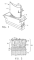
- Figure 1 is a perspective view of a high pressure turbine blade.
- Figure 2 schematically represents a cross-sectional view of the blade of Figure 1 along line 2--2, and shows a thermal barrier coating system on the blade in accordance with the invention.
- Figures 3 and 4 are microphotographs of thermal barrier coatings deposited in accordance with this invention and the prior art, respectively, in the as-deposited condition.
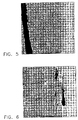
- Figures 5 and 6 are microphotographs of the thermal barrier coatings of Figures 3 and 4, respectively, following heat treatment at about 1200°C for about two hours.
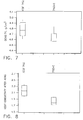
- Figures 7 and 8 are graphs comparing the thermal conductivities and densities, respectively, of thermal barrier coatings formed in accordance with the prior art and the present invention.
- the present invention is generally applicable to components subjected to high temperatures, and particularly to components such as the high and low pressure turbine nozzles and blades, shrouds, combustor liners and augmentor hardware of gas turbine engines.
- An example of a high pressure turbine blade 10 is shown in Figure 1.
- the blade 10 generally includes an airfoil 12 against which hot combustion gases are directed during operation of the gas turbine engine, and whose surface is therefore subjected to hot combustion gases as well as attack by oxidation, corrosion and erosion.
- the airfoil 12 is protected from its hostile operating environment by a thermal barrier coating (TBC) system schematically depicted in Figure 2.
- TBC thermal barrier coating
- the airfoil 12 is anchored to a turbine disk (not shown) with a dovetail 14 formed on a root section 16 of the blade 10.
- Cooling passages 18 are present in the airfoil 12 through which bleed air is forced to transfer heat from the blade 10. While the advantages of this invention will be described with reference to the high pressure turbine blade 10 shown in Figure 1, the teachings of this invention are generally applicable to any component on which a thermal barrier coating may be used to protect the component from a high temperature environment.
- the TBC system 20 is represented in Figure 2 as including a metallic bond coat 24 that overlies the surface of a substrate 22, the latter of which is typically a superalloy and the base material of the blade 10.
- the bond coat 24 is preferably an aluminum-rich composition, such as an overlay coating of an MCrAIX alloy or a diffusion coating such as a diffusion aluminide or a diffusion platinum aluminide of a type known in the art.
- Aluminum-rich bond coats of this type develop an aluminum oxide (alumina) scale 28, which is grown by oxidation of the bond coat 24.
- the alumina scale 28 chemically bonds a thermal-insulating material, or TBC 26, to the bond coat 24 and substrate 22.
- the TBC 26 of Figure 2 is represented as having a strain-tolerant microstructure of columnar grains 30.
- such columnar microstructures can be achieved by depositing the TBC 26 using a physical vapor deposition technique, such as EBPVD. While much of the following discussion will focus on columnar TBC of the type represented by Figure 2, the invention is also believed to be applicable to noncolumnar TBC deposited by such methods as plasma spraying, including air plasma spraying (APS).
- a TBC of this type is in the form of molten "splats,” resulting in a microstructure characterized by irregular flattened grains and a degree of inhomogeneity and porosity.
- a preferred thermal-insulating material for the TBC 26 is based on binary yttria-stabilized zirconia (YSZ), and particularly zirconia partially stabilized by yttria.
- Other ceramic materials could also be used with this invention, such as zirconia fully stabilized by yttria, nonstabilized zirconia, or zirconia partially or fully stabilized by ceria, magnesia, scandia and/or other oxides.
- a particularly suitable material for the TBC is YSZ containing about 4 to about 8 weight percent yttria.
- the TBC 26 is deposited to a thickness that is sufficient to provide the required thermal protection for the underlying substrate 22 and blade 10, generally on the order of about 75 to about 300 micrometers.
- a first aspect of the present invention is to increase the amount of as-deposited open porosity within the TBC 26.
- a second aspect of the invention is to maintain or increase the amount of porosity in the TBC microstructure and to stabilize the TBC microstructure during high temperature excursions that would otherwise cause grain growth (coarsening), sintering and pore redistribution, leading to coarsening and/or elimination of the desirable defects and pores 32.
- both of these aspects can be achieved with this invention through the co-deposition of elemental carbon during the coating deposition process.
- an increased amount of fine open porosity can be produced in the as-deposited TBC 26 by co-depositing elemental carbon and the insulating material (e.g., YSZ) of the TBC 26, and additional fine porosity forms during subsequent exposures to high temperatures as a result of insoluble carbon-containing gases evolving from the carbon and then becoming entrapped within the TBC 26 as a result of partial sintering of the TBC 26.
- the second aspect can be achieved by directly incorporating an insoluble gas into the TBC 26 through an infiltration process, and then partially sintering the TBC 26 to entrap the infiltrated gas.
- a preferred method for co-depositing carbon and the thermal-insulating material of the TBC 26 is by the evaporation of one or more ingots of the thermal-insulating material and carbon and/or a carbon compound.
- a suitable carbon source is graphite
- suitable carbon compounds include zirconium carbide (ZrC), titanium carbide (TiC), tantalum carbide (TaC), and molybdenum carbide (Mo 2 C).
- ZrC zirconium carbide
- TiC titanium carbide
- TaC tantalum carbide
- Mo 2 C molybdenum carbide
- "primary" porosity is believed to be created surrounding deposited elemental carbon clusters (and possibly clusters of carbides, carbonitrides, nitrides, etc., all of which are insoluble in YSZ) during EBPVD as a result of zirconia vapor flux being blocked from the immediate vicinity of the second phase clusters.
- Another benefit of co-deposition of carbon clusters (and possibly carbide clusters) by EBPVD has been observed to be the formation of many additional interfaces associated with sub-grain boundaries, possibly due to what appears to be related to the presence of carbon promoting the nucleation of new sub-grains and inhibiting diffusion processes of grain growth.
- Open porosity levels observed within TBC deposited in accordance with this invention are well in excess of YSZ TBC deposited from an identical YSZ source material (minus the carbon source) under identical conditions. While YSZ TBC is typically deposited by EBPVD to have open porosity levels of not more than about 15 to 20 volume percent, open porosity levels on the order of at least about 25 volume percent are believed to be possible with the present invention, with typical open porosity levels being about 30 to about 35 volume percent.
- Fine "secondary" porosity occurs with this invention as a result of elemental carbon (and possibly carbides) reacting with oxygen to form carbon monoxide (CO) and/or another carbon-containing gas (e.g., carbon dioxide; CO 2 ) during high temperature excursions (e.g., above about 950°C).
- CO carbon monoxide
- another carbon-containing gas e.g., carbon dioxide; CO 2
- micropores very fine pores
- the entrapped gas is believed to counteract surface tension energies that are the driving force for pore coarsening (coalescing) during sintering. Therefore, in addition to reducing the density and thermal conductivity of the TBC 26, the added fine porosity made possible with this invention is thermally stable, i.e., not susceptible to shrinkage.
- Suitable gases for this purpose include carbon monoxide, carbon dioxide, sulfur dioxide, nitrogen and argon, which can be introduced into the TBC 26 during deposition of the TBC 26 or during a post-deposition process.
- a heating step must be intentionally performed to cause at least partial sintering of the TBC 26 in order to close the open porosity that allowed the gas to permeate the TBC 26, thereby preventing the gas from escaping.
- the TBC 26 could be placed under vacuum in a chamber, and then the insoluble gas introduced into the chamber to infiltrate the open porosity of the TBC 26.
- the porosity would then be closed by heating the TBC 26 (preferably in an atmosphere of the insoluble gas) to a temperature of about 950°C or more for a YSZ TBC. Once closed, the pores containing the gas would be stabilized against further densification by the pressure of the entrapped insoluble gas.
- a plasma-sprayed TBC is deposited as molten "splats" that produces a grain structure characterized by irregular flattened grains surrounded by inhomogeneous porosity.
- an effective amount of porosity can be maintained to stabilize the TBC microstructure during high temperature excursions by co-depositing powders of elemental carbon or carbon-based compounds and the TBC material, such as by simultaneously spraying graphite and YSZ powders or spraying a graphite-coated YSZ powder.
- an insoluble carbon-containing gas would then be evolved and some of the existing open porosity closed during a subsequent thermal treatment that is sufficient to partially sinter the TBC.
- an insoluble gas could be directly incorporated into the TBC 26 in a post-deposition process as described above. In either case, the process and result differs from that of U.S. Patent No. 5,906,895 to Hamada et al., in that Hamada et al. teach forming a plasma-sprayed TBC that either contains splats of carbides or another high temperature compound, or is infiltrated with a feed gas to form a coating of carbides (or another high temperature compound) on the inter-splat boundaries of the TBC. Neither of these TBC's could contain entrapped gas because of the open porous nature of the plasma-sprayed TBC.
- YSZ TBC was deposited by EBPVD on specimens formed of the superalloy René N5 on which a platinum aluminide (PtAl) bond coat had been deposited. Some of the specimens were coated by co-evaporating separate ingots of graphite and 7%YSZ (zirconia stabilized by about 7 wt.% yttria).
- the graphite ingot included a tungsten cap which, during EBPVD, forms a molten surface pool through which carbon evaporates in accordance with U.S. Patent No. 5,296,274 to Movchan et al.
- the specimens were loaded into a coating chamber so as to be supported above the ingots, and the chamber evacuated to achieve a partial vacuum of about 4.7x10 -4 to about 6.6x10 -4 Torr (about 6.3x10 -4 to about 8.8x10 -4 mbar).
- the chamber was then heated to a temperature of between about 900°C and 1000°C and, while the specimens were rotated at a rate of about 25 rpm, two electron beam guns were operated at power levels of about 19.5 kW and 23 kW to project electron beams onto the YSZ and graphite ingots, respectively, so as to melt the ingot surfaces and produce a vapor cloud containing zirconia, zirconium monoxide, zirconium, yttrium, yttria, yttria suboxides, oxygen and carbon.
- the vapors deposited (condensed) on the specimen surfaces to form TBC's whose thicknesses were on the order of about 150 micrometers.
- Each of the resulting coatings contained a dispersion of carbon (solid graphite) and possibly zirconium carbide, which congregated at the defects, pores and sub-grains (interfaces within the grains) of the YSZ microstructure during growth of the individual grains.
- the amount of carbon deposited was determined by the position of each specimen relative to the graphite pool, with those closer to the graphite pool receiving a higher concentration of carbon than those closer to the YSZ pool. Additional specimens were coated in the same manner described above, but with only an ingot of 7%YSZ being evaporated to deposit a conventional 7%YSZ TBC.
- Figures 3 and 4 are 5000x microphotographs of one of each of the as-coated 7%YSZ+C and 7%YSZ specimens, respectively.
- the open porosity of the 7%YSZ+C specimens was measured to be about 32 volume percent, as compared to about 12 volume percent for the conventional 7%YSZ specimens.
- the specimens then underwent aging at about 1200°C for about two hours.
- Figures 5 and 6 are 5000x microphotographs of aged 7%YSZ and 7%YSZ+C specimens, respectively.
Landscapes
- Chemical & Material Sciences (AREA)
- Engineering & Computer Science (AREA)
- Materials Engineering (AREA)
- Mechanical Engineering (AREA)
- Inorganic Chemistry (AREA)
- Chemical Kinetics & Catalysis (AREA)
- Metallurgy (AREA)
- Organic Chemistry (AREA)
- General Engineering & Computer Science (AREA)
- Ceramic Engineering (AREA)
- Turbine Rotor Nozzle Sealing (AREA)
- Chemical Vapour Deposition (AREA)
Applications Claiming Priority (2)
| Application Number | Priority Date | Filing Date | Title |
|---|---|---|---|
| UA02010240 | 2002-01-09 | ||
| UA2002010240 | 2002-01-09 |
Publications (3)
| Publication Number | Publication Date |
|---|---|
| EP1327698A2 true EP1327698A2 (de) | 2003-07-16 |
| EP1327698A3 EP1327698A3 (de) | 2004-05-12 |
| EP1327698B1 EP1327698B1 (de) | 2012-03-14 |
Family
ID=34421054
Family Applications (1)
| Application Number | Title | Priority Date | Filing Date |
|---|---|---|---|
| EP20030250128 Expired - Lifetime EP1327698B1 (de) | 2002-01-09 | 2003-01-09 | Thermisch stabilisierte Wärmedämmschicht und Verfahren zu deren Herstellung |
Country Status (2)
| Country | Link |
|---|---|
| US (1) | US6998172B2 (de) |
| EP (1) | EP1327698B1 (de) |
Cited By (3)
| Publication number | Priority date | Publication date | Assignee | Title |
|---|---|---|---|---|
| EP1580296A3 (de) * | 2004-03-22 | 2005-10-05 | United Technologies Corporation | Verfahren zur Herstellung einer porösen Beschichtung |
| RU2280096C1 (ru) * | 2004-11-29 | 2006-07-20 | Федеральное государственное унитарное предприятие "Всероссийский научно-исследовательский институт авиационных материалов" (ФГУП "ВИАМ") | Способ защиты лопаток газовых турбин |
| EP3492622A1 (de) * | 2017-12-04 | 2019-06-05 | General Electric Company | Verfahren zur formung einer porösen wärmebarrierenbeschichtung |
Families Citing this family (7)
| Publication number | Priority date | Publication date | Assignee | Title |
|---|---|---|---|---|
| WO2004048632A2 (en) * | 2002-11-21 | 2004-06-10 | University Of Virginia Patent Foundation | Bond coat for a thermal barrier coating systemand related method thereof |
| US7824744B2 (en) * | 2003-12-16 | 2010-11-02 | General Electric Company | Process and apparatus for depositing a ceramic coating |
| US20060068189A1 (en) * | 2004-09-27 | 2006-03-30 | Derek Raybould | Method of forming stabilized plasma-sprayed thermal barrier coatings |
| DE112010001693T5 (de) | 2009-04-20 | 2013-01-03 | Borgwarner Inc. | Isolierender abstandshalter für kugellagereinsatz |
| WO2013068315A1 (en) | 2011-11-10 | 2013-05-16 | Alstom Technology Ltd | High temperature thermal barrier coating |
| KR102113356B1 (ko) * | 2011-12-19 | 2020-05-20 | 프랙스에어 에스.티. 테크놀로지, 인코포레이티드 | 열적 및 환경적 장벽 피복의 제조를 위한 수성 슬러리 및 그의 제조 및 적용 방법 |
| CN111041428B (zh) * | 2019-12-17 | 2021-02-26 | 北京航空航天大学 | 基于eb-pvd制备纳米碳化物增强基体稳定性的方法 |
Family Cites Families (11)
| Publication number | Priority date | Publication date | Assignee | Title |
|---|---|---|---|---|
| WO1990013683A1 (fr) | 1989-05-10 | 1990-11-15 | Institut Elektrosvarki Imeni E.O.Patona Akademii Nauk Ukrainskoi Ssr | Procede d'obtention de materiaux contenant du carbone |
| JP2664771B2 (ja) | 1989-05-16 | 1997-10-22 | 三菱マテリアル株式会社 | プラズマ溶射セラミックス皮膜のhip処理法 |
| US5418003A (en) | 1993-09-10 | 1995-05-23 | General Electric Company | Vapor deposition of ceramic materials |
| US5512382A (en) * | 1995-05-08 | 1996-04-30 | Alliedsignal Inc. | Porous thermal barrier coating |
| US5683825A (en) | 1996-01-02 | 1997-11-04 | General Electric Company | Thermal barrier coating resistant to erosion and impact by particulate matter |
| JPH1088368A (ja) | 1996-09-19 | 1998-04-07 | Toshiba Corp | 遮熱コーティング部材およびその作製方法 |
| JP3302589B2 (ja) * | 1997-02-06 | 2002-07-15 | 株式会社日立製作所 | セラミック被覆ガスタービン動翼 |
| FR2779448B1 (fr) * | 1998-06-04 | 2000-12-15 | Snecma | Revetement ceramique a faible conductivite thermique et de type barriere thermique, procede de depot d'un tel revetement ceramique, et piece metallique protegee par ce revetement ceramique |
| FR2784120B1 (fr) | 1998-10-02 | 2000-11-03 | Snecma | Revetement de barriere thermique a faible conductivite thermique, piece metallique protegee par ce revetement, procede de depot de ce revetement |
| US6492038B1 (en) * | 2000-11-27 | 2002-12-10 | General Electric Company | Thermally-stabilized thermal barrier coating and process therefor |
| UA74150C2 (uk) * | 2002-01-09 | 2005-11-15 | Дженерал Електрік Компані | Спосіб формування покриття для створення теплового бар'єра та покриття для створення теплового бар'єра |
-
2002
- 2002-08-16 US US10/064,791 patent/US6998172B2/en not_active Expired - Fee Related
-
2003
- 2003-01-09 EP EP20030250128 patent/EP1327698B1/de not_active Expired - Lifetime
Cited By (4)
| Publication number | Priority date | Publication date | Assignee | Title |
|---|---|---|---|---|
| EP1580296A3 (de) * | 2004-03-22 | 2005-10-05 | United Technologies Corporation | Verfahren zur Herstellung einer porösen Beschichtung |
| RU2280096C1 (ru) * | 2004-11-29 | 2006-07-20 | Федеральное государственное унитарное предприятие "Всероссийский научно-исследовательский институт авиационных материалов" (ФГУП "ВИАМ") | Способ защиты лопаток газовых турбин |
| EP3492622A1 (de) * | 2017-12-04 | 2019-06-05 | General Electric Company | Verfahren zur formung einer porösen wärmebarrierenbeschichtung |
| CN109865645A (zh) * | 2017-12-04 | 2019-06-11 | 通用电气公司 | 形成多孔热屏障涂层的方法 |
Also Published As
| Publication number | Publication date |
|---|---|
| US20030129378A1 (en) | 2003-07-10 |
| EP1327698A3 (de) | 2004-05-12 |
| EP1327698B1 (de) | 2012-03-14 |
| US6998172B2 (en) | 2006-02-14 |
Similar Documents
| Publication | Publication Date | Title |
|---|---|---|
| EP1327704B1 (de) | Thermische Schutztschicht und Verfahren zur deren Herstellung | |
| US6544665B2 (en) | Thermally-stabilized thermal barrier coating | |
| US6979498B2 (en) | Strengthened bond coats for thermal barrier coatings | |
| US6960395B2 (en) | Ceramic compositions useful for thermal barrier coatings having reduced thermal conductivity | |
| US7364802B2 (en) | Ceramic compositions useful in thermal barrier coatings having reduced thermal conductivity | |
| JP3081611B2 (ja) | セラミックコーティングを有する金属製の基体を含む金属製部材及び金属製の基体に断熱性を与えるための方法 | |
| EP1550645B1 (de) | Keramische Zusammensetzungen für Wärmedämmschichten stabilisiert in der kubischen kristallinen Phase | |
| EP1209321B1 (de) | Thermisch stabilisierte Wärmedämmschicht und deren Aufbringung | |
| US6689487B2 (en) | Thermal barrier coating | |
| US20030152797A1 (en) | Method of forming a coating resistant to deposits and coating formed thereby | |
| US8100083B2 (en) | Process and apparatus for depositing a ceramic coating | |
| US20100266417A1 (en) | Bond coat with low deposited aluminum level and method therefore | |
| EP1327698B1 (de) | Thermisch stabilisierte Wärmedämmschicht und Verfahren zu deren Herstellung | |
| US20050202168A1 (en) | Thermally-stabilized thermal barrier coating and process therefor | |
| US20030118873A1 (en) | Stabilized zirconia thermal barrier coating with hafnia |
Legal Events
| Date | Code | Title | Description |
|---|---|---|---|
| PUAI | Public reference made under article 153(3) epc to a published international application that has entered the european phase |
Free format text: ORIGINAL CODE: 0009012 |
|
| AK | Designated contracting states |
Designated state(s): AT BE BG CH CY CZ DE DK EE ES FI FR GB GR HU IE IT LI LU MC NL PT SE SI SK TR |
|
| AX | Request for extension of the european patent |
Extension state: AL LT LV MK RO |
|
| PUAL | Search report despatched |
Free format text: ORIGINAL CODE: 0009013 |
|
| AK | Designated contracting states |
Kind code of ref document: A3 Designated state(s): AT BE BG CH CY CZ DE DK EE ES FI FR GB GR HU IE IT LI LU MC NL PT SE SI SK TR |
|
| AX | Request for extension of the european patent |
Extension state: AL LT LV MK RO |
|
| RIC1 | Information provided on ipc code assigned before grant |
Ipc: 7F 01D 5/02 B Ipc: 7C 23C 14/08 B Ipc: 7F 01D 5/28 B Ipc: 7C 23C 14/58 B Ipc: 7C 23C 14/22 B Ipc: 7C 23C 14/06 A |
|
| 17P | Request for examination filed |
Effective date: 20041112 |
|
| AKX | Designation fees paid |
Designated state(s): DE FR GB NL |
|
| 17Q | First examination report despatched |
Effective date: 20050301 |
|
| 17Q | First examination report despatched |
Effective date: 20050301 |
|
| GRAP | Despatch of communication of intention to grant a patent |
Free format text: ORIGINAL CODE: EPIDOSNIGR1 |
|
| GRAS | Grant fee paid |
Free format text: ORIGINAL CODE: EPIDOSNIGR3 |
|
| GRAA | (expected) grant |
Free format text: ORIGINAL CODE: 0009210 |
|
| AK | Designated contracting states |
Kind code of ref document: B1 Designated state(s): DE FR GB NL |
|
| REG | Reference to a national code |
Ref country code: GB Ref legal event code: FG4D |
|
| REG | Reference to a national code |
Ref country code: NL Ref legal event code: T3 |
|
| REG | Reference to a national code |
Ref country code: DE Ref legal event code: R096 Ref document number: 60340254 Country of ref document: DE Effective date: 20120510 |
|
| PLBE | No opposition filed within time limit |
Free format text: ORIGINAL CODE: 0009261 |
|
| STAA | Information on the status of an ep patent application or granted ep patent |
Free format text: STATUS: NO OPPOSITION FILED WITHIN TIME LIMIT |
|
| 26N | No opposition filed |
Effective date: 20121217 |
|
| REG | Reference to a national code |
Ref country code: DE Ref legal event code: R097 Ref document number: 60340254 Country of ref document: DE Effective date: 20121217 |
|
| PGFP | Annual fee paid to national office [announced via postgrant information from national office to epo] |
Ref country code: FR Payment date: 20130211 Year of fee payment: 11 Ref country code: GB Payment date: 20130125 Year of fee payment: 11 Ref country code: DE Payment date: 20130129 Year of fee payment: 11 |
|
| PGFP | Annual fee paid to national office [announced via postgrant information from national office to epo] |
Ref country code: NL Payment date: 20130125 Year of fee payment: 11 |
|
| REG | Reference to a national code |
Ref country code: DE Ref legal event code: R119 Ref document number: 60340254 Country of ref document: DE |
|
| REG | Reference to a national code |
Ref country code: NL Ref legal event code: V1 Effective date: 20140801 |
|
| GBPC | Gb: european patent ceased through non-payment of renewal fee |
Effective date: 20140109 |
|
| PG25 | Lapsed in a contracting state [announced via postgrant information from national office to epo] |
Ref country code: DE Free format text: LAPSE BECAUSE OF NON-PAYMENT OF DUE FEES Effective date: 20140801 Ref country code: NL Free format text: LAPSE BECAUSE OF NON-PAYMENT OF DUE FEES Effective date: 20140801 |
|
| REG | Reference to a national code |
Ref country code: FR Ref legal event code: ST Effective date: 20140930 |
|
| REG | Reference to a national code |
Ref country code: DE Ref legal event code: R119 Ref document number: 60340254 Country of ref document: DE Effective date: 20140801 |
|
| PG25 | Lapsed in a contracting state [announced via postgrant information from national office to epo] |
Ref country code: GB Free format text: LAPSE BECAUSE OF NON-PAYMENT OF DUE FEES Effective date: 20140109 Ref country code: FR Free format text: LAPSE BECAUSE OF NON-PAYMENT OF DUE FEES Effective date: 20140131 |