EP1327733A2 - Module pour un échafaudage en porte-à-faux - Google Patents
Module pour un échafaudage en porte-à-faux Download PDFInfo
- Publication number
- EP1327733A2 EP1327733A2 EP03000795A EP03000795A EP1327733A2 EP 1327733 A2 EP1327733 A2 EP 1327733A2 EP 03000795 A EP03000795 A EP 03000795A EP 03000795 A EP03000795 A EP 03000795A EP 1327733 A2 EP1327733 A2 EP 1327733A2
- Authority
- EP
- European Patent Office
- Prior art keywords
- module
- piece
- cross
- assembly component
- upright
- Prior art date
- Legal status (The legal status is an assumption and is not a legal conclusion. Google has not performed a legal analysis and makes no representation as to the accuracy of the status listed.)
- Withdrawn
Links
- 230000000284 resting effect Effects 0.000 claims abstract description 12
- 125000006850 spacer group Chemical group 0.000 claims description 12
- 230000013011 mating Effects 0.000 claims description 7
- 238000004873 anchoring Methods 0.000 description 2
- 238000012423 maintenance Methods 0.000 description 2
- 238000000034 method Methods 0.000 description 2
- 229910052782 aluminium Inorganic materials 0.000 description 1
- XAGFODPZIPBFFR-UHFFFAOYSA-N aluminium Chemical compound [Al] XAGFODPZIPBFFR-UHFFFAOYSA-N 0.000 description 1
- 230000000903 blocking effect Effects 0.000 description 1
- 238000010276 construction Methods 0.000 description 1
- 230000001419 dependent effect Effects 0.000 description 1
- 238000009434 installation Methods 0.000 description 1
- 229910052751 metal Inorganic materials 0.000 description 1
- 239000002184 metal Substances 0.000 description 1
- 239000000203 mixture Substances 0.000 description 1
- 239000011295 pitch Substances 0.000 description 1
- 238000007493 shaping process Methods 0.000 description 1
Images


Classifications
-
- E—FIXED CONSTRUCTIONS
- E04—BUILDING
- E04G—SCAFFOLDING; FORMS; SHUTTERING; BUILDING IMPLEMENTS OR AIDS, OR THEIR USE; HANDLING BUILDING MATERIALS ON THE SITE; REPAIRING, BREAKING-UP OR OTHER WORK ON EXISTING BUILDINGS
- E04G21/00—Preparing, conveying, or working-up building materials or building elements in situ; Other devices or measures for constructional work
- E04G21/32—Safety or protective measures for persons during the construction of buildings
- E04G21/3204—Safety or protective measures for persons during the construction of buildings against falling down
- E04G21/3219—Means supported by the building wall, e.g. security consoles
-
- E—FIXED CONSTRUCTIONS
- E04—BUILDING
- E04G—SCAFFOLDING; FORMS; SHUTTERING; BUILDING IMPLEMENTS OR AIDS, OR THEIR USE; HANDLING BUILDING MATERIALS ON THE SITE; REPAIRING, BREAKING-UP OR OTHER WORK ON EXISTING BUILDINGS
- E04G3/00—Scaffolds essentially supported by building constructions, e.g. adjustable in height
- E04G3/20—Scaffolds essentially supported by building constructions, e.g. adjustable in height supported by walls
-
- E—FIXED CONSTRUCTIONS
- E04—BUILDING
- E04G—SCAFFOLDING; FORMS; SHUTTERING; BUILDING IMPLEMENTS OR AIDS, OR THEIR USE; HANDLING BUILDING MATERIALS ON THE SITE; REPAIRING, BREAKING-UP OR OTHER WORK ON EXISTING BUILDINGS
- E04G5/00—Component parts or accessories for scaffolds
- E04G5/04—Means for fastening, supporting, or bracing scaffolds on or against building constructions
- E04G5/046—Means for fastening, supporting, or bracing scaffolds on or against building constructions for fastening scaffoldings on walls
-
- E—FIXED CONSTRUCTIONS
- E04—BUILDING
- E04G—SCAFFOLDING; FORMS; SHUTTERING; BUILDING IMPLEMENTS OR AIDS, OR THEIR USE; HANDLING BUILDING MATERIALS ON THE SITE; REPAIRING, BREAKING-UP OR OTHER WORK ON EXISTING BUILDINGS
- E04G5/00—Component parts or accessories for scaffolds
- E04G5/06—Consoles; Brackets
- E04G5/062—Consoles; Brackets specially adapted for attachment to building walls
Definitions
- the present invention concerns a module for cantilevered scaffolding of the provisional type employed with the function of a parapet in the execution of works done on elevated structures such as for example buildings.
- module for scaffolding according to the invention can also be used in association with other elevated structures such as bridges, dams, large containers, supports for antennas or suchlike.
- Modular cantilevered scaffoldings made by means of a plurality of modules are known: they are used, mainly with the function of a provisional parapet, in the field of works for the construction and/or maintenance of buildings, for example in the case of work to be done on coverings, such as roofs protruding from the vertical walls of buildings.
- Such scaffoldings are substantially divided into two types, both of which have various disadvantages.
- a first type concerns scaffoldings which are anchored to the building by means of screw anchors or similar means, attached by means of making holes in the vertical walls.
- Such scaffoldings cannot be used in several circumstances such as for example when the roofs have cornices, or pitches, with great overhangs, or in cases when it is necessary to make the anchorage on decorated or finished surfaces.
- Cantilevered scaffoldings of the second type are anchored to the building by vice means.
- the disadvantages are the lack of security and above all the considerable bulk of the anchoring system which prevents, in particular cases, the completion of the works, especially those which have to be made on the roof.
- the scaffolding is attached by vices to the cornice or the overhanging part of the roof, but this prevents free access to the edge of the roof where there is the gutter. The same happens in the event of maintenance of the covering of the roof.
- Modules for cantilevered scaffolding of a conventional type therefore allow only one method of anchorage to the structure and hence cannot be used universally, which entails the need for users to equip themselves with a plurality of different modular systems according to the circumstances in which they have to operate.
- the purpose of the invention is to provide a module for cantilevered scaffoldings of a provisional type which is simple, versatile and not bulky, so that it can be used substantially in association with any type of structure or civil or industrial building, with different anchoring methods, allowing in all circumstances easy access for the workers to the site of the work.
- Another purpose of the invention is to achieve a safe and reliable module for cantilevered scaffoldings which comprises a limited number of components and is practical and quick to assemble, dis-assemble and reconfigure in its different conditions of use.
- the module for cantilevered scaffoldings according to the invention comprises two base components which can be selectively associated with a plurality of assembly and/or accessory components according to the type of anchorage to be made on the building, or structure, with which the scaffolding has to be associated.
- the base components are: a cross-piece, arranged substantially horizontal during use, and an upright, arranged substantially vertical during use and provided with at least a supporting bracket, or other analogous element, advantageously two or more, distanced vertically, for longitudinal blocking and containing elements with a safety function, such as boards, planks, metal plates, staffs or similar.
- the cross-piece is provided with at least a first seating for a first assembly component defining an anchorage of the through type on a structural part of the building, to be more exact on a protruding segment of the covering, and a second seating for a second assembly component defining an anchorage resting on one surface of the building, for example on a segment of vertical or substantially vertical wall.
- one and/or the other assembly component is/are used, keeping the other components of the module substantially unchanged.
- the presence of a through anchorage on the protruding segment of the covering allows to assemble the module according to the invention substantially irrespective of the width of the cantilevered part of the covering, therefore guaranteeing a stable anchorage in any condition.
- the resting anchorage is used, or even the resting anchorage together with the through anchorage, thus increasing the flexibility of use of the module according to the invention.
- the resting anchorage can be used in combination with the through anchorage also when there are particular conditions of stress, or on wall structures having little or difficult gripping capacity.
- the module comprises accessory components able to improve the stability and positioning of the scaffolding to be made, and to improve its adaptability and capacity to adjust to the different conditions in which it finds itself operating, in any case keeping high standards of safety for the operator and ensuring easy and rapid assembly.
- accessory components consist at least of spacer means and brace means, with relative adjustment means and means to attach them to the cross-piece and/or upright.
- the module for cantilevered scaffoldings according to the invention not only provides a limited number of base components which make it extremely practical and economical, but also has characteristics of considerable versatility and can therefore be used universally, substantially in any field of installation.
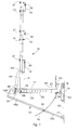
- a module 10 for cantilevered scaffoldings comprises a plurality of components 11-20 which can be selectively associated with each other in differentiated fashion so as to make cantilevered scaffoldings of different compositions according to the type of building 21 with which they have to be associated.
- a plurality of such modules 10 are associated in series with the building 21 and aligned with each other, so as to create a modular structure which develops for a desired perimeter segment of the zone in which work is to be carried out.
- the module 10 comprises two base components which are always used: a cross-piece 11 and an upright 12 with C-shaped brackets 13.
- the brackets 13 are made of terminally threaded bars and are used to attach the boards or planks, not shown here, which have a containing function for the safety of the operators; the bracket 13 located at the lowest point is bigger than the others in order to accommodate higher planks functioning as a foot protection element.
- the cross-piece 11 (figs. 2a and 2b) is the component which is always anchored to the building 21 and consists of a tubular profile inserted into a mating through aperture 27 made on the lower part of the upright 12 and defined by two blades 52 welded to the lower part of the upright 12 (fig. 3a).
- the cross-piece 11 has a square tubular profile 51 welded, during use, vertically and located in proximity with its rear end, that is, the end facing towards the building 21; the square tubular profile is closed at the bottom part by a U-shaped profile 57 on which is mounted rotatable a threaded bar which is arranged inside the square tubular profile 51 and which can be driven by means of a manoeuvring rod 58 for the function described hereafter.
- the cross-piece 11 also has a round tubular profile 61 with a vertical axis, arranged during use in its rear part (fig. 2b) and defining a through hole 26.
- the function of the round tubular profile 61 is to contain a threaded bar 20 for through assembly with the protruding part of the roof, as will be described in more detail hereafter.
- the first hole 22a is located substantially at its front end, the other four 22b-22e are arranged in its rear part, and serve for the assembly of assembly and/or accessory components, as will be described hereafter.
- the upright 12 (figs. 3a and 3b) also consists of a tubular profile and can be selectively clamped in the desired position along the cross-piece 11, in this case by means of a threaded pin 28 which is made to pass through any one as chosen of said holes 25 and through mating holes 62 made on said parallel blades 52 in the lower part of the upright 12 itself.
- a threaded pin 28 which is made to pass through any one as chosen of said holes 25 and through mating holes 62 made on said parallel blades 52 in the lower part of the upright 12 itself.
- One of the two holes 62 present in said blades 52 is threaded in order to clamp the pin 28 by means of nut and bolt.
- An adjustment rod 54 is associated with the upright 12 and allows to adjust the inclination of the upright 12, with extreme precision, with respect to the cross-piece 11.
- the adjustment rod 54 is attached with its upper end, by means of a substantially horizontal pin 53, to the upright 12 and is connected to the cross-piece 11 by means of two blades 55 present at its lower end.
- the upright 12 has a series of horizontal through holes 29, advantageously aligned with each other and equidistant, in correspondence with which the brackets 13 are attached in the desired position.
- the brackets 13 in fact, have threaded ends 13a which can have a variable interaxis, as shown in fig. 1, but in any case equal to a multiple of the interaxis between the through holes 29. In this way the brackets 13 are inserted at different heights inside the through holes 29 with the threaded ends 13a which, protruding from the upright 12, allow suitable wing nuts 31 to be screwed in, which thus achieve the clamping thereof.
- Each bracket 13 thus defines a seating 30 inside which a relative longitudinal element to contain the scaffolding can be inserted, such as for example a wooden shaft or an aluminum rod.
- the flange 14 (figs. 9a and 9b) comprises two angle bars 14b provided on one side with holes for means to anchor the flange to the building 21 and on the other side with respective through holes 32, aligned with each other.
- the two angle bars 14b are joined by a plate 14a and between them there is the cross-piece 11 with the horizontal hole 22e aligned with the holes 32.
- the flange 14 and the cross-piece 11 can be positioned at a variable angle, according to the specific requirements of the application, for example to rest on inclined cornices 47 (fig. 20), and can be reciprocally clamped by means of a screw element, such as for example a bolt, inserted inside the holes 22e and 32.
- a screw element such as for example a bolt
- the remaining components 15-20 of the module 10, which can be used or not according to the circumstances, comprise: a brace 15, an adjustment rod 16, a second flange 17, a first 18 and a second 19 spacer and an anchorage bar 20.
- the second flange 17 (figs. 10a and 10b) comprises two angle bars 17b joined by a plate 17a and provided on one side with holes for means to anchor the flange to the building 21 and on the other side with respective through holes 35, aligned with each other.
- the two flanges 14 and 17 can be anchored to or merely rested on the building 21, according to the type of scaffolding to be made.
- the brace 15 consists of two tubular profiles, inner 15a and outer 15b, telescopically associated together and able to be selectively clamped in the desired axial position by means of a wing nut 33 mounted on the outer tubular profile 15b.
- the latter has the free end conformed as a fork with a hole 34 able to be coupled with the horizontal hole 22a of the cross-piece 11, while the inner tubular profile 15a has a through hole 36 at the free end.
- the brace 15 is assembled by constraining the free end of the outer tubular profile 15b to the front end of the cross-piece 11, by means of a clamping pin inserted through between the holes 22a and 34, and the free end of the inner tubular profile 15a to the second flange 17, by means of a clamping pin arranged through between the holes 35 and 36. In this way, the second flange 17 and the brace 15 can also be positioned and reciprocally clamped at various angles.
- the adjustment rod 16 with a curved conformation, has a hook-like shaping 16a at its upper end which can be inserted into the horizontal hole 22d of the cross-piece 11 and clamped with respect to the latter by means of a pin inserted into a mating hole made on the same upper end.
- the lower end on the contrary, can be inserted and slide inside a through hole made on the outer tubular profile 15b of the brace 15, in correspondence with the wing nut 33 by means of which the adjustment rod 16 and the inner tubular profile 15a are clamped at the desired point.
- the adjustment rod 16 can be installed to connect the cross-piece 11 to the brace 15, whatever the position assumed by the latter.
- the spacers 18 and 19 can be associated substantially orthogonally with the cross-piece 11 and are able to act through interference on an upper supporting surface, to make the cross-piece 11 more stable and improve the horizontal positioning thereof.
- the first spacer 18 comprises a square tubular profile 63 arranged vertically during use inside the square tubular profile 51.
- the square tubular profile 63 has at the lower part a bushing 40 on which the threaded bar 37 is able to be screwed.
- the upper end of the square tubular profile 63 is connected to a support 38, and an L-shaped profile 39 is associated to the upper part thereof and arranged transversely with respect to the square tubular profile 63. Acting on the threaded bar 37 by means of the manoeuvring rod 58 it is possible to adjust the spacer 18 in height according to the requirements of resting on the lower part of the protrusion of the roof (figs.
- the support 38 is advantageously pivoting around a pin 60 with respect to the square tubular profile 63 so that it can also adapt to the different inclinations of the protrusion of the roof.
- the second spacer 19 comprises a support 41 above which a buffer 43 is assembled.
- the support 41 has two blades 42 which have respective holes 59, aligned with each other, in order to attach the support 41 to the cross-piece 11 by means of nuts and bolts which are inserted into the holes with the horizontal axis 22b and 22c.
- the anchor bar 20, of the threaded type functions as a connection between the cross-piece 11 and a protruding part of the building 21, such as the protruding part of a slope 46 or a cornice 47 and serves as an assembly component of a through type to assemble the whole module 10 to the roof of the building 21.
- the anchor bar 20 In order to install the anchor bar 20 it is necessary to prepare a through hole on the protruding part 46 or 47 of the building 21.
- the anchor bar 20 is then inserted through into the vertical axis hole 26 of the cross-piece 11 and into the hole of the protruding part 46 or 47; it is then clamped on the latter and on the cross-piece 11, in this case with two screw nuts 48 and 49.
- the anchor bar 20 can be solidly associated at the lower end to a rod, a wing nut or suchlike, which makes it easier to screw and unscrew.
- Figs. 12-20 show some possible applications of the module 10 to buildings 21 of different types; as we have said, the components which are always present in all solutions are the cross-piece 11, the upright 12, with the relative brackets 13, and the first flange 14.
- the module 10 is associated either by means of the anchor bar 20, or alternatively by means of the flanges 14 and 17, or with both such elements.
- the cross-piece 11 is attached to the protruding part of the slope 46 by means of the anchor bar 20, with the aid of the two spacers 18 and 19; in this solution no component is attached to the wall 50 which is thus kept completely integral.
- the cross-piece 11 is also associated with the brace 15, which rests on the wall 50 by means of the second flange 17, and on the adjustment rod 16.
- fig. 15 refers to a situation wherein the building 21 has only a very limited perimeter cornice 47, which implies that it is impossible to use the through anchorage bar 20; attachment is achieved by means of the flanges 14 and 17 resting on the wall 50.
- Fig. 16 shows the case of a building 21 with a more protruding perimeter cornice 47, with respect to which the anchor bar 20 is inserted through; however, the flanges 14 and 17 resting on the wall 50 are also used.
- the cross-piece 11 is anchored with dowelling to the cornice 47 by means of the first flange 14 only, and is associated with the brace 15, with a relative adjustment rod 16, attached to the wall 50 by means of the second flange 17.
- Figs. 18, 19 and 20 show further applications of the module 10 with the lateral resting anchorage of both flanges 14 and 17 on the wall 50, and with the upright 12 attached in a different position along the cross-piece 11.
- both the cross-piece 11 and the brace 15 are associated with a cornice 47, respectively by means of dowelling of the first flange 14 and the second flange 17.
Landscapes
- Engineering & Computer Science (AREA)
- Architecture (AREA)
- Mechanical Engineering (AREA)
- Civil Engineering (AREA)
- Structural Engineering (AREA)
- Bridges Or Land Bridges (AREA)
- Mutual Connection Of Rods And Tubes (AREA)
Applications Claiming Priority (2)
| Application Number | Priority Date | Filing Date | Title |
|---|---|---|---|
| ITUD20020004 | 2002-01-15 | ||
| IT2002UD000004A ITUD20020004A1 (it) | 2002-01-15 | 2002-01-15 | Modulo per ponteggi a sbalzo |
Publications (2)
| Publication Number | Publication Date |
|---|---|
| EP1327733A2 true EP1327733A2 (fr) | 2003-07-16 |
| EP1327733A3 EP1327733A3 (fr) | 2004-12-15 |
Family
ID=11460674
Family Applications (1)
| Application Number | Title | Priority Date | Filing Date |
|---|---|---|---|
| EP03000795A Withdrawn EP1327733A3 (fr) | 2002-01-15 | 2003-01-14 | Module pour un échafaudage en porte-à-faux |
Country Status (2)
| Country | Link |
|---|---|
| EP (1) | EP1327733A3 (fr) |
| IT (1) | ITUD20020004A1 (fr) |
Cited By (4)
| Publication number | Priority date | Publication date | Assignee | Title |
|---|---|---|---|---|
| FR2911620A1 (fr) * | 2007-01-22 | 2008-07-25 | Macons Parisiens Soc Cooperati | Potelet a double systeme de fixation pour l'execution en securite des travaux en hauteur lors de la construction des batiments |
| CN108729644A (zh) * | 2018-07-17 | 2018-11-02 | 中建中新建设工程有限公司 | 一种新型悬吊梁支架及其安装使用方法 |
| CN110644768A (zh) * | 2019-10-28 | 2020-01-03 | 深圳市鹏城建筑集团有限公司 | 一种预制外剪力墙脚手架预埋固定结构 |
| CN116601102A (zh) * | 2020-12-22 | 2023-08-15 | 通力股份公司 | 电梯的建造装置和方法 |
Families Citing this family (2)
| Publication number | Priority date | Publication date | Assignee | Title |
|---|---|---|---|---|
| CN111677259B (zh) * | 2020-06-11 | 2021-09-28 | 北京城建十六建筑工程有限责任公司 | 一种高层贝雷桁架悬挑施工方法 |
| CN115492355B (zh) * | 2022-09-26 | 2024-04-02 | 中建八局发展建设有限公司 | 一种可周转的超高层异形外挑板装置 |
Family Cites Families (7)
| Publication number | Priority date | Publication date | Assignee | Title |
|---|---|---|---|---|
| FR1332079A (fr) * | 1963-12-16 | |||
| US2264498A (en) * | 1941-07-05 | 1941-12-02 | Alloway Guy | Scaffold bracket |
| FR2105393A5 (fr) * | 1970-09-04 | 1972-04-28 | Goubaud Michel | |
| DE3341031A1 (de) * | 1983-11-12 | 1984-06-14 | Anton 7971 Aitrach Schad | Geruestkonsole zum herstellen eines an den zur dachkonstruktion gehoerenden sparren, pfetten, riegel usw. befestigten in der hoehe u. breite verstellbaren konsolengeruestes |
| DK0497861T3 (da) * | 1989-10-27 | 1995-03-20 | Bjoerk Soeren Gunnar | Hængende stillads |
| US4957185A (en) * | 1990-02-12 | 1990-09-18 | Courchesne Claude J F | Roof scaffold |
| DE29907874U1 (de) * | 1999-05-04 | 2000-09-14 | Hupperich, Werner, 53804 Much | Montagevorrichtung für Bauzwecke |
-
2002
- 2002-01-15 IT IT2002UD000004A patent/ITUD20020004A1/it unknown
-
2003
- 2003-01-14 EP EP03000795A patent/EP1327733A3/fr not_active Withdrawn
Cited By (5)
| Publication number | Priority date | Publication date | Assignee | Title |
|---|---|---|---|---|
| FR2911620A1 (fr) * | 2007-01-22 | 2008-07-25 | Macons Parisiens Soc Cooperati | Potelet a double systeme de fixation pour l'execution en securite des travaux en hauteur lors de la construction des batiments |
| CN108729644A (zh) * | 2018-07-17 | 2018-11-02 | 中建中新建设工程有限公司 | 一种新型悬吊梁支架及其安装使用方法 |
| CN108729644B (zh) * | 2018-07-17 | 2024-03-08 | 中建中新建设工程有限公司 | 一种悬吊梁支架及其安装使用方法 |
| CN110644768A (zh) * | 2019-10-28 | 2020-01-03 | 深圳市鹏城建筑集团有限公司 | 一种预制外剪力墙脚手架预埋固定结构 |
| CN116601102A (zh) * | 2020-12-22 | 2023-08-15 | 通力股份公司 | 电梯的建造装置和方法 |
Also Published As
| Publication number | Publication date |
|---|---|
| EP1327733A3 (fr) | 2004-12-15 |
| ITUD20020004A1 (it) | 2003-07-15 |
Similar Documents
| Publication | Publication Date | Title |
|---|---|---|
| US6003630A (en) | Unilateral scaffold system | |
| EP0766769B1 (fr) | Ensemble echafaudage | |
| HK1256206A1 (zh) | 安全护栏系统 | |
| CN101341306B (zh) | 应用于建筑的安全系统 | |
| EP0606948B1 (fr) | Construction de support universel | |
| EP1327733A2 (fr) | Module pour un échafaudage en porte-à-faux | |
| EP1700973B1 (fr) | Console de support pour échelles | |
| US6799658B2 (en) | Mobile outrigger scaffolding system | |
| US3131784A (en) | Scaffolding structure | |
| US20250003242A1 (en) | Connecting Component and System for Shuttering a Wall Element | |
| JP2007138671A (ja) | 作業足場支持装置および作業足場設置方法 | |
| EP1215354A2 (fr) | Dispositif de protection de personnes travaillant sur des toitures d'immeubles ou similaires et permettant de supporter des travailleurs lors de travaux en bordure de toitures | |
| EP0497861B1 (fr) | Echaffaudage suspendu | |
| AU2009206174A1 (en) | Fall prevention system | |
| GB2147345A (en) | Scaffolding apparatus | |
| WO1999009275A1 (fr) | Echafaudage et appareillage utilisable avec celui-ci | |
| RU2809450C1 (ru) | Кронштейн для установки навесной площадки | |
| JPS6223956Y2 (fr) | ||
| CN222390947U (zh) | 一种楼梯间通用可调节脚手架 | |
| US20030047385A1 (en) | Mobile outrigger scaffolding system | |
| EP1876315A1 (fr) | Systeme de securite integre applicable a des constructions | |
| JPH0559809A (ja) | 吊り足場 | |
| KR200140965Y1 (ko) | 교각 상부 난간대 브라켓 | |
| EP1650378A1 (fr) | Structure d'echafaudage suspendue destinee a des travaux de facade | |
| JPS6039400Y2 (ja) | 仮設足場 |
Legal Events
| Date | Code | Title | Description |
|---|---|---|---|
| PUAI | Public reference made under article 153(3) epc to a published international application that has entered the european phase |
Free format text: ORIGINAL CODE: 0009012 |
|
| AK | Designated contracting states |
Designated state(s): AT BE BG CH CY CZ DE DK EE ES FI FR GB GR HU IE IT LI LU MC NL PT SE SI SK TR |
|
| AX | Request for extension of the european patent |
Extension state: AL LT LV MK RO |
|
| PUAL | Search report despatched |
Free format text: ORIGINAL CODE: 0009013 |
|
| AK | Designated contracting states |
Kind code of ref document: A3 Designated state(s): AT BE BG CH CY CZ DE DK EE ES FI FR GB GR HU IE IT LI LU MC NL PT SE SI SK TR |
|
| AX | Request for extension of the european patent |
Extension state: AL LT LV MK RO |
|
| 17P | Request for examination filed |
Effective date: 20050615 |
|
| AKX | Designation fees paid |
Designated state(s): AT BE BG CH CY CZ DE DK EE ES FI FR GB GR HU IE IT LI LU MC NL PT SE SI SK TR |
|
| GRAP | Despatch of communication of intention to grant a patent |
Free format text: ORIGINAL CODE: EPIDOSNIGR1 |
|
| STAA | Information on the status of an ep patent application or granted ep patent |
Free format text: STATUS: THE APPLICATION IS DEEMED TO BE WITHDRAWN |
|
| 18D | Application deemed to be withdrawn |
Effective date: 20110802 |