EP1328832B1 - Procede servant a determiner les resistivites apparentes de reservoirs anisotropes - Google Patents
Procede servant a determiner les resistivites apparentes de reservoirs anisotropes Download PDFInfo
- Publication number
- EP1328832B1 EP1328832B1 EP01973547A EP01973547A EP1328832B1 EP 1328832 B1 EP1328832 B1 EP 1328832B1 EP 01973547 A EP01973547 A EP 01973547A EP 01973547 A EP01973547 A EP 01973547A EP 1328832 B1 EP1328832 B1 EP 1328832B1
- Authority
- EP
- European Patent Office
- Prior art keywords
- response
- horizontal
- whole space
- measurements
- model
- Prior art date
- Legal status (The legal status is an assumption and is not a legal conclusion. Google has not performed a legal analysis and makes no representation as to the accuracy of the status listed.)
- Expired - Lifetime
Links
- 238000000034 method Methods 0.000 title claims description 38
- 230000015572 biosynthetic process Effects 0.000 claims description 25
- 238000005755 formation reaction Methods 0.000 claims description 25
- 238000005259 measurement Methods 0.000 claims description 22
- 238000012937 correction Methods 0.000 claims description 19
- 230000006698 induction Effects 0.000 claims description 19
- 238000012545 processing Methods 0.000 claims description 8
- 239000012530 fluid Substances 0.000 claims description 2
- 238000012360 testing method Methods 0.000 claims description 2
- 238000001914 filtration Methods 0.000 claims 1
- 239000004576 sand Substances 0.000 claims 1
- 230000001131 transforming effect Effects 0.000 claims 1
- 230000005674 electromagnetic induction Effects 0.000 description 10
- 230000000694 effects Effects 0.000 description 4
- 238000012986 modification Methods 0.000 description 3
- 230000004048 modification Effects 0.000 description 3
- 238000001514 detection method Methods 0.000 description 2
- 230000005672 electromagnetic field Effects 0.000 description 2
- 238000012804 iterative process Methods 0.000 description 2
- 239000011159 matrix material Substances 0.000 description 2
- 239000003208 petroleum Substances 0.000 description 2
- 239000004215 Carbon black (E152) Substances 0.000 description 1
- 238000006243 chemical reaction Methods 0.000 description 1
- 239000004020 conductor Substances 0.000 description 1
- 238000000354 decomposition reaction Methods 0.000 description 1
- 230000001419 dependent effect Effects 0.000 description 1
- 238000005553 drilling Methods 0.000 description 1
- 230000002500 effect on skin Effects 0.000 description 1
- 238000005516 engineering process Methods 0.000 description 1
- 229930195733 hydrocarbon Natural products 0.000 description 1
- 125000001183 hydrocarbyl group Chemical group 0.000 description 1
- 230000001939 inductive effect Effects 0.000 description 1
- 239000012811 non-conductive material Substances 0.000 description 1
- 230000000149 penetrating effect Effects 0.000 description 1
- 230000035945 sensitivity Effects 0.000 description 1
- XLYOFNOQVPJJNP-UHFFFAOYSA-N water Substances O XLYOFNOQVPJJNP-UHFFFAOYSA-N 0.000 description 1
Images


Classifications
-
- G—PHYSICS
- G01—MEASURING; TESTING
- G01V—GEOPHYSICS; GRAVITATIONAL MEASUREMENTS; DETECTING MASSES OR OBJECTS; TAGS
- G01V3/00—Electric or magnetic prospecting or detecting; Measuring magnetic field characteristics of the earth, e.g. declination, deviation
- G01V3/18—Electric or magnetic prospecting or detecting; Measuring magnetic field characteristics of the earth, e.g. declination, deviation specially adapted for well-logging
- G01V3/26—Electric or magnetic prospecting or detecting; Measuring magnetic field characteristics of the earth, e.g. declination, deviation specially adapted for well-logging operating with magnetic or electric fields produced or modified either by the surrounding earth formation or by the detecting device
- G01V3/28—Electric or magnetic prospecting or detecting; Measuring magnetic field characteristics of the earth, e.g. declination, deviation specially adapted for well-logging operating with magnetic or electric fields produced or modified either by the surrounding earth formation or by the detecting device using induction coils
Definitions
- the invention is related generally to the field of interpretation of measurements made by well logging instruments for the purpose of determining the properties of earth formations. More specifically, the invention is related to methods for correcting measurements made by multi-component induction or propagation sensors for shoulder bed and borehole effects.
- Electromagnetic induction and wave propagation logging tools are commonly used for determination of electrical properties of formations surrounding a borehole. These logging tools give measurements of apparent resistivity (or conductivity) of the formation that when properly interpreted are diagnostic of the petrophysical properties of the formation and the fluids therein.
- a limitation to the electromagnetic induction resistivity well logging instruments known in the art is that they typically include transmitter coils and receiver coils wound so that the magnetic moments of these coils are substantially parallel only to the axis of the instrument. Eddy currents are induced in the earth formations from the magnetic field generated by the transmitter coil, and in the induction instruments known in the art these eddy currents tend to flow in ground loops which are substantially perpendicular to the axis of the instrument. Voltages are then induced in the receiver coils related to the magnitude of the eddy currents. Certain earth formations, however, consist of thin layers of electrically conductive materials interleaved with thin layers of substantially non-conductive material.
- the response of the typical electromagnetic induction resistivity well logging instrument will be largely dependent on the conductivity of the conductive layers when the layers are substantially parallel to the flow path of the eddy currents.
- the substantially non-conductive layers will contribute only a small amount to the overall response of the instrument and therefore their presence will typically be masked by the presence of the conductive layers.
- the non-conductive layers are the ones which are typically hydrocarbon-bearing and are of the most interest to the instrument user. Some earth formations which might be of commercial interest therefore may be overlooked by interpreting a well log made using the electromagnetic induction resistivity well logging instruments known in the art.
- United States Patent 5,999,883 issued to Gupta et al discloses a method for determination of the horizontal and vertical conductivity of anisotropic earth formations.
- Electromagnetic induction signals induced by induction transmitters oriented along three mutually orthogonal axes are measured. One of the mutually orthogonal axes is substantially parallel to a logging instrument axis.
- the electromagnetic induction signals are measured using first receivers each having a magnetic moment parallel to one of the orthogonal axes and using second receivers each having a magnetic moment perpendicular to a one of the orthogonal axes which is also perpendicular to the instrument axis.
- a relative angle of rotation of the perpendicular one of the orthogonal axes is calculated from the receiver signals measured perpendicular to the instrument axis.
- An intermediate measurement tensor is calculated by rotating magnitudes of the receiver signals through a negative of the angle of rotation.
- a relative angle of inclination of one of the orthogonal axes which is parallel to the axis of the instrument is calculated, from the rotated magnitudes, with respect to a direction of the vertical conductivity. The rotated magnitudes are rotated through a negative of the angle of inclination.
- Horizontal conductivity is calculated from the magnitudes of the receiver signals after the second step of rotation.
- An anisotropy parameter is calculated from the receiver signal magnitudes after the second step of rotation.
- Vertical conductivity is calculated from the horizontal conductivity and the anisotropy parameter.
- United States Patent 5,446,654 to Chemali teaches the conversion of a resistivity log as a function of well depth into a rectangularized curve so that the interfaces of the adjacent strata are located, and by a suitable number of iterations, a correction factor is applied.
- the corrected rectangular log is obtained with a correction coefficient computed at each depth. For each computation, the impact of all the strata within a specified depth window is considered, while strata beyond that window are simplified by representing the strata beyond the window with single equivalent bed values to reduce the number of computations required. This then provides a resistivity log which is substantially free of shoulder bed effect.
- the method of United States Patent 5,867,806 to Strickland et al selects one or more control depths at one or more locations of each of a plurality of detected beds in the formation. The method then estimates the resistivity of each bed only at the selected control depths to produce an estimated resistivity of the beds. The method then computes a simulated log value at each control depth using a current estimate of the resistivity of the beds. The computed simulated log is then compared to the actual log data at each control depth, and the resistivity of each bed is adjusted using the difference between the actual and simulated values at the control depths. The above method iteratively repeats a plurality of times until the simulated log substantially matches the actual log at the control depths.
- the present invention is a method for determining an applying shoulder bed corrections to logging measurements made with a transverse induction logging tool. Layer boundaries are determined from the measurements. These are combined with horizontal and vertical resistivities obtained by a whole space anisotropic inversion to give a layered model. Preferably, a Lanczos iterative procedure is used for the inversion.
- the shoulder bed correction for each layer is derived based upon a difference between a 1-D synthetic response of the model and a whole space response of the model at that layer.
- the shoulder bed correction is applied to the data and the inversion procedure is repeated. This procedure is repeated in an iterative manner until a difference between the shoulder bed corrected measurements at the center of each of the layers and a synthetic response to a whole space model at the center of each of the layers is below a predetermined threshold.
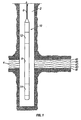
- an electromagnetic induction well logging instrument 10 is shown disposed in a wellbore 2 drilled through earth formations.
- the earth formations are shown generally at 4.
- the instrument 10 can be lowered into and withdrawn from the wellbore 2 by means of an armored electrical cable 6 or similar conveyance known in the art.
- the instrument 10 can be assembled from three subsections: an auxiliary electronics unit 14 disposed at one end of the instrument 10; a coil mandrel unit 8 attached to the auxiliary electronics unit 14; and a receiver/signal processing/telemetry electronics unit 12 attached to the other end of the coil mandrel unit 8, this unit 12 typically being attached to the cable 6.
- the coil mandrel unit 8 includes induction transmitter and receiver coils, as will be further explained, for inducing electromagnetic fields in the earth formations 4 and for receiving voltage signals induced by eddy currents flowing in the earth formations 4 as a result of the electromagnetic fields induced therein.
- the auxiliary electronics unit 14 can include a signal generator and power amplifiers (not shown) to cause alternating currents of selected frequencies to flow through transmitter coils in the coil mandrel unit 8.
- the receiver/signal processing/telemetry electronics unit 12 can include receiver circuits (not shown) for detecting voltages induced in receiver coils in the coil mandrel unit 8, and circuits for processing these received voltages (not shown) into signals representative of the conductivities of various layers, shown as 4A through 4F of the earth formations 4.
- the receiver/signal processing/telemetry electronics unit 12 can include signal telemetry to transmit the conductivity- related signals to the earth's surface along the cable 6 for further processing, or alternatively can store the conductivity related signals in an appropriate recording device (not shown) for processing after the instrument 10 is withdrawn from the wellbore 2.
- Fig. 2 the configuration of transmitter and receiver coils in a preferred embodiment of the 3DExplorer TM induction logging instrument of Baker Hughes is disclosed.
- Three orthogonal transmitters 101,103 and 105 that are referred to as the T x , T z , and T y transmitters are shown (the z - axis is the longitudinal axis of the tool).
- Corresponding to the transmitters 101,103 and 105 are associated receivers 107,109 and 111, referred to as the R x , R z , and R y receivers, for measuring the corresponding magnetic fields H xx , H zz , and H yy .
- the receivers 113 and 115 measure two cross-components H xy , and H xz of the magnetic field produced by the x - component transmitter.
- Fig. 3 Shown on the left panel is a resisitivity model with horizontal and vertical resistivities denoted by 201a and 201b.
- the model has three anisotropic intervals 203, 205, 207 where the vertical resisitivity R v is greater than the horizontal resisitivity R h ..
- the right panel in Fig. 3 shows the apparent conductivity responses for the H xx 211 and H zz 215 components. Also shown is the H xx component 213 if the resisitivity model is isotropic.
- the H zz response for an isotropic model is the same as for the anisotropic model.
- the H zz curve is not responsive to anisotropy in the formation.
- the H xx curve is quite complicated and can even reverse sign close to significant resisitivity contrasts. It also may have spikes at bed boundaries.
- the H xx curve is not indicative of the resistive or conductive nature of a bed. Additionally, the H xx response exhibits more skin effect than does the H zz response.
- the first step is obtaining multi-component induction logging data. This may be done by use of the tool described above with reference to Figs. 1 and 2 or by any other suitable instrument. These measurements are inverted using a whole space inversion 303.
- the synthetic tool response in an isotropic 1 - ⁇ -m whole-space model i.e., without horizontal or vertical boundaries
- the synthetic whole-space response is then compared with measured field data at each logging depth and the horizontal and vertical resistivities ( R h and R v ) are adjusted to match the synthetic responses with the measured field responses.
- the borehole inclination (relative to the layers) and the azimuth are required input parameters.
- the borehole inclination and azimuth may be obtained using a method such as is taught by U.S. Patent 5,999,883 to Gupta et al .
- the model response depends nonlinearly upon a model parameter vector m comprising a plurality of layers each having an associated value of R h and R v .
- m 1 m 2 m 2 m 4 ⁇ m 2 ⁇ n - 1 m 2 ⁇ n [ R h ⁇ 1 R v ⁇ 1 R h ⁇ 2 R v ⁇ 2 ⁇ R vn R hn ] where n is the number of layers in the model.
- J is the Jacobian or sensitivity matrix of partial derivatives of changes in the data to small changes in the parameter.
- the difference between the measured and the synthetic data is )d
- ⁇ is a regularization parameter
- I is the identity matrix.
- Eq. (4) is solved using a Singular Value Decomposition as taught by Lanczos although any other method may be used.
- the inversion process is extremely fast because it only involves analytical solutions of the anisotropic response as represented by eq. (2).
- the obtained multi-component log data are also input to a bed boundary detection step 305.
- United States Patent 5,999,884 to Kriegshauser et al . having the same assignee as the present application teaches a method for estimating axial positions of formation layer boundaries from transverse electromagnetic induction signals.
- a first derivative is calculated with respect to depth of the induction signals.
- a second derivative of the signals is calculated.
- the second derivative is muted.
- Layer boundaries are selected at axial positions where the muted second derivative is non zero, and the first derivative changes sign.
- the selected boundaries are thickness filtered to eliminate boundaries which have the same axial spacing as the spacing between an induction transmitter and receiver used to measure the induction signals, and to eliminate boundaries having a spacing less than an axial resolution of the induction signals.
- the process is repeated using transverse induction measurements made at another frequency. Layer boundaries that are common to the two frequency determinations are determined to be the layer boundaries.
- Kriegshauser discloses a frequency domain method for bed boundary determination.
- the induction signals are transformed into the spatial frequency domain, and low pass filtered at a band limit about equal to the axial resolution of the induction signals.
- the central first derivative of the filtered signals is calculated and the central first derivative inverse-transformed back to the spatial domain. Zero crossings of the inverse-transformed first derivative are indicative of formation boundaries.
- the output of the inversion 303 and the output of the bed boundary detection 305 are combined to give an initial 1-D layered model of the earth.
- This initial model comprises the layers from 305 and associated horizontal and vertical resistivities from 303. From the initial model, the shoulder bed corrections are calculated and applied to the measurements 309.
- the test for acceptability is that the whole space response of the layered model at the middle of each layer should be within some predetermined threshold of the measurements shoulder bed corrected measurements. Alternatively, the iterative procedure is carried out for a specified number of iterations. If the model is not acceptable, the process iteratively goes back to 309 and steps 309 - 313 are repeated until either the model is acceptable or the iterative process has been carried out a predetermined number of times. If the model is acceptable, the process terminates 317 and the model may be used for subsequent petrophysical processing and interpretation. For example, water saturation may be determined for the layers in the inverted model from a knowledge of the resistivities of the layers.
- the present invention has been discussed above with respect to measurements made by a transverse induction logging tool conveyed on a wireline. This is not intended to be a limitation and the method is equally applicable to measurements made using a comparable tool conveyed on a measurement-while-drilling (MWD) assembly or on coiled tubing.
- MWD measurement-while-drilling
Landscapes
- Physics & Mathematics (AREA)
- Engineering & Computer Science (AREA)
- Remote Sensing (AREA)
- Life Sciences & Earth Sciences (AREA)
- Electromagnetism (AREA)
- Environmental & Geological Engineering (AREA)
- Geology (AREA)
- General Life Sciences & Earth Sciences (AREA)
- General Physics & Mathematics (AREA)
- Geophysics (AREA)
- Geophysics And Detection Of Objects (AREA)
Claims (11)
- Procédé de détermination d'un paramètre auquel on s'intéresse de formations souterraines contenant du sable et du schiste entourant un sondage, le procédé comprenant :(a) le transport d'un outil de diagraphie électromagnétique dans le sondage et l'utilisation d'au moins un émetteur électromagnétique et un récepteur électromagnétique sur l'outil pour obtenir des mesures portant sur une résistivité horizontale et une résistivité verticale de la formation ;(b) l'obtention de plusieurs intervalles de couche pour le sous-sol à partir des mesures obtenues ;(c) la dérivation d'une résistivité horizontale et d'une résistivité verticale à plusieurs profondeurs à partir desdites mesures en utilisant un modèle d'espace entier anisotrope ;(d) l'obtention, à partir des résistivités horizontale et verticale dérivées, d'un modèle 1D de couches ;(e) la dérivation de corrections de strates de rebord basées sur le modèle de couches 1D et le modèle d'espace entier ;(f) l'application des corrections de strates de rebord auxdites mesures pour obtenir des mesures corrigées au niveau des strates de rebord ;(g) la détermination d'une différence entre lesdites mesures corrigées au niveau des strates de rebord au centre de chacune desdites multiples couches et une réponse synthétique du modèle d'espace entier auxdits centres ; et(h) la répétition itératives des étapes (c) à (g) pour donner un modèle de couches 1D mis à jour ;(i) l'utilisation du modèle de couche 1D mis à jour pour un traitement pétrophysique et une interprétation.
- Procédé selon la revendication 1, dans lequel ledit outil de diagraphie électromagnétique est transporté sur l'un de (i) un câble, (ii) une garniture de forage et (iii) une colonne enroulée.
- Procédé selon la revendication 1, dans lequel le paramètre auquel on s'intéresse est au moins l'un de (i) une résistivité horizontale de l'une desdites couches, (ii) une résistivité verticale de l'une desdites couches, (iii) une saturation en fluide de l'une desdites couches.
- Procédé selon la revendication 1, dans lequel la dérivation de ladite résistivité horizontale et de ladite résistivité verticale auxdites plusieurs profondeurs comprend en outre l'exécution d'une inversion d'espace entier.
- Procédé selon la revendication 4, dans lequel l'exécution d'une inversion d'espace entier comprend en outre le calcul d'une réponse d'outil synthétique.
- Procédé selon la revendication 4, dans lequel l'exécution d'une inversion d'espace entier comprend en outre une mise à jour d'estimations desdites résistivités horizontale et verticale en utilisant une procédure Lanczos.
- Procédé selon la revendication 1, dans lequel l'obtention desdits multiples intervalles de couches comprend en outre la détermination de dérivées première et seconde par rapport à la profondeur desdites mesures.
- Procédé selon la revendication 1, dans lequel l'obtention desdits plusieurs intervalles de couches comprend en outre :(i) le fait de soumettre à une transformation de Fourier lesdits signaux dans le domaine de fréquence spatiale ;(ii) le filtrage passe-bas desdits signaux ayant subi une transformation de Fourier à une coupure approximativement égale à une résolution axiale desdits signaux d'induction ;(iii) de calcul d'une dérivée première centrale desdits signaux à transformation de Fourier, filtrés ;(iv) le calcul d'une transformée de Fourier inverse de ladite dérivée première centrale ;(v) la sélection de racines de ladite dérivée première centrale à transformation de Fourier inverse ; et(vi) le test de propriétés localisées de ladite dérivée première centrale à transformation de Fourier inverse dans un nombre sélectionné de points d'échantillon de données desdites racines, procurant ainsi des indications de limites de couches de la formation dans des positions axiales comme étant le plus probablement vraies pour lesdites limites de couches de la formation.
- Procédé selon la revendication 1, dans lequel la dérivée de corrections de strates de rebord comprend en outre :(i) la détermination d'une réponse synthétique de couches en une dimension calculée à partir du modèle de couche en utilisant une réponse d'outil synthétique ;(ii) la détermination d'une réponse d'espace entier en utilisant lesdites résistivités horizontale et verticale ; et(iii) l'obtention de ladite correction de strates de rebord en tant que différence entre ladite réponse synthétique de couches 1-D et ladite réponse d'espace entier.
- Procédé selon la revendication 1, dans lequel l'étape (h) est exécutée jusqu'à ce que ladite différence soit inférieure à un seuil prédéterminé.
- Procédé selon la revendication 1, dans lequel l'étape (h) est exécutée sur un nombre préalablement spécifié d'itérations.
Applications Claiming Priority (3)
| Application Number | Priority Date | Filing Date | Title |
|---|---|---|---|
| US09/676,097 US6466872B1 (en) | 1999-11-08 | 2000-09-29 | Method for determination of apparent resistivities of anisotropic reservoirs |
| US676097 | 2000-09-29 | ||
| PCT/US2001/030106 WO2002027357A1 (fr) | 2000-09-29 | 2001-09-20 | Procede servant a determiner les resistivites apparentes de reservoirs anisotropes |
Publications (3)
| Publication Number | Publication Date |
|---|---|
| EP1328832A1 EP1328832A1 (fr) | 2003-07-23 |
| EP1328832A4 EP1328832A4 (fr) | 2005-04-27 |
| EP1328832B1 true EP1328832B1 (fr) | 2009-01-14 |
Family
ID=24713209
Family Applications (1)
| Application Number | Title | Priority Date | Filing Date |
|---|---|---|---|
| EP01973547A Expired - Lifetime EP1328832B1 (fr) | 2000-09-29 | 2001-09-20 | Procede servant a determiner les resistivites apparentes de reservoirs anisotropes |
Country Status (5)
| Country | Link |
|---|---|
| US (2) | US6466872B1 (fr) |
| EP (1) | EP1328832B1 (fr) |
| CA (1) | CA2423927A1 (fr) |
| NO (1) | NO20031426L (fr) |
| WO (1) | WO2002027357A1 (fr) |
Families Citing this family (43)
| Publication number | Priority date | Publication date | Assignee | Title |
|---|---|---|---|---|
| US6636045B2 (en) * | 2001-04-03 | 2003-10-21 | Baker Hughes Incorporated | Method of determining formation anisotropy in deviated wells using separation of induction mode |
| AU2002330989A1 (en) * | 2001-08-03 | 2003-04-01 | Baker Hughes Incorporated | A method and apparatus for a multi-component induction instrumentmeasuring system |
| US6819112B2 (en) * | 2002-02-05 | 2004-11-16 | Halliburton Energy Services, Inc. | Method of combining vertical and magnetic dipole induction logs for reduced shoulder and borehole effects |
| US7463035B2 (en) * | 2002-03-04 | 2008-12-09 | Baker Hughes Incorporated | Method and apparatus for the use of multicomponent induction tool for geosteering and formation resistivity data interpretation in horizontal wells |
| US6611762B1 (en) * | 2002-04-04 | 2003-08-26 | Halliburton Energy Services, Inc. | Method for determining parameters of earth formations surrounding a well bore |
| US6998844B2 (en) * | 2002-04-19 | 2006-02-14 | Schlumberger Technology Corporation | Propagation based electromagnetic measurement of anisotropy using transverse or tilted magnetic dipoles |
| GB2409526B (en) * | 2002-07-10 | 2005-11-30 | Exxonmobil Upstream Res Co | Apparatus and method for measurement of the magnetic induction tensor using triaxial induction arrays |
| US6950748B2 (en) * | 2002-08-19 | 2005-09-27 | Schlumberger Technology Corporation | Methods and systems for resistivity anisotropy formation analysis |
| US6906521B2 (en) * | 2002-11-15 | 2005-06-14 | Baker Hughes Incorporated | Multi-frequency focusing for MWD resistivity tools |
| US7027922B2 (en) * | 2003-08-25 | 2006-04-11 | Baker Hughes Incorporated | Deep resistivity transient method for MWD applications using asymptotic filtering |
| US7091877B2 (en) * | 2003-10-27 | 2006-08-15 | Schlumberger Technology Corporation | Apparatus and methods for determining isotropic and anisotropic formation resistivity in the presence of invasion |
| US7027923B2 (en) * | 2003-12-12 | 2006-04-11 | Schlumberger Technology Corporation | Method for determining sonde error for an induction or propagation tool with transverse or triaxial arrays |
| US7359844B2 (en) * | 2004-01-20 | 2008-04-15 | Saudi Arabian Oil Company | Real time earth model for collaborative geosteering |
| US7080699B2 (en) * | 2004-01-29 | 2006-07-25 | Schlumberger Technology Corporation | Wellbore communication system |
| US7386430B2 (en) * | 2004-03-19 | 2008-06-10 | Schlumberger Technology Corporation | Method of correcting triaxial induction arrays for borehole effect |
| US7359800B2 (en) | 2004-05-11 | 2008-04-15 | Baker Hughes Incorporated | Determination of fracture orientation and length using multi-component and multi-array induction data |
| US7274991B2 (en) * | 2004-06-15 | 2007-09-25 | Baker Hughes Incorporated | Geosteering in anisotropic formations using multicomponent induction measurements |
| US8060310B2 (en) * | 2004-06-15 | 2011-11-15 | Baker Hughes Incorporated | Geosteering in earth formations using multicomponent induction measurements |
| US7269515B2 (en) * | 2004-06-15 | 2007-09-11 | Baker Hughes Incorporated | Geosteering in anisotropic formations using multicomponent induction measurements |
| US7317991B2 (en) * | 2005-01-18 | 2008-01-08 | Baker Hughes Incorporated | Multicomponent induction measurements in cross-bedded and weak anisotropy approximation |
| US7313479B2 (en) * | 2005-01-31 | 2007-12-25 | Baker Hughes Incorporated | Method for real-time well-site interpretation of array resistivity log data in vertical and deviated wells |
| US7599825B2 (en) * | 2005-04-18 | 2009-10-06 | Schlumberger Technology Corporation | Shoulder bed effects removal |
| US7536261B2 (en) * | 2005-04-22 | 2009-05-19 | Schlumberger Technology Corporation | Anti-symmetrized electromagnetic measurements |
| CN101194262B (zh) * | 2005-06-09 | 2012-03-21 | 埃克森美孚上游研究公司 | 在海洋电磁勘测中判断地球垂直电各向异性的方法 |
| KR100837910B1 (ko) * | 2006-12-05 | 2008-06-13 | 현대자동차주식회사 | 액티브 헤드 레스트의 높이 유지 장치 |
| US8330463B2 (en) * | 2007-10-09 | 2012-12-11 | Baker Hughes Incorporated | Protection of a multidirectional antenna |
| AU2009244627A1 (en) * | 2008-04-17 | 2009-11-12 | Richard H. Hardman | Methods for producing a log of material properties |
| US8004282B2 (en) * | 2008-12-01 | 2011-08-23 | Baker Hughes Incorporated | Method of measuring and imaging RXO (near wellbore resistivity) using transient EM |
| US8487625B2 (en) * | 2009-04-07 | 2013-07-16 | Baker Hughes Incorporated | Performing downhole measurement using tuned transmitters and untuned receivers |
| BR112015005594A2 (pt) | 2012-09-12 | 2017-07-04 | Halliburton Energy Services Inc | sistema para determinação de tempo real de anisotropia, inclinação e orientação da formação com dados de mci |
| US9341734B2 (en) * | 2013-03-05 | 2016-05-17 | Ce Liu | Apparatus and method for bed boundary detection |
| CN104422955B (zh) * | 2013-08-22 | 2017-06-20 | 中国石油化工股份有限公司 | 一种利用旅行时变化量进行各向异性参数提取的方法 |
| US10365395B2 (en) | 2014-03-11 | 2019-07-30 | Halliburton Energy Services, Inc. | Multi-component induction logging systems and methods using blended-model inversion |
| US10295698B2 (en) | 2014-04-03 | 2019-05-21 | Halliburton Energy Services, Inc. | Multi-component induction logging systems and methods using selected frequency inversion |
| WO2016209265A1 (fr) * | 2015-06-26 | 2016-12-29 | Landmark Graphics Corporation | Identification de limites de couche de formation sur des mesures de diagraphie de puits |
| US9874094B2 (en) | 2014-07-25 | 2018-01-23 | Landmark Graphics Corporation | Identifying formation layer boundaries on well log measurements |
| US11280929B2 (en) * | 2016-09-19 | 2022-03-22 | Halliburton Energy Services, Inc. | Method of detecting substance saturation in a formation |
| US10301935B2 (en) | 2016-10-18 | 2019-05-28 | Halliburton Energy Services, Inc. | MCI logging for processing downhole measurements |
| CN107132588B (zh) * | 2017-05-05 | 2019-09-24 | 中国石油集团川庆钻探工程有限公司 | 利用测井曲线对构造进行精细校正的方法 |
| US10684386B2 (en) | 2017-08-07 | 2020-06-16 | Baker Hughes, A Ge Company, Llc | Method and apparatus of near-bit resistivity for looking-ahead |
| CN109424358B (zh) * | 2017-08-24 | 2021-08-24 | 中国石油化工股份有限公司 | 大功率随钻电阻率信号发射装置 |
| US11480706B2 (en) | 2017-10-30 | 2022-10-25 | Baker Hughes Holdings Llc | Multiple casing inspection tool combination with 3D arrays and adaptive dual operational modes |
| CN111305834B (zh) * | 2020-02-25 | 2022-09-23 | 北京工业大学 | 基于多探测模式电阻率测井的三维反演初始模型构建方法 |
Family Cites Families (9)
| Publication number | Priority date | Publication date | Assignee | Title |
|---|---|---|---|---|
| US5230386A (en) * | 1991-06-14 | 1993-07-27 | Baker Hughes Incorporated | Method for drilling directional wells |
| US5446654A (en) | 1992-07-16 | 1995-08-29 | Halliburton Company | Shoulder effect logging method |
| EP0665958B1 (fr) * | 1993-07-21 | 1999-01-13 | Western Atlas International, Inc. | Procede de determination de la resistivite d'une formation au moyen des mesures combinees obtenues par des instruments de diagraphie inductive et galvanique |
| US5656930A (en) * | 1995-02-06 | 1997-08-12 | Halliburton Company | Method for determining the anisotropic properties of a subterranean formation consisting of a thinly laminated sand/shale sequence using an induction type logging tool |
| GB2301902A (en) * | 1995-06-08 | 1996-12-18 | Baker Hughes Inc | Detecting boundaries between strata while drilling a borehole |
| US5867806A (en) | 1996-03-13 | 1999-02-02 | Halliburton Energy Services, Inc. | System and method for performing inversion on LWD resistivity logs with enhanced resolution |
| US5781436A (en) * | 1996-07-26 | 1998-07-14 | Western Atlas International, Inc. | Method and apparatus for transverse electromagnetic induction well logging |
| WO1999018454A1 (fr) | 1997-10-08 | 1999-04-15 | Shell Internationale Research Maatschappij B.V. | Procede de correction d'une diagraphie de resistivite |
| US6304086B1 (en) * | 1999-09-07 | 2001-10-16 | Schlumberger Technology Corporation | Method and apparatus for evaluating the resistivity of formations with high dip angles or high-contrast thin layers |
-
2000
- 2000-09-29 US US09/676,097 patent/US6466872B1/en not_active Expired - Lifetime
-
2001
- 2001-09-20 WO PCT/US2001/030106 patent/WO2002027357A1/fr not_active Ceased
- 2001-09-20 CA CA002423927A patent/CA2423927A1/fr not_active Abandoned
- 2001-09-20 EP EP01973547A patent/EP1328832B1/fr not_active Expired - Lifetime
-
2002
- 2002-09-17 US US10/244,960 patent/US6553314B2/en not_active Expired - Fee Related
-
2003
- 2003-03-27 NO NO20031426A patent/NO20031426L/no not_active Application Discontinuation
Also Published As
| Publication number | Publication date |
|---|---|
| US6466872B1 (en) | 2002-10-15 |
| EP1328832A4 (fr) | 2005-04-27 |
| NO20031426L (no) | 2003-05-21 |
| NO20031426D0 (no) | 2003-03-27 |
| CA2423927A1 (fr) | 2002-04-04 |
| US6553314B2 (en) | 2003-04-22 |
| WO2002027357A1 (fr) | 2002-04-04 |
| US20030018434A1 (en) | 2003-01-23 |
| EP1328832A1 (fr) | 2003-07-23 |
Similar Documents
| Publication | Publication Date | Title |
|---|---|---|
| EP1328832B1 (fr) | Procede servant a determiner les resistivites apparentes de reservoirs anisotropes | |
| US6502036B2 (en) | 2-D inversion of multi-component induction logging data to resolve anisotropic resistivity structure | |
| EP2515146B1 (fr) | Procédé et appareil pour l'utilisation d'un outil d'induction multicomposant destiné au géoguidage | |
| US6574562B2 (en) | Determination of formation anisotropy using multi-frequency processing of induction measurements with transverse induction coils | |
| US6636045B2 (en) | Method of determining formation anisotropy in deviated wells using separation of induction mode | |
| US8112227B2 (en) | Processing of multi-component induction measurements in a biaxially anisotropic formation | |
| US20030105590A1 (en) | Water saturation and sand fraction determination from borehole resistivity imaging tool, transverse induction logging and a tensorial water saturation model | |
| EP2026105A2 (fr) | Détermination de la saturation en eau et d'une fraction de sable à partir d'un outil d'imagerie de la résistivité des puits de forage, d'une diagraphie par induction transversale et d'un modèle tensoriel de saturation en eau | |
| US20040117120A1 (en) | Method for resistivity anisotropy determination in conductive borehole environments | |
| US20040133351A1 (en) | Method for resistivity anisotropy determination in near vertical wells | |
| US6381542B1 (en) | Generic, accurate, and real time borehole correction for resistivity tools | |
| US6618676B2 (en) | Efficient and accurate pseudo 2-D inversion scheme for multicomponent induction log data | |
| US7392137B2 (en) | Determination of formation anistrophy, dip and azimuth | |
| US7043370B2 (en) | Real time processing of multicomponent induction tool data in highly deviated and horizontal wells | |
| US6591194B1 (en) | Vertical 1-D inversion with thin layers of equal thickness | |
| EP1483602B1 (fr) | Utilisation d'un outil d'induction mutlicomposant destine au geoguidage et l'interpretation de donnees de resistivite de formation dans des puits horizontaux | |
| US20050122116A1 (en) | Method and apparatus for use of the real component of a magnetic field of multicomponent resistivity measurements |
Legal Events
| Date | Code | Title | Description |
|---|---|---|---|
| PUAI | Public reference made under article 153(3) epc to a published international application that has entered the european phase |
Free format text: ORIGINAL CODE: 0009012 |
|
| 17P | Request for examination filed |
Effective date: 20030416 |
|
| AK | Designated contracting states |
Designated state(s): FR GB |
|
| A4 | Supplementary search report drawn up and despatched |
Effective date: 20050310 |
|
| RIC1 | Information provided on ipc code assigned before grant |
Ipc: 7G 01V 3/28 A |
|
| RA4 | Supplementary search report drawn up and despatched (corrected) |
Effective date: 20050513 |
|
| RAP1 | Party data changed (applicant data changed or rights of an application transferred) |
Owner name: BAKER HUGHES INCORPORATED |
|
| GRAP | Despatch of communication of intention to grant a patent |
Free format text: ORIGINAL CODE: EPIDOSNIGR1 |
|
| RIN1 | Information on inventor provided before grant (corrected) |
Inventor name: GUPTA, PRAVIN Inventor name: FANINI, OTTO, N. Inventor name: YU, LIMING Inventor name: KRIEGSHAUSER, BERTHOLD, F. |
|
| GRAS | Grant fee paid |
Free format text: ORIGINAL CODE: EPIDOSNIGR3 |
|
| GRAA | (expected) grant |
Free format text: ORIGINAL CODE: 0009210 |
|
| AK | Designated contracting states |
Kind code of ref document: B1 Designated state(s): FR GB |
|
| REG | Reference to a national code |
Ref country code: GB Ref legal event code: FG4D |
|
| PLBE | No opposition filed within time limit |
Free format text: ORIGINAL CODE: 0009261 |
|
| STAA | Information on the status of an ep patent application or granted ep patent |
Free format text: STATUS: NO OPPOSITION FILED WITHIN TIME LIMIT |
|
| 26N | No opposition filed |
Effective date: 20091015 |
|
| REG | Reference to a national code |
Ref country code: FR Ref legal event code: ST Effective date: 20110531 |
|
| PG25 | Lapsed in a contracting state [announced via postgrant information from national office to epo] |
Ref country code: FR Free format text: LAPSE BECAUSE OF NON-PAYMENT OF DUE FEES Effective date: 20100930 |
|
| PGFP | Annual fee paid to national office [announced via postgrant information from national office to epo] |
Ref country code: FR Payment date: 20091006 Year of fee payment: 9 |
|
| PGFP | Annual fee paid to national office [announced via postgrant information from national office to epo] |
Ref country code: GB Payment date: 20130918 Year of fee payment: 13 |
|
| GBPC | Gb: european patent ceased through non-payment of renewal fee |
Effective date: 20140920 |
|
| PG25 | Lapsed in a contracting state [announced via postgrant information from national office to epo] |
Ref country code: GB Free format text: LAPSE BECAUSE OF NON-PAYMENT OF DUE FEES Effective date: 20140920 |