EP1329183A2 - Duschkabine mit verbesserter Struktur - Google Patents
Duschkabine mit verbesserter Struktur Download PDFInfo
- Publication number
- EP1329183A2 EP1329183A2 EP03009447A EP03009447A EP1329183A2 EP 1329183 A2 EP1329183 A2 EP 1329183A2 EP 03009447 A EP03009447 A EP 03009447A EP 03009447 A EP03009447 A EP 03009447A EP 1329183 A2 EP1329183 A2 EP 1329183A2
- Authority
- EP
- European Patent Office
- Prior art keywords
- tray
- shower
- side walls
- cabinet
- glass doors
- Prior art date
- Legal status (The legal status is an assumption and is not a legal conclusion. Google has not performed a legal analysis and makes no representation as to the accuracy of the status listed.)
- Withdrawn
Links
Images


Classifications
-
- A—HUMAN NECESSITIES
- A47—FURNITURE; DOMESTIC ARTICLES OR APPLIANCES; COFFEE MILLS; SPICE MILLS; SUCTION CLEANERS IN GENERAL
- A47K—SANITARY EQUIPMENT; ACCESSORIES THEREFOR, e.g. TOILET ACCESSORIES
- A47K3/00—Baths; Showers; Appurtenances therefor
- A47K3/28—Showers or bathing douches
- A47K3/30—Screens or collapsible cabinets for showers or baths
- A47K3/34—Slidable screens
-
- A—HUMAN NECESSITIES
- A47—FURNITURE; DOMESTIC ARTICLES OR APPLIANCES; COFFEE MILLS; SPICE MILLS; SUCTION CLEANERS IN GENERAL
- A47K—SANITARY EQUIPMENT; ACCESSORIES THEREFOR, e.g. TOILET ACCESSORIES
- A47K3/00—Baths; Showers; Appurtenances therefor
- A47K3/28—Showers or bathing douches
- A47K3/40—Pans or trays
-
- A—HUMAN NECESSITIES
- A47—FURNITURE; DOMESTIC ARTICLES OR APPLIANCES; COFFEE MILLS; SPICE MILLS; SUCTION CLEANERS IN GENERAL
- A47K—SANITARY EQUIPMENT; ACCESSORIES THEREFOR, e.g. TOILET ACCESSORIES
- A47K3/00—Baths; Showers; Appurtenances therefor
- A47K3/28—Showers or bathing douches
- A47K3/30—Screens or collapsible cabinets for showers or baths
- A47K2003/305—Sealings between screen and bath- or showertub
Definitions
- This invention refers to a shower, or sauna, cabinet provided with an improved structure.
- cabinets are generally made with elements such as frames or metal structural sections secured to the walls and the base and provided with grooves for housing the glass doors, with suitable sealing material to prevent water from leaking out.
- the walls of the cabinet (generally obtained by thermoforming) thus constitute simple panels for covering and, if necessary, supporting the connecting frames.
- This structure involves relatively high costs and prolonged assembling periods. Moreover, an accumulation of dirt that is difficult to remove inevitably forms in the gaps between the metal sections and the walls, as well as around screws or other means for fastening such metal sections, thereby seriously jeopardizing hygiene.
- the general scope of this invention is to obviate the aforementioned problems by providing a shower cabinet with an improved system for fastening the glass doors to the side walls.
- a shower or sauna cabinet comprising a lower tray, side walls and lateral closing glass doors connected to said walls, characterized in that at least one side chosen between the side walls and the tray comprises, enbloc, seats for housing portions of the edges of the glass doors.
- panelling for a shower cabinet consisting of walls made of plastic material and glass doors, characterized in that it comprises seats in the walls for directly receiving portions of the edge of the glass doors, the seats being formed enbloc in the walls.
- a reduction in the number of components, simplification of the assembling procedure, a reduction in the overall weight and dimensions of the packaging are just a few of the advantages offered by an embodiment according to the invention.
- a shower cabinet generically indicated by reference 10 comprises a shower tray 11 to which are applied fixed glass doors 12 which form the side walls of the cabinet, with a frame 13 comprising vertical uprights 14, 14' and an upper connecting element 15.
- the upper element 15 is design so as to slidingly support movable glass doors 16 with relevant vertical uprights 17, forming the door giving access to the inside of the shower cabinet.
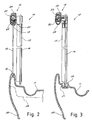
- Fig. 2 which shows a cross-sectional view in correspondence with the fixed glass door 12, with the sliding glass door 16 in the open position, the tray 11 and in the upper connecting element 15 are provided respectively with seats 18, 19 for housing the fixed glass door 12, which can be secured there by means of known airtight means, such as silicone or rubber gaskets.
- the tray 11 As shown in the cross section in Fig. 3, viewed in correspondence with the aperture of the shower cabinet, the tray 11 is also provided with seats 20 for receiving guiding elements 21 for the lower edge of the movable glass door 16.
- the guide elements 21, for example, can be composed of a plurality of grooved blocks, inserted and secured directly in the seats 20.
- the rail 22 can be made of metal to constitute the strengthening element of the frame 13.
- the shower tray and upper element 15 can advantageously be made in any desired shape, comprising the seats and guides for the glass doors, by injection moulding plastic material, with all the benefits offered by the use of such technology.
- the upper element 15 is composed of two half shells 24, 25 which can be coupled extremely easily, for example, by simply fitting them together, after having inserted the metal rail 22 inside them.
- Fig. 4 shows a cross-section viewed in correspondence with one of the uprights 14 of the frame 13.
- the lower tray 11 and the upper element 15 comprise respective seats 26, 27, formed directly in their cross section, to house the ends of the uprights 14.
- the seats are obtained by means of projections protruding from the surface of the tray and the element 15.
- the seats 26, 27 it is possible for the seats 26, 27 to be obtained by means of a recess in the cross section of the aforesaid elements, suitable for receiving complementary protrusions on the uprights.
- Fig. 5 shows the coupling of an end upright 14' with the tray 11 and with the upper element 15 by fitting the upright into the seats 26', 27'.
- appropriate tie rods 38 can be housed inside the uprights to ensure a more efficient anchorage of the uprights to the tray 11 and to the upper connecting element 15.
- the structure of the shower cabinet according to the invention has altogether considerably better stability characteristics as compared to a conventional cabinet provided with a plurality of separate fastening elements to be interposed between the tray and the walls.
- the shower tray 11 can be of relatively limited thickness and its outer surface, as well as the upper element 15, can be easily shaped so as to join together the different cross sections necessary to achieve the above described couplings between the glass doors, uprights and connecting elements.
- the shower cabinet according to the invention can be made with a considerably better aesthetical finish compared to shower cabinets made by means of other technologies.
- the shower tray may be made, as schematically shown by reference 28 in Fig. 2 and as can also be seen in Fig. 6 and Fig. 7, with stiffening undercuts or ribs on its underside.
- the underside of the tray 11 may be advantageously provided during the moulding with seats 39 to house a metal stiffening frame 40.
- the frame 40 can be fastened in the seats 39 in any known way, for example by fixing.
- the shower tray may also comprise, moulded enbloc therewith, a part of the fastening device 29 for fastening a side panel 30 of the tray itself, for the lower finishing of the shower cabinet.
- the fastening device 29 comprises a plate 31 protruding from the lower part of the tray 11 and having a seat or hole 32 for housing a pin 33 protruding sideways from the panel 30 towards the inside of the shower cabinet.
- the pin 33 in the embodiment shown in Fig. 7, is composed of two upper and lower rigid elements 34, 35 capable of supporting the weight of the panel 30 and of two elastic lateral elements 36, 37 capable of snap fitting into the seat 32 in the plate 31.
- the shape and size of the housings of the uprights depend upon the shape and size of the uprights themselves and consequently upon the particular characteristics of the side walls of the cabinet.
- the uprights may be secured to the tray and the upper element for example by glueing or fixing, providing a suitable configuration of the housings each time.
- Fig. 8 shows a shower cabinet generically indicated by reference 110 comprising a lower tray 111, an upper element 112 and side walls 113, to which glass doors 114 are secured.
- the tray 111 and the upper element 112 can be made as previously described for the cabinet 10.
- FIG. 9 shows a portion of a side wall 113, advantageously made by injection moulding plastic material.
- a seat 115 is formed in the latter to house one edge of the fixed glass door 114.
- Said seat consists of a vertical U-shaped groove obtained by moulding the sheet constituting the wall 113 into a suitable shape.
- the groove 115 runs along the entire height of the wall 113 and the lateral edge of the glass door 114 can be inserted within it, advantageously with a slight interference with the walls of the seat to ensure a stable coupling and a sufficient watertight seal.
- the seat 115 is made in correspondence with a curve 116 which forms the front finishing of the wall 113 and offers the possibility of obtaining an interspace 117 for housing known devices (nozzles, pipes, etc.) necessary for operating the shower or sauna.
- the curve 116 also forms the lateral upright, which differs from the example of upright 14' of Fig. 5.
- the lateral panelling formed by the side walls 113 and the glass doors 12 may be shaped differently to that shown, especially as regards the shape and position of the grooves 115, in order to adapt to differemt aesthetical shapes required for the shower cabinet.
- the walls 113 can comprise any accessory normally found in a shower or sauna cabinet, such as for example a shower head 118 or spray nozzles 119, shown schematically in figure 9.
- suitable sealing materials can obviously be applied, for example silicone.
- glass door used here is understood to mean any front closing panel of a shower cabinet, that may not necessarily be made of glass.
Landscapes
- Health & Medical Sciences (AREA)
- Public Health (AREA)
- Epidemiology (AREA)
- General Health & Medical Sciences (AREA)
- Sink And Installation For Waste Water (AREA)
- Residential Or Office Buildings (AREA)
- Manufacturing Of Printed Wiring (AREA)
- Body Structure For Vehicles (AREA)
- Injection Moulding Of Plastics Or The Like (AREA)
Applications Claiming Priority (5)
| Application Number | Priority Date | Filing Date | Title |
|---|---|---|---|
| IT97MI000257 IT237419Y1 (it) | 1997-04-11 | 1997-04-11 | Box doccia con alloggiamento per i cristalli laterali integratonel piatto doccia |
| ITMI970257U | 1997-04-11 | ||
| ITMI970695 IT237936Y1 (it) | 1997-09-30 | 1997-09-30 | Box doccia con sistema perfezionato di fissaggio dei cristalli |
| ITMI970695U | 1997-09-30 | ||
| EP98201147A EP0870460B1 (de) | 1997-04-11 | 1998-04-08 | Duschkabine mit verbesserter Struktur |
Related Parent Applications (1)
| Application Number | Title | Priority Date | Filing Date |
|---|---|---|---|
| EP98201147A Division EP0870460B1 (de) | 1997-04-11 | 1998-04-08 | Duschkabine mit verbesserter Struktur |
Publications (2)
| Publication Number | Publication Date |
|---|---|
| EP1329183A2 true EP1329183A2 (de) | 2003-07-23 |
| EP1329183A3 EP1329183A3 (de) | 2003-11-19 |
Family
ID=26331467
Family Applications (2)
| Application Number | Title | Priority Date | Filing Date |
|---|---|---|---|
| EP03009447A Withdrawn EP1329183A3 (de) | 1997-04-11 | 1998-04-08 | Duschkabine mit verbesserter Struktur |
| EP98201147A Expired - Lifetime EP0870460B1 (de) | 1997-04-11 | 1998-04-08 | Duschkabine mit verbesserter Struktur |
Family Applications After (1)
| Application Number | Title | Priority Date | Filing Date |
|---|---|---|---|
| EP98201147A Expired - Lifetime EP0870460B1 (de) | 1997-04-11 | 1998-04-08 | Duschkabine mit verbesserter Struktur |
Country Status (4)
| Country | Link |
|---|---|
| EP (2) | EP1329183A3 (de) |
| AT (1) | ATE244533T1 (de) |
| DE (1) | DE69816162T2 (de) |
| ES (1) | ES2202735T3 (de) |
Cited By (3)
| Publication number | Priority date | Publication date | Assignee | Title |
|---|---|---|---|---|
| GB2406513A (en) * | 2003-09-10 | 2005-04-06 | Sculptured Homes Llc | Shower system |
| EP1700553A2 (de) | 2005-03-09 | 2006-09-13 | Altura Leiden Holding B.V. | Duschtrennwand |
| US7849531B2 (en) | 2003-09-10 | 2010-12-14 | Sculptured Homes, Llc | Configurable shower system |
Families Citing this family (4)
| Publication number | Priority date | Publication date | Assignee | Title |
|---|---|---|---|---|
| GB2345079B (en) * | 1998-12-11 | 2002-11-27 | Steven Christopher Rule | Window frame construction |
| DE29904936U1 (de) | 1999-03-18 | 1999-07-15 | Reichel, Günter, 35232 Dautphetal | Duschabtrennung |
| ITMI20030489A1 (it) | 2003-03-14 | 2004-09-15 | Giacomo Baiguini | Cabina per doccia autonoma, autoportante con tiranti di accoppiamento. |
| AT526933B1 (de) * | 2023-03-22 | 2024-09-15 | Artweger Gmbh & Co Kg | Badewanne mit Spritzschutzwand |
Family Cites Families (8)
| Publication number | Priority date | Publication date | Assignee | Title |
|---|---|---|---|---|
| DE3737313A1 (de) * | 1987-11-04 | 1989-05-18 | Dreier Werk Gmbh | Duschkabine mit duschwanne mit integrierten aufnahmenuten |
| DE3800443C2 (de) * | 1988-01-09 | 1996-11-07 | Spirella Gmbh | Eckverbindung für die Rahmenkonstruktion einer Dusch- oder Badewannenabtrennung u. dgl. |
| DE3800444C2 (de) * | 1988-01-09 | 1997-01-23 | Spirella Gmbh | Führungsbeschlag zur Aufhängung und Führung einer Schiebetür oder einer Schiebewand bei Dusch- oder Badewannenabtrennungen |
| DE4115337C1 (en) * | 1991-03-28 | 1992-05-14 | Schulte-Duschkabinenbau Gmbh & Co Kg, 5768 Sundern, De | Corner shower cubicle wall with curved entry - has each door element with runner rail, whose suspension track moves in or on wall side suspension element |
| DE59203205D1 (de) * | 1991-09-16 | 1995-09-14 | Romay Ag | Duschkabine. |
| DE9303155U1 (de) * | 1993-03-04 | 1993-04-22 | Koralle Sanitärprodukte GmbH & Co, 4973 Vlotho | Duschkabine |
| DE9305281U1 (de) * | 1993-04-07 | 1993-06-17 | Munch, Paul-Jean, Labaroche | Bausatz für eine Fertigduschkabine |
| IT231975Y1 (it) * | 1993-09-21 | 1999-08-10 | Albatros System Spa | Piatto per doccia, in particolare per box doccia autoportante |
-
1998
- 1998-04-08 EP EP03009447A patent/EP1329183A3/de not_active Withdrawn
- 1998-04-08 ES ES98201147T patent/ES2202735T3/es not_active Expired - Lifetime
- 1998-04-08 EP EP98201147A patent/EP0870460B1/de not_active Expired - Lifetime
- 1998-04-08 DE DE69816162T patent/DE69816162T2/de not_active Expired - Lifetime
- 1998-04-08 AT AT98201147T patent/ATE244533T1/de active
Cited By (5)
| Publication number | Priority date | Publication date | Assignee | Title |
|---|---|---|---|---|
| GB2406513A (en) * | 2003-09-10 | 2005-04-06 | Sculptured Homes Llc | Shower system |
| US7269862B2 (en) | 2003-09-10 | 2007-09-18 | Sculptured Homes, Llc | Configurable shower system |
| GB2406513B (en) * | 2003-09-10 | 2008-01-02 | Sculptured Homes Llc | Configurable shower system |
| US7849531B2 (en) | 2003-09-10 | 2010-12-14 | Sculptured Homes, Llc | Configurable shower system |
| EP1700553A2 (de) | 2005-03-09 | 2006-09-13 | Altura Leiden Holding B.V. | Duschtrennwand |
Also Published As
| Publication number | Publication date |
|---|---|
| EP1329183A3 (de) | 2003-11-19 |
| ATE244533T1 (de) | 2003-07-15 |
| DE69816162T2 (de) | 2004-06-09 |
| EP0870460A2 (de) | 1998-10-14 |
| EP0870460A3 (de) | 1999-05-26 |
| EP0870460B1 (de) | 2003-07-09 |
| ES2202735T3 (es) | 2004-04-01 |
| DE69816162D1 (de) | 2003-08-14 |
Similar Documents
| Publication | Publication Date | Title |
|---|---|---|
| US4396240A (en) | Storage system | |
| US4769862A (en) | Shower curtain support | |
| EP2653813B1 (de) | Regal und Kühlschrank damit | |
| US7410230B2 (en) | Refrigerator with multi-piece mullion having stepped offset | |
| US20050086736A1 (en) | Shower surround structure | |
| CA2051707A1 (en) | Molding of synthetic resin foam with hidden fittings | |
| KR200491563Y1 (ko) | 욕실장 미닫이식 개폐문의 구조 | |
| EP0870460B1 (de) | Duschkabine mit verbesserter Struktur | |
| US5123129A (en) | Waterproof hinged panel assembly | |
| US4095860A (en) | Storage system | |
| KR101756139B1 (ko) | 욕실장용 슬라이딩 도어 | |
| KR102405566B1 (ko) | 슬라이딩도어가 구비된 가구의 상판 휨 방지구조 | |
| CA1292499C (en) | Drawer | |
| CA1217915A (en) | Profiled rail | |
| KR200382764Y1 (ko) | 조립식 화장실의 커버 연결장치 | |
| KR200368928Y1 (ko) | 조립식 화장실의 칸막이 고정장치 | |
| JPS6133811Y2 (de) | ||
| EP1095607B1 (de) | Duschkabine und Dichtungsanordnung | |
| KR200382765Y1 (ko) | 조립식 화장실의 커버 연결장치 | |
| KR200393512Y1 (ko) | 조립식 화장실 도어의 안전보호대 | |
| KR200382763Y1 (ko) | 조립식 화장실의 커버 연결장치 | |
| US3817590A (en) | Means for supporting roller assemblies in a dishwasher tub | |
| JP2005296360A (ja) | ユニットバス | |
| JP3857927B2 (ja) | 間仕切り | |
| KR200382762Y1 (ko) | 조립식 화장실의 커버 연결장치 |
Legal Events
| Date | Code | Title | Description |
|---|---|---|---|
| PUAI | Public reference made under article 153(3) epc to a published international application that has entered the european phase |
Free format text: ORIGINAL CODE: 0009012 |
|
| AC | Divisional application: reference to earlier application |
Ref document number: 0870460 Country of ref document: EP Kind code of ref document: P |
|
| AK | Designated contracting states |
Designated state(s): AT DE ES FR GB IT NL |
|
| PUAL | Search report despatched |
Free format text: ORIGINAL CODE: 0009013 |
|
| AK | Designated contracting states |
Kind code of ref document: A3 Designated state(s): AT DE ES FR GB IT NL |
|
| RIC1 | Information provided on ipc code assigned before grant |
Ipc: 7A 47K 3/28 A Ipc: 7A 47K 3/34 B Ipc: 7A 47K 3/40 B |
|
| 17P | Request for examination filed |
Effective date: 20040518 |
|
| AKX | Designation fees paid |
Designated state(s): AT DE ES FR GB IT NL |
|
| 17Q | First examination report despatched |
Effective date: 20060112 |
|
| STAA | Information on the status of an ep patent application or granted ep patent |
Free format text: STATUS: THE APPLICATION IS DEEMED TO BE WITHDRAWN |
|
| 18D | Application deemed to be withdrawn |
Effective date: 20070315 |