EP1329231A1 - Instrument médical pour l'irrigation et/ou l'aspiration - Google Patents
Instrument médical pour l'irrigation et/ou l'aspiration Download PDFInfo
- Publication number
- EP1329231A1 EP1329231A1 EP02001463A EP02001463A EP1329231A1 EP 1329231 A1 EP1329231 A1 EP 1329231A1 EP 02001463 A EP02001463 A EP 02001463A EP 02001463 A EP02001463 A EP 02001463A EP 1329231 A1 EP1329231 A1 EP 1329231A1
- Authority
- EP
- European Patent Office
- Prior art keywords
- ball
- flow channel
- instrument
- instrument according
- actuating member
- Prior art date
- Legal status (The legal status is an assumption and is not a legal conclusion. Google has not performed a legal analysis and makes no representation as to the accuracy of the status listed.)
- Granted
Links
- 238000003973 irrigation Methods 0.000 title description 3
- 230000002262 irrigation Effects 0.000 title description 3
- 238000007789 sealing Methods 0.000 claims abstract description 41
- 239000012530 fluid Substances 0.000 claims description 15
- 238000011144 upstream manufacturing Methods 0.000 claims description 3
- 238000011010 flushing procedure Methods 0.000 description 26
- 230000000694 effects Effects 0.000 description 9
- 239000007788 liquid Substances 0.000 description 5
- 239000000919 ceramic Substances 0.000 description 4
- 238000010276 construction Methods 0.000 description 2
- 230000003287 optical effect Effects 0.000 description 2
- 238000003825 pressing Methods 0.000 description 2
- 238000001356 surgical procedure Methods 0.000 description 2
- 239000008280 blood Substances 0.000 description 1
- 210000004369 blood Anatomy 0.000 description 1
- 229910010293 ceramic material Inorganic materials 0.000 description 1
- 238000004140 cleaning Methods 0.000 description 1
- 230000001627 detrimental effect Effects 0.000 description 1
- 238000010586 diagram Methods 0.000 description 1
- 230000009977 dual effect Effects 0.000 description 1
- 230000002349 favourable effect Effects 0.000 description 1
- 239000012535 impurity Substances 0.000 description 1
- 238000002955 isolation Methods 0.000 description 1
- 238000002324 minimally invasive surgery Methods 0.000 description 1
- 238000010926 purge Methods 0.000 description 1
- 238000005096 rolling process Methods 0.000 description 1
- 235000019592 roughness Nutrition 0.000 description 1
- 239000007787 solid Substances 0.000 description 1
- 238000003860 storage Methods 0.000 description 1
- 210000003813 thumb Anatomy 0.000 description 1
- 231100000732 tissue residue Toxicity 0.000 description 1
Images


Classifications
-
- F—MECHANICAL ENGINEERING; LIGHTING; HEATING; WEAPONS; BLASTING
- F16—ENGINEERING ELEMENTS AND UNITS; GENERAL MEASURES FOR PRODUCING AND MAINTAINING EFFECTIVE FUNCTIONING OF MACHINES OR INSTALLATIONS; THERMAL INSULATION IN GENERAL
- F16K—VALVES; TAPS; COCKS; ACTUATING-FLOATS; DEVICES FOR VENTING OR AERATING
- F16K1/00—Lift valves or globe valves, i.e. cut-off apparatus with closure members having at least a component of their opening and closing motion perpendicular to the closing faces
- F16K1/14—Lift valves or globe valves, i.e. cut-off apparatus with closure members having at least a component of their opening and closing motion perpendicular to the closing faces with ball-shaped valve member
-
- A—HUMAN NECESSITIES
- A61—MEDICAL OR VETERINARY SCIENCE; HYGIENE
- A61M—DEVICES FOR INTRODUCING MEDIA INTO, OR ONTO, THE BODY; DEVICES FOR TRANSDUCING BODY MEDIA OR FOR TAKING MEDIA FROM THE BODY; DEVICES FOR PRODUCING OR ENDING SLEEP OR STUPOR
- A61M1/00—Suction or pumping devices for medical purposes; Devices for carrying-off, for treatment of, or for carrying-over, body-liquids; Drainage systems
- A61M1/71—Suction drainage systems
- A61M1/74—Suction control
- A61M1/741—Suction control with means for varying suction manually
- A61M1/7413—Suction control with means for varying suction manually by changing the cross-section of the line
-
- A—HUMAN NECESSITIES
- A61—MEDICAL OR VETERINARY SCIENCE; HYGIENE
- A61M—DEVICES FOR INTRODUCING MEDIA INTO, OR ONTO, THE BODY; DEVICES FOR TRANSDUCING BODY MEDIA OR FOR TAKING MEDIA FROM THE BODY; DEVICES FOR PRODUCING OR ENDING SLEEP OR STUPOR
- A61M1/00—Suction or pumping devices for medical purposes; Devices for carrying-off, for treatment of, or for carrying-over, body-liquids; Drainage systems
- A61M1/71—Suction drainage systems
- A61M1/77—Suction-irrigation systems
- A61M1/774—Handpieces specially adapted for providing suction as well as irrigation, either simultaneously or independently
-
- A—HUMAN NECESSITIES
- A61—MEDICAL OR VETERINARY SCIENCE; HYGIENE
- A61M—DEVICES FOR INTRODUCING MEDIA INTO, OR ONTO, THE BODY; DEVICES FOR TRANSDUCING BODY MEDIA OR FOR TAKING MEDIA FROM THE BODY; DEVICES FOR PRODUCING OR ENDING SLEEP OR STUPOR
- A61M1/00—Suction or pumping devices for medical purposes; Devices for carrying-off, for treatment of, or for carrying-over, body-liquids; Drainage systems
- A61M1/71—Suction drainage systems
- A61M1/77—Suction-irrigation systems
- A61M1/772—Suction-irrigation systems operating alternately
Definitions
- the invention relates to a medical instrument for rinsing and / or suction, with an instrument body in which at least a flow channel is present for the passage of a fluid, and with at least one obturator for selectively shutting off the at least one flow channel, and with an actuator for actuating the obturator.
- Such a suction and / or irrigation instrument is used in surgery, especially in minimally invasive surgery, used to during surgery, the operating area to rinse with rinsing liquid, and / or liquid, for example the introduced rinsing fluid, blood and tissue remnants to be sucked out of the operating area.
- the aforementioned known instrument is suitable for both Rinse as well as for suction. While the present invention preferred using the example of an instrument for rinsing and suction however, the present invention is not limited thereto, but also includes such instruments, with which either only rinsed or just sucked can.
- instrument body within the meaning of the present Invention generally understood and can the shaft of such an instrument and / or the handle of such Instruments include.
- the well-known instrument for rinsing and aspirating has accordingly its dual function in the instrument body two flow channels on, wherein the one flow channel, the flushing channel and the other Flow channel represents the suction channel.
- the flushing channel and the suction channel are separated from each other.
- the known instrument At the proximal end of the instrument, the known instrument a connection for connecting a suction hose and a connection for connecting a flushing hose.
- the Suction hose and the flushing hose are supplied with a suction and Rinsing source connected, wherein at the suction hose a corresponding Low pressure is applied, from the distal end to the directed to the proximal end of the instrument, and wherein the rinsing tube flushing fluid from proximal to distal passed becomes.
- Suction vacuum and rinsing liquid are included after switching on the suction and flushing source preferably permanently on the instrument.
- a shut-off for optional Shut off or release the respective flow channel provided wherein the obturator via an actuator in the form a slider can be operated by the operator.
- the obturator has a connected to the slider, provided with recesses movable Plate on which on a solid plate in the instrument body is slidably disposed.
- the immovable plate are openings communicating with the at least one flow channel educated.
- the suction flow or the purge flow can be released or the suction channel and / or the flushing channel can be shut off become.
- the movable plate and the immovable plate lie, touching each other, directly on each other, with both plates in the area of each other contacting surfaces formed of a ceramic material are.
- a disadvantage of this known construction is that such ceramic discs are very expensive in the building. Furthermore require such flat superimposed ceramic Slices with high suction or rinsing pressures high clamping forces, to achieve the required sealing effect. Such high clamping forces in turn generate high friction between the movable and the immovable plate, from which high Operating forces in the operation of the actuator result.
- the invention is therefore based on the object, an instrument of the type mentioned in such a way that the above-mentioned disadvantages are avoided, i. that one high sealing effect of the obturator is achieved, and that nevertheless the operating forces for actuating the obturator as possible are low.
- this object is achieved with regard to the beginning mentioned instrument solved in that the at least one Obturator is a ball, in the closed position on a Sealing edge of the flow channel sealingly abuts, so that they the inner cross section the flow channel closes, that the ball between the closed position for closing the flow channel and a release position for releasing the flow channel substantially movable in the direction transverse to the longitudinal direction of the flow channel is, and that the actuator for moving the ball between the closed position and the release position also essentially transversely to the longitudinal direction of the flow channel movable is.
- the instrument according to the invention therefore has a kind of ball valve on.
- the ball has an outer diameter, which is larger than the inner diameter of the at least one River channel, which close the ball in the closed position should.
- the ball is thus circular or ring sector shaped at the sealing edge of the flow channel sealingly, whereby in Difference to the surface ceramic tiles Plates already with a low contact pressure of the ball on the Sealing edge of the flow channel a high sealing effect is achieved.
- the ball disposed upstream of the sealing edge of the flow channel.
- This measure has the advantage that in the event that at least a flow channel is a suction channel, the ball alone due to the Suction pressure or in the case that the at least one flow channel Flushing is, the ball alone by the flushing pressure against the Sealing edge of the flow channel can be pressed.
- Constructively complex Means for pressing the ball to the sealing edge of the Flow channels, such as springs or the like, are at This construction advantageously not required. Furthermore is achieved by this measure that the contact pressure the ball to the sealing edge with increasing suction or rinsing pressure is even increased, resulting in the safe shut off of the Flow channel sets the required locking force by itself.
- the ball is in arranged a recording of the actuator, in which the Ball has a mobility in the longitudinal direction of the flow channel.
- the ball is in the essentially its center rotatably mounted in the receptacle.
- This measure also advantageously contributes to a reduction the operating force of the actuator, because the ball due to this configuration in its movement of the Closed position in the release position and vice versa to the Rolling sealing edge of the river channel can.
- the mobility the ball in the receptacle in the longitudinal direction of the flow channel limited against the flow direction of the fluid.
- the ball is in Direction transverse to the flow channel substantially immobile in the Recording held.
- the ball at least in the Closed position always the for achieving a high sealing effect favorable centered position with respect to the sealing edge the river channel takes.
- the ball is form-elastic.
- Such an embodiment of the ball advantageously contributes an improved sealing effect against the sealing edge of Flow channel, because the ball due to the elasticity of the formula intimately nestle against the sealing edge of the river channel can and surface irregularities or roughnesses of Ball or the sealing edge of the flow channel is not detrimental can affect the sealing effect of the obturator.
- the actuating member in the closed position or the release position of Preloaded ball.
- Such a bias of the actuator has the advantage that at least one of the two operating positions of the ball, i.e. the closed position or the release position automatically is taken by releasing, which is the ease of use improved the instrument of the invention.
- the bias by means of a on the actuator provided spring be accomplished.
- Instruments has the actuator according to another preferred embodiment of a push button to operate the Actuator on.
- the actuating member detachable together with the ball from the instrument body.
- This measure has the advantage that the ball in the case wear and tear, and secondly, that the obturator and the actuator after removal can be easily cleaned from the instrument body.
- the at least one flow channel a Suction channel for sucking off liquids, tissue residues and the like is, can in the area of the obturator impurities accumulate due to the removability of the actuator and the ball are much easier to remove can.
- the instrument according to the invention fulfills also the medical instruments in general high demands on the disinfectability or cleanability of such Instruments.
- a locking mechanism for locking the actuator on the instrument body in the form of a bayonet catch is available.
- This measure is particularly advantageous when in the flow channel a low pressure or a low pressure gradient prevails because by the bias of the ball to the sealing edge is pressed, creating a sufficient sealing effect of the ball is achieved at the sealing edge of the flow channel.
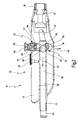
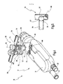
- Figures 1 to 4 is a with the general reference numeral 10th provided medical instrument shown in the Embodiment both for rinsing and for sucking can be used.
- the instrument 10 generally comprises an instrument body 12 on, a handle 14 and one indicated only in Fig. 1 Shaft 16 has.
- the handle 14 is substantially rod-shaped.
- the shaft 16 can with the handle 14th via a receptacle 17 ( Figures 2 and 3) at the distal end of the handle 14 connected and secured by a fixing screw 18 become.
- a flushing port 20th At the proximal end of the handle 14 are a flushing port 20th and a suction port 22 arranged side by side in plan view.
- the longitudinal section according to figures 2 and 3 is passed through the flow channel 28, while the in Figures 2 and 3, not shown Spülkanal of the flow channel 28 separated and parallel to this runs.
- the flow channel 28 (the same applies to the other flow channel for rinsing) extends through the handle 14 therethrough the shaft 16 and continues to pass through the shaft 16 therethrough to its unillustrated distal end. In that Shaft 16, the flow channels can still be separated from each other run, but can also be brought together in the shaft 16 his.
- shut-off device 34 for selectively shutting off and releasing the flow channel 28, the following will be described in more detail.
- the obturator 34 is arranged and divided in the handle 14 of the instrument 10 the flow channel 28 for ease of description in a proximal portion 30 and a distal portion 32nd
- the obturator 34 is via an actuator 35, which also will be described in more detail below, actuated, wherein the obturator 34 between a closed position (FIG. 2) and a release position (Fig. 3) is movable.
- the obturator 34 is formed as a ball 36 and a distal End 38 of the proximal portion 30 of the flow channel 28th arranged adjacent.
- the flow channel 28 has at the distal end 38 of its proximal Section 30 has a sealing edge 40, which is a frontal Edge of the proximal portion 30, and at which the ball 36th 2 sealingly in its closed position according to FIG. 2, so that the ball 36 closes the inner cross section of the flow channel 28.
- a sealing edge 40 which is a frontal Edge of the proximal portion 30, and at which the ball 36th 2 sealingly in its closed position according to FIG. 2, so that the ball 36 closes the inner cross section of the flow channel 28.
- at least the distal end 38 and the Sealing edge 40 formed in cross-section around, so that the ball 36 over a closed circle or a closed Annulus sealingly abuts the sealing edge 40 of the flow channel 28.
- the ball 36 has a diameter correspondingly, which is larger than the inner diameter of the flow channel 28th
- the ball 36 is in the closed position shown in FIG. 2 alone due to the prevailing in the flow channel 28 suction or flow pressure according to an arrow 42 against the sealing edge 40 of the River channel 28 pressed. This is achieved by the ball 36 with respect to the flow direction passing through the flow channel 28 or direction of the pressure gradient of the fluid upstream the sealing edge 40 of the flow channel 28 is arranged.
- This movement of the ball 36 from the closed position in the Release position is activated by means of the actuator 35 accomplished, as well as the reverse movement of the ball 36 of the release position in Fig. 3 in the closed position in FIG. 2.
- the actuator 35 is in the direction transverse to the flow channel 28 movable.
- the actuator 35 is in the form of a slide, having a receptacle 50 for the ball 36.
- the receptacle 50 is shown in FIGS. 2 and 4 in the manner of a cage by holding elements 52 and 54, the ball 36 in the actuating direction front and back or in Fig. 2 to 4 above and below border, and by the actuating direction lateral holding elements 56 and 58 are formed, the ball substantially laterally mounting.
- the ball 36 is in the receptacle 50 in directions which are directed transversely to the flow channel 28, kept immovable.
- Leave in the area of the retaining element 52 the lateral holding elements 56 and 58 and the holding element 52nd an opening 59 for the passage of the fluid freely.
- the ball 36 has in the receptacle 50 of the actuator 35 in the longitudinal direction of the flow channel 28 a mobility, the to the distal end 38 of the proximal portion 30 of the flow channel 28 is limited by the sealing edge 40 and in opposite Direction by a stop 60.
- the ball 36 is rotatably mounted in the receptacle 50, essentially around its center.
- the ball 36 is also form-elastic, so that they are in the closed position shown in FIG. 2 with a particularly high sealing effect clings to the sealing edge 40 of the flow channel 28.
- the actuator 35 further includes a push button 62, via a plunger 63 with the receptacle 50 for moving the Ball 36 is connected.
- the push button 62 can be comfortable with operate the thumb of the hand holding the handle 14.
- the actuator 35 is by means of a spring 64 in the Closed position of the ball 36 biased.
- the spring 64 supports between the push button 62 and one opposite the instrument body 12 immovable fastening part 66 of the actuator 48, wherein the push button 62 together with the Plunger 63 is movable relative to the fastening part 66.
- the actuator 35 with the ball 36 is in the instrument body 12, i. in the present case in the handle 14 in a Opening 68 in the form of a blind hole in the handle 14th added.
- the actuator 35 is together with the Ball 36 from the instrument body 12, i. in the present case from the handle 14, removable, as shown in Fig. 4.
- the ball 36 is further from the actuator 35 decrease, for example, in the case that the ball 36th to be replaced due to wear. To do so the ball 36 from the support members 52, 54, 56 and 58 in Exit direction of an arrow 70.
- a locking mechanism for locking or unlocking the actuating member 35 on the instrument body 12 is a locking mechanism in the form a bayonet closure provided, which has a groove 72 on the instrument body 12 and a corresponding projection 74 on Actuator 35 includes.
- a pivotable about a longitudinal axis 76 lever 78th provided in the locking position shown in FIG. 1 approximately is arranged in the longitudinal direction of the instrument 10 and in the Unlocked position relative to this position by about 90 ° according to Fig. 4 is pivoted.
- This flushing channel is in a corresponding embodiment Shut-off 80 in the form of a ball 82 (Fig. 4) and an actuator 84 assigned.
- the embodiment of the actuator 84 in conjunction with the ball 82 corresponds to the Embodiment of the actuator 48 in conjunction with the Ball 36.
- Fig. 5 is a relation to the previously described embodiment slightly modified embodiment in a schematic diagram shown in which the ball 36 in the Recording 50 of the actuator 35 is not freely rotatably mounted is, but about a kind of tab or lever 90 on the actuator is attached. It is understood that the attachment is releasable to remove the ball 36 from the actuator to can.
- the lever or tab 90 gives the ball 36 a bias towards the sealing edge 40 of the flow channel 28, whereby the ball 36 pressed against these in the closed position becomes. In this way ensures the bias even then a sufficient sealing effect of the ball 36 when the flow pressure, the pressure gradient or the pressure - volume flow - Quotient in the flow channel 28 is low.
Landscapes
- Health & Medical Sciences (AREA)
- Engineering & Computer Science (AREA)
- Heart & Thoracic Surgery (AREA)
- General Engineering & Computer Science (AREA)
- Life Sciences & Earth Sciences (AREA)
- Anesthesiology (AREA)
- Biomedical Technology (AREA)
- Hematology (AREA)
- Vascular Medicine (AREA)
- Animal Behavior & Ethology (AREA)
- General Health & Medical Sciences (AREA)
- Public Health (AREA)
- Veterinary Medicine (AREA)
- Mechanical Engineering (AREA)
- Pulmonology (AREA)
- External Artificial Organs (AREA)
Priority Applications (3)
| Application Number | Priority Date | Filing Date | Title |
|---|---|---|---|
| EP02001463A EP1329231B1 (fr) | 2002-01-21 | 2002-01-21 | Instrument médical pour l'irrigation et/ou l'aspiration |
| DE50200029T DE50200029D1 (de) | 2002-01-21 | 2002-01-21 | Medizinisches Instrument zum Spülen und/oder Saugen |
| US10/348,441 US6991621B2 (en) | 2002-01-21 | 2003-01-21 | Medical instrument for irrigation and/or suction |
Applications Claiming Priority (1)
| Application Number | Priority Date | Filing Date | Title |
|---|---|---|---|
| EP02001463A EP1329231B1 (fr) | 2002-01-21 | 2002-01-21 | Instrument médical pour l'irrigation et/ou l'aspiration |
Publications (2)
| Publication Number | Publication Date |
|---|---|
| EP1329231A1 true EP1329231A1 (fr) | 2003-07-23 |
| EP1329231B1 EP1329231B1 (fr) | 2003-08-20 |
Family
ID=8185321
Family Applications (1)
| Application Number | Title | Priority Date | Filing Date |
|---|---|---|---|
| EP02001463A Expired - Lifetime EP1329231B1 (fr) | 2002-01-21 | 2002-01-21 | Instrument médical pour l'irrigation et/ou l'aspiration |
Country Status (3)
| Country | Link |
|---|---|
| US (1) | US6991621B2 (fr) |
| EP (1) | EP1329231B1 (fr) |
| DE (1) | DE50200029D1 (fr) |
Cited By (3)
| Publication number | Priority date | Publication date | Assignee | Title |
|---|---|---|---|---|
| WO2012069592A1 (fr) * | 2010-11-26 | 2012-05-31 | Universität Bern Verwaltungsdirektion | Système d'aspiration et d'irrigation |
| FR2999262A1 (fr) * | 2012-12-10 | 2014-06-13 | Jean Pierre Rizzo | Robinet-vanne a boule et a tiroir a usages multiples |
| DE202015102615U1 (de) | 2014-05-26 | 2015-06-23 | Spiegelberg GmbH & Co. KG | Medizinische Vorrichtung zum Spülen und Saugen |
Families Citing this family (20)
| Publication number | Priority date | Publication date | Assignee | Title |
|---|---|---|---|---|
| US20080296814A1 (en) | 2002-06-25 | 2008-12-04 | Joseph Franklin | Gas spring with travel control |
| US10941828B2 (en) | 2002-06-25 | 2021-03-09 | Fox Factory, Inc. | Gas spring with travel control |
| US7703585B2 (en) | 2002-06-25 | 2010-04-27 | Fox Factory, Inc. | Integrated and self-contained suspension assembly having an on-the-fly adjustable air spring |
| US8464850B2 (en) * | 2006-11-16 | 2013-06-18 | Fox Factory, Inc. | Gas spring curve control in an adjustable-volume gas-pressurized device |
| US7963509B2 (en) * | 2007-01-31 | 2011-06-21 | Fox Factory, Inc. | Travel control for a gas spring and gas spring having very short travel modes |
| USD536444S1 (en) * | 2004-09-23 | 2007-02-06 | Karl Storz Gmbh & Co. Kg | Handle for a medical instrument |
| USD536784S1 (en) * | 2004-09-23 | 2007-02-13 | Karl Storz Gmbh & Co. Kg | Handle for a medical instrument |
| US7464972B1 (en) * | 2005-04-01 | 2008-12-16 | Niemietz Roger D | Air evacuation attachment for fire hoses |
| USD569508S1 (en) * | 2006-09-20 | 2008-05-20 | Karl Storz Gmbh & Co. Kg | Medical instrument |
| USD637287S1 (en) * | 2009-10-30 | 2011-05-03 | Allergan, Inc. | Combination handheld delivery device and controller unit |
| US8353874B2 (en) * | 2010-02-18 | 2013-01-15 | Covidien Lp | Access apparatus including integral zero-closure valve and check valve |
| US8747111B2 (en) | 2010-04-30 | 2014-06-10 | 3M Innovative Properties Company | Suction handle, suction handle assembly, and oral care systems comprising same |
| USD674479S1 (en) * | 2010-09-29 | 2013-01-15 | Sound Surgical Technologies Llc | Handpiece for use in power assisted lipoplasty |
| BR302012001341S1 (pt) * | 2011-09-20 | 2014-08-19 | Storz Karl Gmbh & Co Kg | Configuração aplicada em instrumento médico |
| CN103203069B (zh) * | 2013-04-03 | 2015-08-19 | 浙江格宜医疗器械有限公司 | 一种手术用冲洗吸引器 |
| CN103932655A (zh) * | 2014-04-21 | 2014-07-23 | 南京大学医学院附属鼓楼医院 | 腹腔镜工作套管双重清洁和防漏气装置 |
| AU2019100169A4 (en) * | 2019-02-15 | 2019-03-28 | Multigate Medical Products Pty Ltd | A Clip |
| CN110464893B (zh) * | 2019-09-12 | 2021-11-30 | 河南省中医院(河南中医药大学第二附属医院) | 急诊内科用快速安全吸痰器 |
| CN113018597A (zh) * | 2021-03-09 | 2021-06-25 | 天琴亼丝微医疗器械技术(苏州)有限公司 | 一种肿胀液注射器 |
| CN117065111A (zh) * | 2023-08-30 | 2023-11-17 | 湖南医科医工科技有限公司 | 一种具有图像显示功能的冲洗吸引装置 |
Citations (5)
| Publication number | Priority date | Publication date | Assignee | Title |
|---|---|---|---|---|
| US1334870A (en) * | 1916-06-30 | 1920-03-23 | Chio Grease Company | Valve |
| GB1346057A (en) * | 1970-05-29 | 1974-02-06 | Atkinson B R | Fluid control valve |
| FR2646771A1 (fr) * | 1989-05-12 | 1990-11-16 | Synthelabo | Bloqueur hydraulique, destine notamment a etre implante dans le corps humain |
| US5030199A (en) * | 1989-12-11 | 1991-07-09 | Medical Engineering Corporation | Female incontinence control device with magnetically operable valve and method |
| US5312373A (en) * | 1991-02-19 | 1994-05-17 | Dexide, Inc. | Surgical endoscopic cannula with positive touch |
Family Cites Families (4)
| Publication number | Priority date | Publication date | Assignee | Title |
|---|---|---|---|---|
| DD132295B1 (de) | 1977-03-30 | 1979-12-27 | Horst Garbuzinski | Operations-laparoskop |
| DE3928949A1 (de) * | 1989-08-31 | 1991-03-14 | Wagner Gmbh J | Membranpumpe |
| DE4320754A1 (de) * | 1993-06-23 | 1995-01-05 | Hoechst Ag | Vorrichtung zum Applizieren von Implantaten |
| DE20011409U1 (de) | 2000-07-04 | 2000-10-05 | Karl Storz GmbH & Co. KG, 78532 Tuttlingen | Medizinisches Instrument zum Spülen und/oder Saugen |
-
2002
- 2002-01-21 EP EP02001463A patent/EP1329231B1/fr not_active Expired - Lifetime
- 2002-01-21 DE DE50200029T patent/DE50200029D1/de not_active Expired - Lifetime
-
2003
- 2003-01-21 US US10/348,441 patent/US6991621B2/en not_active Expired - Fee Related
Patent Citations (5)
| Publication number | Priority date | Publication date | Assignee | Title |
|---|---|---|---|---|
| US1334870A (en) * | 1916-06-30 | 1920-03-23 | Chio Grease Company | Valve |
| GB1346057A (en) * | 1970-05-29 | 1974-02-06 | Atkinson B R | Fluid control valve |
| FR2646771A1 (fr) * | 1989-05-12 | 1990-11-16 | Synthelabo | Bloqueur hydraulique, destine notamment a etre implante dans le corps humain |
| US5030199A (en) * | 1989-12-11 | 1991-07-09 | Medical Engineering Corporation | Female incontinence control device with magnetically operable valve and method |
| US5312373A (en) * | 1991-02-19 | 1994-05-17 | Dexide, Inc. | Surgical endoscopic cannula with positive touch |
Cited By (6)
| Publication number | Priority date | Publication date | Assignee | Title |
|---|---|---|---|---|
| WO2012069592A1 (fr) * | 2010-11-26 | 2012-05-31 | Universität Bern Verwaltungsdirektion | Système d'aspiration et d'irrigation |
| CN103391791A (zh) * | 2010-11-26 | 2013-11-13 | 伯尔尼大学校长 | 抽吸冲洗装置 |
| FR2999262A1 (fr) * | 2012-12-10 | 2014-06-13 | Jean Pierre Rizzo | Robinet-vanne a boule et a tiroir a usages multiples |
| DE202015102615U1 (de) | 2014-05-26 | 2015-06-23 | Spiegelberg GmbH & Co. KG | Medizinische Vorrichtung zum Spülen und Saugen |
| DE102014209998A1 (de) | 2014-05-26 | 2015-11-26 | Spiegelberg GmbH & Co. KG | Medizinische Vorrichtung zum Spülen und Saugen |
| WO2015181041A1 (fr) | 2014-05-26 | 2015-12-03 | Spiegelberg GmbH & Co. KG | Dispositif médical pour le rinçage et l'aspiration |
Also Published As
| Publication number | Publication date |
|---|---|
| US20030139708A1 (en) | 2003-07-24 |
| EP1329231B1 (fr) | 2003-08-20 |
| DE50200029D1 (de) | 2003-10-02 |
| US6991621B2 (en) | 2006-01-31 |
Similar Documents
| Publication | Publication Date | Title |
|---|---|---|
| EP1329231B1 (fr) | Instrument médical pour l'irrigation et/ou l'aspiration | |
| EP3417906B1 (fr) | Vanne à bouton poussoir médical | |
| DE19802145C1 (de) | Medizinisches Schiebeschaftinstrument | |
| DE69419996T2 (de) | Endoskopisches chirurgisches Instrument mit drehbarem inneren Schaft | |
| DE19748369C2 (de) | Chirurgisches Schiebeschaftinstrument | |
| EP1736200B1 (fr) | Soupape à bouton poussoir pour dispositifs médicaux | |
| DE69607170T2 (de) | Chirurgisches dissektionsinstrument mit hochdruckflüssigkeitsstrahl | |
| EP2578171A1 (fr) | Instrument chirurgical | |
| EP2997876A1 (fr) | Valve d'insufflation et de vidange et endoscope comprenant une valve d'insufflation et de vidange | |
| EP1212983B1 (fr) | Instrument chirurgical | |
| DE4120329C2 (de) | Gewebestanze | |
| EP3015082B1 (fr) | Instrument medical demontable | |
| DE69501933T2 (de) | Chirurgischer handgriff versehen mit einer kontrollierten auslassöffnung | |
| DE4236329C2 (de) | Endoskopisches Instrument | |
| EP2431062B1 (fr) | Instrument médical destiné à l'aspiration et au rinçage | |
| DE102016108054A1 (de) | Chirurgisches Instrument | |
| DE102008033366A1 (de) | Medizinische Vorrichtung | |
| DE20011409U1 (de) | Medizinisches Instrument zum Spülen und/oder Saugen | |
| DE60015402T2 (de) | Vorrichtung zum spülen eines vaskulären katheters | |
| EP4313236A1 (fr) | Valve de cathéter pour régulation d'écoulement d'un fluide | |
| DE102009060716B4 (de) | Saug-Spül-Handgriff für ein endoskopisches Instrument | |
| DE102013224217A1 (de) | Handstück zur Durchführung medizinischer Eingriffe | |
| DE10139444B4 (de) | Endoskop mit Optikarettierung | |
| DE20216617U1 (de) | Ventilanordnung | |
| DE102009060714A1 (de) | Saug-Spül-Handgriff für ein endoskopisches Instrument |
Legal Events
| Date | Code | Title | Description |
|---|---|---|---|
| GRAH | Despatch of communication of intention to grant a patent |
Free format text: ORIGINAL CODE: EPIDOS IGRA |
|
| PUAI | Public reference made under article 153(3) epc to a published international application that has entered the european phase |
Free format text: ORIGINAL CODE: 0009012 |
|
| GRAS | Grant fee paid |
Free format text: ORIGINAL CODE: EPIDOSNIGR3 |
|
| GRAA | (expected) grant |
Free format text: ORIGINAL CODE: 0009210 |
|
| 17P | Request for examination filed |
Effective date: 20021023 |
|
| AK | Designated contracting states |
Designated state(s): AT BE CH CY DE DK ES FI FR GB GR IE IT LI LU MC NL PT SE TR |
|
| AX | Request for extension of the european patent |
Extension state: AL LT LV MK RO SI |
|
| AK | Designated contracting states |
Designated state(s): DE FR GB IT |
|
| AX | Request for extension of the european patent |
Extension state: AL LT LV MK RO SI |
|
| REG | Reference to a national code |
Ref country code: GB Ref legal event code: FG4D Free format text: NOT ENGLISH |
|
| REG | Reference to a national code |
Ref country code: IE Ref legal event code: FG4D Free format text: GERMAN |
|
| REF | Corresponds to: |
Ref document number: 50200029 Country of ref document: DE Date of ref document: 20031002 Kind code of ref document: P |
|
| GBT | Gb: translation of ep patent filed (gb section 77(6)(a)/1977) |
Effective date: 20031215 |
|
| LTIE | Lt: invalidation of european patent or patent extension |
Effective date: 20030820 |
|
| REG | Reference to a national code |
Ref country code: IE Ref legal event code: FD4D |
|
| AKX | Designation fees paid |
Designated state(s): DE FR GB IT |
|
| ET | Fr: translation filed | ||
| PLBE | No opposition filed within time limit |
Free format text: ORIGINAL CODE: 0009261 |
|
| STAA | Information on the status of an ep patent application or granted ep patent |
Free format text: STATUS: NO OPPOSITION FILED WITHIN TIME LIMIT |
|
| 26N | No opposition filed |
Effective date: 20040524 |
|
| PGFP | Annual fee paid to national office [announced via postgrant information from national office to epo] |
Ref country code: GB Payment date: 20101230 Year of fee payment: 10 |
|
| PGFP | Annual fee paid to national office [announced via postgrant information from national office to epo] |
Ref country code: IT Payment date: 20101227 Year of fee payment: 10 Ref country code: FR Payment date: 20110216 Year of fee payment: 10 |
|
| GBPC | Gb: european patent ceased through non-payment of renewal fee |
Effective date: 20120121 |
|
| REG | Reference to a national code |
Ref country code: FR Ref legal event code: ST Effective date: 20120928 |
|
| PG25 | Lapsed in a contracting state [announced via postgrant information from national office to epo] |
Ref country code: GB Free format text: LAPSE BECAUSE OF NON-PAYMENT OF DUE FEES Effective date: 20120121 |
|
| PG25 | Lapsed in a contracting state [announced via postgrant information from national office to epo] |
Ref country code: IT Free format text: LAPSE BECAUSE OF NON-PAYMENT OF DUE FEES Effective date: 20120121 |
|
| PG25 | Lapsed in a contracting state [announced via postgrant information from national office to epo] |
Ref country code: FR Free format text: LAPSE BECAUSE OF NON-PAYMENT OF DUE FEES Effective date: 20120131 |
|
| REG | Reference to a national code |
Ref country code: DE Ref legal event code: R082 Ref document number: 50200029 Country of ref document: DE Representative=s name: WITTE, WELLER & PARTNER PATENTANWAELTE MBB, DE Ref country code: DE Ref legal event code: R081 Ref document number: 50200029 Country of ref document: DE Owner name: KARL STORZ SE & CO. KG, DE Free format text: FORMER OWNER: KARL STORZ GMBH & CO. KG, 78532 TUTTLINGEN, DE |
|
| PGFP | Annual fee paid to national office [announced via postgrant information from national office to epo] |
Ref country code: DE Payment date: 20171218 Year of fee payment: 17 |
|
| REG | Reference to a national code |
Ref country code: DE Ref legal event code: R119 Ref document number: 50200029 Country of ref document: DE |
|
| PG25 | Lapsed in a contracting state [announced via postgrant information from national office to epo] |
Ref country code: DE Free format text: LAPSE BECAUSE OF NON-PAYMENT OF DUE FEES Effective date: 20190801 |