EP1329261A1 - Ionenaustauscheranlage - Google Patents
Ionenaustauscheranlage Download PDFInfo
- Publication number
- EP1329261A1 EP1329261A1 EP03075130A EP03075130A EP1329261A1 EP 1329261 A1 EP1329261 A1 EP 1329261A1 EP 03075130 A EP03075130 A EP 03075130A EP 03075130 A EP03075130 A EP 03075130A EP 1329261 A1 EP1329261 A1 EP 1329261A1
- Authority
- EP
- European Patent Office
- Prior art keywords
- compartment
- compartments
- water
- valve
- regeneration
- Prior art date
- Legal status (The legal status is an assumption and is not a legal conclusion. Google has not performed a legal analysis and makes no representation as to the accuracy of the status listed.)
- Withdrawn
Links
- 239000003456 ion exchange resin Substances 0.000 title claims abstract description 19
- 229920003303 ion-exchange polymer Polymers 0.000 title claims abstract description 19
- NWUYHJFMYQTDRP-UHFFFAOYSA-N 1,2-bis(ethenyl)benzene;1-ethenyl-2-ethylbenzene;styrene Chemical compound C=CC1=CC=CC=C1.CCC1=CC=CC=C1C=C.C=CC1=CC=CC=C1C=C NWUYHJFMYQTDRP-UHFFFAOYSA-N 0.000 title claims abstract description 17
- XLYOFNOQVPJJNP-UHFFFAOYSA-N water Substances O XLYOFNOQVPJJNP-UHFFFAOYSA-N 0.000 claims abstract description 50
- 239000011347 resin Substances 0.000 claims abstract description 35
- 229920005989 resin Polymers 0.000 claims abstract description 35
- 238000000746 purification Methods 0.000 claims abstract description 12
- 230000001172 regenerating effect Effects 0.000 claims abstract description 5
- 230000008929 regeneration Effects 0.000 claims description 43
- 238000011069 regeneration method Methods 0.000 claims description 43
- 239000003153 chemical reaction reagent Substances 0.000 claims description 9
- 230000001105 regulatory effect Effects 0.000 claims description 8
- 238000011161 development Methods 0.000 claims description 6
- 230000018109 developmental process Effects 0.000 claims description 6
- 239000008213 purified water Substances 0.000 claims description 5
- 230000033228 biological regulation Effects 0.000 claims description 2
- 238000011017 operating method Methods 0.000 claims description 2
- 238000004519 manufacturing process Methods 0.000 description 18
- 238000005342 ion exchange Methods 0.000 description 10
- 238000000034 method Methods 0.000 description 6
- 239000000243 solution Substances 0.000 description 4
- 125000000129 anionic group Chemical group 0.000 description 3
- 125000002091 cationic group Chemical group 0.000 description 3
- 125000004122 cyclic group Chemical group 0.000 description 3
- 238000005115 demineralization Methods 0.000 description 3
- 230000002328 demineralizing effect Effects 0.000 description 3
- 230000000694 effects Effects 0.000 description 3
- 150000002500 ions Chemical class 0.000 description 3
- 238000006243 chemical reaction Methods 0.000 description 2
- 239000000126 substance Substances 0.000 description 2
- 150000001450 anions Chemical class 0.000 description 1
- 239000007864 aqueous solution Substances 0.000 description 1
- 239000011324 bead Substances 0.000 description 1
- 150000001768 cations Chemical class 0.000 description 1
- 230000007423 decrease Effects 0.000 description 1
- 230000001419 dependent effect Effects 0.000 description 1
- 238000005516 engineering process Methods 0.000 description 1
- 239000012530 fluid Substances 0.000 description 1
- 239000000499 gel Substances 0.000 description 1
- 230000001939 inductive effect Effects 0.000 description 1
- 125000003010 ionic group Chemical group 0.000 description 1
- 238000012423 maintenance Methods 0.000 description 1
- 230000014759 maintenance of location Effects 0.000 description 1
- 239000000178 monomer Substances 0.000 description 1
- 238000006386 neutralization reaction Methods 0.000 description 1
- 230000003204 osmotic effect Effects 0.000 description 1
- 230000001151 other effect Effects 0.000 description 1
- 238000006068 polycondensation reaction Methods 0.000 description 1
- 238000006116 polymerization reaction Methods 0.000 description 1
- 239000006104 solid solution Substances 0.000 description 1
- 239000012453 solvate Substances 0.000 description 1
- 239000002904 solvent Substances 0.000 description 1
- 238000012546 transfer Methods 0.000 description 1
- 238000011144 upstream manufacturing Methods 0.000 description 1
Images

Classifications
-
- B—PERFORMING OPERATIONS; TRANSPORTING
- B01—PHYSICAL OR CHEMICAL PROCESSES OR APPARATUS IN GENERAL
- B01J—CHEMICAL OR PHYSICAL PROCESSES, e.g. CATALYSIS OR COLLOID CHEMISTRY; THEIR RELEVANT APPARATUS
- B01J49/00—Regeneration or reactivation of ion-exchangers; Apparatus therefor
- B01J49/80—Automatic regeneration
- B01J49/85—Controlling or regulating devices therefor
-
- B—PERFORMING OPERATIONS; TRANSPORTING
- B01—PHYSICAL OR CHEMICAL PROCESSES OR APPARATUS IN GENERAL
- B01J—CHEMICAL OR PHYSICAL PROCESSES, e.g. CATALYSIS OR COLLOID CHEMISTRY; THEIR RELEVANT APPARATUS
- B01J49/00—Regeneration or reactivation of ion-exchangers; Apparatus therefor
- B01J49/70—Regeneration or reactivation of ion-exchangers; Apparatus therefor for large scale industrial processes or applications
Definitions
- the present invention relates to an ion exchange resin plant.
- the invention relates to an ion exchange resin plant for the softening or demineralization of water for industrial use.
- Ion exchange resins can be mainly divided into cationic resins if they contain negative ionized groups capable of exchanging cations, and anionic resins if they contain positive ionic groups capable of exchanging anions.
- amphoteric resins i.e. which contain both anionic and cationic groups bound to the same lattice and resins of the selective type containing, for example, chelating or sequestering groups, capable of fixing particular ions.
- Exchanging resins are generally produced in the form of spheroidal beads obtained by the polymerization or polycondensation of monomers in a non-solvent medium.
- exchanging resins immersed in aqueous solutions absorb water, solvate and are transformed into gels which behave like concentrated solid solutions and swell, due to the effect of osmotic pressure.
- a regeneration phase during which the exchanging resins are treated so as to re-establish the characteristics in order to guarantee the necessary parameter values for the ion exchange to take place in the production phase.
- This cyclic functioning generally characterized all exchange processes, those effecting regeneration by equicurrent or countercurrent circulation and those comprising beds consisting of exchanging resins of the compact or fluid type.
- a possible way of avoiding this disadvantage was to provide a storage tank having a sufficient capacity so as to cover at least the regeneration phase.
- the tank is normally oversized to allow for the non-remote probability of having to repeat a regeneration cycle, if this proved to be not perfectly effective.
- the exchanging bed must obviously also be oversized in order to cover, with a greater production, the consumptions of the regeneration phases.
- the concentration on the resin of the attached ion is at its maximum on the first layer and decreases in the subsequent ones.
- the layer being used, in which the exchange takes place becomes more distant from the inlet zone of the bed.
- the production phase must be interrupted, in order to pass to the regeneration, when the layer of resins to be used for the ion exchange has become so thin that it can no longer guarantee the desired characteristics of the water.
- the criterion mainly followed was to produce plants equipped with separate chambers reserved for the regeneration.
- the plants of the known art also involve enormous production and maintenance costs as they use up considerable quantities of resin installed in relation to the minimum expected duration for the regeneration cycle.
- a first objective of the present invention is therefore to produce an ion exchange resin plant suitable for overcoming the above drawbacks of the known art.
- Another objective of the present invention is to provide a plant with a limited encumbrance, having the same production, which is compact and also having, according to the specific necessities, a development substantially in height or substantially in width.
- a further objective of the present invention is to provide a plant which has great running simplicity and reliability, due to the possibility of effecting the regeneration on a relatively limited number of valves.
- the plant according to the present invention advantageously allows the efficiency of the resin exchange to be maximized by adapting the duration of the production phase to the variations in salinity of the water at the inlet.
- the ion exchange resin plant according to the invention comprises a tank divided into two separate compartments, a first compartment and a second compartment, containing the exchanging resins, said first and second compartments being arranged so as to allow the plant to operate in continuous so that when one compartment is effecting water purification, the other compartment is regenerating the exchanging resins.
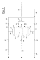
- an ion exchange resin plant in particular for the purification of water, comprises a tank 10 divided into two compartments, a first compartment 11 and a second compartment 12 containing the exchanging resins.
- the first and second compartment 11, 12 are separated from each other by nozzle-holder plates 13, suitable for supporting the exchanging resins arranged on beds of the compact or fluidized type.
- Said nozzle-holder plates 13 also distribute and collect the circulating water.
- Said valve 30 is preferably an automatic regulation valve, driven by a flow-rate signal.
- Each of said first and second compartments 11, 12 is fed with water to be purified, through a feeding line 20 respectively controlled by a first feeding valve 31 for the first compartment 11 and a second feeding valve 31' for the second compartment 12.
- Each of said first and second compartments 11, 12 is also equipped with a reagent line 21 intercepted by a pair of entry valves 33, 33' to regulate the feeding of the regeneration reagent to the first compartment 11 and the second compartment 12, respectively.
- Each of said first and second compartments 11, 12 is also equipped with a discharge line of the regeneration water, the first compartment 11 being equipped with a discharge line 24, whereas the second compartment 12 is equipped with a discharge line 24'.
- Said discharge lines 24 and 24' are intercepted by corresponding discharge valves 32, 32' suitable for regulating the discharge of the regeneration water from the first compartment 11 and the second compartment 12, respectively.
- Said valves 31, 31', and 32, 32' are respectively situated upstream and downstream of the inlet block 25 of the feeding line 20 and outlet block of the discharge lines 24 and 24' into and from each compartment 11, 12 of the tank 10.
- water to be purified coming from the feeding line 20 or the regeneration water coming, each specific time, from the compartment 11 or 12 on which is effecting said regeneration, can alternatively pass through the block 25.
- the plant is consequently capable of instantaneously and continuously producing the required quantity of treated water (demineralized or softened), using a very limited quantity of resin.
- This plant embodiment thus allows the quantity of resins to be dimensioned, referring more to hydraulic rather than physico-chemical parameters, thus optimizing the layer of resin to the minimum value sufficient for guaranteeing the desired chemical characteristics of the water.
- the functioning method of the ion exchange resin plant for the purification of water, or more specifically demineralization or softening of water for industrial use operates using the ion exchange tank 10 subdivided into two compartments filled with the same resin.
- valves 31 and 30 are opened and the desired flow-rate is obtained at the outlet of valve 30.
- compartment 12 effects the regeneration operating as follows:
- compartment 11 By means of an increased feeding from line 20, compartment 11 not only ensures the required water production, but also supplies the water necessary for the regeneration of the compartment 12.
- the compartment 12 remains in standby.
- compartment 12 is activated by opening valve 31' and closing valve 31.
- Valve 30 remains open.
- compartment 12 As soon as compartment 12 starts production, the regeneration of compartment 11 can be activated in exactly the same way as described for compartment 12:
- Compartment 12 not only ensures the required water production, but also supplies the water necessary for the regeneration of compartment 11.
- compartment 11 remains in standby.
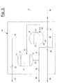
- the tank 10 is divided into the two compartments 11, 12, physically separated by a septum 15, but connected through a duct 16, situated between line 22 and the upper portion of the first compartment 11.
- Two chambers 14 are thus formed, each situated at the top of one compartment 11, 12, advantageously obtaining a regenerating stream from above, in order to make the regeneration operation uniform in the compartments, at the same time however maintaining a substantially vertical development of the plant.
- Said two chambers 14 have the same functions as the single chamber 14, and the functioning of the plant is substantially the same, allowing the regeneration of one compartment effected by withdrawing a part of the treated water, i.e. demineralized or softened, supplied by the other compartment under production thanks to the connection between the two chambers 14 obtained by means of the duct 16.
- Figure 3 shows a second variation of the plant embodiment, which differs from the version of figure 2 in the type of development assigned to the plant.
- This second embodiment variation also has two chambers 14, each of which is situated on top of the corresponding compartment 11 or 12 and has a connecting duct 16 between the two above chambers 14, through which the treated water coming from one of the two compartments under production and sent to the other compartment for regeneration, can flow in both directions.
Landscapes
- Chemical & Material Sciences (AREA)
- Organic Chemistry (AREA)
- Chemical Kinetics & Catalysis (AREA)
- Treatment Of Water By Ion Exchange (AREA)
Applications Claiming Priority (2)
| Application Number | Priority Date | Filing Date | Title |
|---|---|---|---|
| ITMI20020106 | 2002-01-22 | ||
| IT2002MI000106A ITMI20020106A1 (it) | 2002-01-22 | 2002-01-22 | Impianto a resine a scambio ionico |
Publications (1)
| Publication Number | Publication Date |
|---|---|
| EP1329261A1 true EP1329261A1 (de) | 2003-07-23 |
Family
ID=11448947
Family Applications (1)
| Application Number | Title | Priority Date | Filing Date |
|---|---|---|---|
| EP03075130A Withdrawn EP1329261A1 (de) | 2002-01-22 | 2003-01-16 | Ionenaustauscheranlage |
Country Status (3)
| Country | Link |
|---|---|
| US (1) | US6972091B2 (de) |
| EP (1) | EP1329261A1 (de) |
| IT (1) | ITMI20020106A1 (de) |
Families Citing this family (3)
| Publication number | Priority date | Publication date | Assignee | Title |
|---|---|---|---|---|
| US20100193416A1 (en) * | 2009-01-30 | 2010-08-05 | Barbaro Ronald D | Non-biological removal and recovery of nutrients from waste |
| US20180141037A1 (en) * | 2016-11-22 | 2018-05-24 | Csub Auxiliary For Sponsored Programs Administration | Ion exchange column and methods of making and using the same |
| CN110642328A (zh) * | 2019-09-29 | 2020-01-03 | 攀钢集团钛业有限责任公司 | 软化水树脂加入装置及加入方法 |
Citations (5)
| Publication number | Priority date | Publication date | Assignee | Title |
|---|---|---|---|---|
| US4233158A (en) * | 1978-11-01 | 1980-11-11 | Wachsmuth William A | Liquid treatment tank having a volume compensating structure for use with volume variable liquid treatment material |
| JPS6031831A (ja) * | 1983-08-02 | 1985-02-18 | Shinko Fuaudoraa Kk | 向流再生型イオン交換装置 |
| EP0423923A1 (de) * | 1989-10-05 | 1991-04-24 | Culligan International Company | Wasseraufbereitungsvorrichtung |
| WO1994013379A1 (en) * | 1992-12-14 | 1994-06-23 | Ecowater Systems, Inc. | Multi-tank liquid treatment method and apparatus |
| EP1160204A2 (de) * | 2000-05-09 | 2001-12-05 | Harvey Softeners Limited | Wasseraufbereitung |
Family Cites Families (19)
| Publication number | Priority date | Publication date | Assignee | Title |
|---|---|---|---|---|
| US2572848A (en) * | 1950-01-05 | 1951-10-30 | Dorr Co | Method and apparatus for continuously conducting ion exchange operations |
| US2666741A (en) * | 1950-11-09 | 1954-01-19 | Worthington Corp | Regeneration of mixed single bed deionization |
| US2855364A (en) * | 1956-12-14 | 1958-10-07 | Dorr Oliver Inc | Upelow regeneration with porous tube |
| DE1436291C3 (de) * | 1965-10-25 | 1975-12-04 | Degremont Wasseraufbereituns- Gesellschaft Mbh, 4000 Duesseldorf | Rückspülbares Filter für die Filtration von Wasser |
| US3382169A (en) * | 1966-04-04 | 1968-05-07 | Illinois Water Treat Co | Process for deionizing aqueous solutions |
| US3554377A (en) * | 1968-09-18 | 1971-01-12 | Omer E Miller | Liquid treating apparatus |
| US3497069A (en) * | 1968-11-01 | 1970-02-24 | Corning Glass Works | Apparatus for water purification by ion exchange |
| US3617558A (en) * | 1970-11-02 | 1971-11-02 | Illinois Water Treatment Co | Layered ion exchange process |
| US3719591A (en) * | 1971-03-05 | 1973-03-06 | Crane Co | Method for condensate filtration and demineralization |
| GB1386372A (en) * | 1971-04-20 | 1975-03-05 | Steinmueller Gmbh L & C | Process for the continuous treatment of liquids |
| DE2163346A1 (de) * | 1971-12-21 | 1973-06-28 | Steinmueller Gmbh L & C | Verfahren zur kontinuierlichen behandlung von ionenaustauscherpartikeln |
| DE2950875A1 (de) * | 1979-12-18 | 1981-07-02 | Bayer Ag, 5090 Leverkusen | Gegenstromverfahren zur behandlung von fluessigkeiten mit adsorptionsmitteln und vorrichtung zur durchfuehrung das verfahrens |
| DE3040616A1 (de) * | 1980-10-29 | 1982-06-03 | Bayer Ag, 5090 Leverkusen | Gegenstrom-adsorptionsfilter zur behandlung von fluessigkeiten und verfahren zum betreiben des filters |
| FR2502507B1 (fr) * | 1981-03-24 | 1986-08-08 | Degremont Sa | Procede et installation d'echange de masse a contre-courant entre deux phases de densites differentes |
| US4648976A (en) * | 1985-03-07 | 1987-03-10 | Belco Pollution Control Corporation | Integral water demineralizer system and method |
| JPH0659412B2 (ja) * | 1986-12-25 | 1994-08-10 | 株式会社荏原製作所 | イオン交換樹脂の分離移送方法 |
| GB2303802B (en) * | 1994-03-30 | 1997-12-24 | Tingsheng Wang | Process and apparatus for the regeneration of resins in a fixed double-bed type apparatus |
| EP0876198B1 (de) * | 1995-09-14 | 2002-08-21 | Pall Corporation | Verfahren und vorrichtung zum entfernen von eisen aus wässrigen flüssigkeiten |
| US6730229B1 (en) * | 2000-11-10 | 2004-05-04 | Awts, Inc. | Filter screen nozzle and system for fluid processing |
-
2002
- 2002-01-22 IT IT2002MI000106A patent/ITMI20020106A1/it unknown
-
2003
- 2003-01-16 EP EP03075130A patent/EP1329261A1/de not_active Withdrawn
- 2003-01-17 US US10/346,785 patent/US6972091B2/en not_active Expired - Fee Related
Patent Citations (5)
| Publication number | Priority date | Publication date | Assignee | Title |
|---|---|---|---|---|
| US4233158A (en) * | 1978-11-01 | 1980-11-11 | Wachsmuth William A | Liquid treatment tank having a volume compensating structure for use with volume variable liquid treatment material |
| JPS6031831A (ja) * | 1983-08-02 | 1985-02-18 | Shinko Fuaudoraa Kk | 向流再生型イオン交換装置 |
| EP0423923A1 (de) * | 1989-10-05 | 1991-04-24 | Culligan International Company | Wasseraufbereitungsvorrichtung |
| WO1994013379A1 (en) * | 1992-12-14 | 1994-06-23 | Ecowater Systems, Inc. | Multi-tank liquid treatment method and apparatus |
| EP1160204A2 (de) * | 2000-05-09 | 2001-12-05 | Harvey Softeners Limited | Wasseraufbereitung |
Non-Patent Citations (1)
| Title |
|---|
| PATENT ABSTRACTS OF JAPAN vol. 009, no. 153 (C - 288) 27 June 1985 (1985-06-27) * |
Also Published As
| Publication number | Publication date |
|---|---|
| ITMI20020106A1 (it) | 2003-07-22 |
| ITMI20020106A0 (it) | 2002-01-22 |
| US6972091B2 (en) | 2005-12-06 |
| US20030136718A1 (en) | 2003-07-24 |
Similar Documents
| Publication | Publication Date | Title |
|---|---|---|
| US7604725B2 (en) | Water treatment system and method | |
| EP0190739B1 (de) | Wasserentionisierungssystem | |
| MXPA06005386A (es) | Sistema y metodo para tratamiento de a | |
| US3240699A (en) | Upflow regeneration method | |
| US4088563A (en) | Process for the treatment of water solution by ion exchange | |
| US5464530A (en) | Ion exchange methods and systems incorporating regenerant recycling | |
| US4001113A (en) | Ion exchange method | |
| US6972091B2 (en) | Ion exchange resin plant | |
| Abusultan et al. | A hybrid process combining ion exchange resin and bipolar membrane electrodialysis for reverse osmosis remineralization | |
| US3674685A (en) | Process of and apparatus for the ion-exchange treatment of liquids | |
| US6843920B1 (en) | Ion exchange system using U-tube principle | |
| US8152995B2 (en) | Arrangements to reduce hardness of water in a hot water system | |
| US2753302A (en) | Water treating system | |
| US7422691B2 (en) | Method and apparatus for the demineralization of water | |
| US4230807A (en) | Method for regenerating a weak base anion exchanger | |
| CN108793522A (zh) | 一种脱硫废水浓缩减量工艺 | |
| US20040251191A1 (en) | Method of liquid purification using ion exchange resin being kept in a compacted state by means of elastic material | |
| SU1627245A1 (ru) | Способ регенерации катионитовых и анионитовых фильтров в установке дл обессоливани и ум гчени воды | |
| CN108793523A (zh) | 一种脱硫废水浓缩减量装置 | |
| CN117225483B (zh) | 一种组合式阀阵多单元连续离子交换系统 | |
| SU1386579A1 (ru) | Способ регенерации ионита в противоточном фильтре и устройство дл его осуществлени | |
| JPH0346877Y2 (de) | ||
| JPS5931311Y2 (ja) | イオン交換装置 | |
| Prajapati et al. | Water-softening by continuous counter-current ion-exchange single column technique | |
| US6296772B1 (en) | Split ion exchange system and method of operating |
Legal Events
| Date | Code | Title | Description |
|---|---|---|---|
| PUAI | Public reference made under article 153(3) epc to a published international application that has entered the european phase |
Free format text: ORIGINAL CODE: 0009012 |
|
| AK | Designated contracting states |
Designated state(s): AT BE BG CH CY CZ DE DK EE ES FI FR GB GR HU IE IT LI LU MC NL PT SE SI SK TR |
|
| AX | Request for extension of the european patent |
Extension state: AL LT LV MK RO |
|
| 17P | Request for examination filed |
Effective date: 20040114 |
|
| AKX | Designation fees paid |
Designated state(s): AT BE BG CH CY CZ DE DK EE ES FI FR GB GR HU IE IT LI LU MC NL PT SE SI SK TR |
|
| GRAP | Despatch of communication of intention to grant a patent |
Free format text: ORIGINAL CODE: EPIDOSNIGR1 |
|
| STAA | Information on the status of an ep patent application or granted ep patent |
Free format text: STATUS: THE APPLICATION IS DEEMED TO BE WITHDRAWN |
|
| 18D | Application deemed to be withdrawn |
Effective date: 20100819 |