EP1329407A1 - Dispositif pour la distribution d'un ruban adhésif des deux côtés et un rouleau de remplacement pour ce dispositif - Google Patents
Dispositif pour la distribution d'un ruban adhésif des deux côtés et un rouleau de remplacement pour ce dispositif Download PDFInfo
- Publication number
- EP1329407A1 EP1329407A1 EP02388006A EP02388006A EP1329407A1 EP 1329407 A1 EP1329407 A1 EP 1329407A1 EP 02388006 A EP02388006 A EP 02388006A EP 02388006 A EP02388006 A EP 02388006A EP 1329407 A1 EP1329407 A1 EP 1329407A1
- Authority
- EP
- European Patent Office
- Prior art keywords
- carrier strip
- roll
- sided adhesive
- adhesive tape
- pressure base
- Prior art date
- Legal status (The legal status is an assumption and is not a legal conclusion. Google has not performed a legal analysis and makes no representation as to the accuracy of the status listed.)
- Granted
Links
- 239000002390 adhesive tape Substances 0.000 title claims abstract description 32
- 230000002093 peripheral effect Effects 0.000 claims abstract description 25
- 239000000463 material Substances 0.000 claims abstract description 11
- 239000004033 plastic Substances 0.000 claims description 3
- 239000000853 adhesive Substances 0.000 description 13
- 230000001070 adhesive effect Effects 0.000 description 13
- 239000011162 core material Substances 0.000 description 4
- 241001674048 Phthiraptera Species 0.000 description 3
- 230000000694 effects Effects 0.000 description 2
- 239000003292 glue Substances 0.000 description 2
- 238000004806 packaging method and process Methods 0.000 description 2
- 238000000926 separation method Methods 0.000 description 2
- 239000002699 waste material Substances 0.000 description 2
- 239000011111 cardboard Substances 0.000 description 1
- 230000003993 interaction Effects 0.000 description 1
- 239000002991 molded plastic Substances 0.000 description 1
- 239000000123 paper Substances 0.000 description 1
- 239000011087 paperboard Substances 0.000 description 1
- 239000013589 supplement Substances 0.000 description 1
- 239000000725 suspension Substances 0.000 description 1
- 238000004804 winding Methods 0.000 description 1
Images
Classifications
-
- B—PERFORMING OPERATIONS; TRANSPORTING
- B65—CONVEYING; PACKING; STORING; HANDLING THIN OR FILAMENTARY MATERIAL
- B65H—HANDLING THIN OR FILAMENTARY MATERIAL, e.g. SHEETS, WEBS, CABLES
- B65H37/00—Article or web delivery apparatus incorporating devices for performing specified auxiliary operations
- B65H37/002—Web delivery apparatus, the web serving as support for articles, material or another web
- B65H37/005—Hand-held apparatus
-
- B—PERFORMING OPERATIONS; TRANSPORTING
- B65—CONVEYING; PACKING; STORING; HANDLING THIN OR FILAMENTARY MATERIAL
- B65H—HANDLING THIN OR FILAMENTARY MATERIAL, e.g. SHEETS, WEBS, CABLES
- B65H2701/00—Handled material; Storage means
- B65H2701/10—Handled articles or webs
- B65H2701/17—Nature of material
- B65H2701/172—Composite material
- B65H2701/1722—Composite material including layer with adhesive properties
-
- B—PERFORMING OPERATIONS; TRANSPORTING
- B65—CONVEYING; PACKING; STORING; HANDLING THIN OR FILAMENTARY MATERIAL
- B65H—HANDLING THIN OR FILAMENTARY MATERIAL, e.g. SHEETS, WEBS, CABLES
- B65H2701/00—Handled material; Storage means
- B65H2701/10—Handled articles or webs
- B65H2701/17—Nature of material
- B65H2701/172—Composite material
- B65H2701/1726—Composite material including detachable components
-
- B—PERFORMING OPERATIONS; TRANSPORTING
- B65—CONVEYING; PACKING; STORING; HANDLING THIN OR FILAMENTARY MATERIAL
- B65H—HANDLING THIN OR FILAMENTARY MATERIAL, e.g. SHEETS, WEBS, CABLES
- B65H2701/00—Handled material; Storage means
- B65H2701/10—Handled articles or webs
- B65H2701/19—Specific article or web
- B65H2701/194—Web supporting regularly spaced adhesive articles, e.g. labels, rubber articles, labels or stamps
-
- B—PERFORMING OPERATIONS; TRANSPORTING
- B65—CONVEYING; PACKING; STORING; HANDLING THIN OR FILAMENTARY MATERIAL
- B65H—HANDLING THIN OR FILAMENTARY MATERIAL, e.g. SHEETS, WEBS, CABLES
- B65H2701/00—Handled material; Storage means
- B65H2701/30—Handled filamentary material
- B65H2701/37—Tapes
- B65H2701/377—Adhesive tape
- B65H2701/3772—Double-sided
-
- Y—GENERAL TAGGING OF NEW TECHNOLOGICAL DEVELOPMENTS; GENERAL TAGGING OF CROSS-SECTIONAL TECHNOLOGIES SPANNING OVER SEVERAL SECTIONS OF THE IPC; TECHNICAL SUBJECTS COVERED BY FORMER USPC CROSS-REFERENCE ART COLLECTIONS [XRACs] AND DIGESTS
- Y10—TECHNICAL SUBJECTS COVERED BY FORMER USPC
- Y10T—TECHNICAL SUBJECTS COVERED BY FORMER US CLASSIFICATION
- Y10T156/00—Adhesive bonding and miscellaneous chemical manufacture
- Y10T156/12—Surface bonding means and/or assembly means with cutting, punching, piercing, severing or tearing
- Y10T156/1348—Work traversing type
-
- Y—GENERAL TAGGING OF NEW TECHNOLOGICAL DEVELOPMENTS; GENERAL TAGGING OF CROSS-SECTIONAL TECHNOLOGIES SPANNING OVER SEVERAL SECTIONS OF THE IPC; TECHNICAL SUBJECTS COVERED BY FORMER USPC CROSS-REFERENCE ART COLLECTIONS [XRACs] AND DIGESTS
- Y10—TECHNICAL SUBJECTS COVERED BY FORMER USPC
- Y10T—TECHNICAL SUBJECTS COVERED BY FORMER US CLASSIFICATION
- Y10T156/00—Adhesive bonding and miscellaneous chemical manufacture
- Y10T156/17—Surface bonding means and/or assemblymeans with work feeding or handling means
- Y10T156/1788—Work traversing type and/or means applying work to wall or static structure
- Y10T156/1795—Implement carried web supply
-
- Y—GENERAL TAGGING OF NEW TECHNOLOGICAL DEVELOPMENTS; GENERAL TAGGING OF CROSS-SECTIONAL TECHNOLOGIES SPANNING OVER SEVERAL SECTIONS OF THE IPC; TECHNICAL SUBJECTS COVERED BY FORMER USPC CROSS-REFERENCE ART COLLECTIONS [XRACs] AND DIGESTS
- Y10—TECHNICAL SUBJECTS COVERED BY FORMER USPC
- Y10T—TECHNICAL SUBJECTS COVERED BY FORMER US CLASSIFICATION
- Y10T156/00—Adhesive bonding and miscellaneous chemical manufacture
- Y10T156/18—Surface bonding means and/or assembly means with handle or handgrip
Definitions
- the present invention relates to a device for dispensing two sided adhesive tape pieces, comprising a roll of a carrier strip holding pieces of two sided adhesive tape and wound on a hub with an outer radius and provided with a circular cogging, a support for the roll comprising a stub shaft with a direction of axis around which the roll rotates when dispensing tape pieces, a brake pawl for engagement with the circular cogging, a pressure base being in connection with the brake pawl whereby the engagement of the brake pawl with the cogging is released by pressure on the pressure base, a peripheral wall extending along a part of the periphery of the roll, and a path for the carrier strip extending past the pressure base and along a part of the outside of the peripheral wall, the pressure base comprising an outer sliding surface defining a part of the path for the carrier strip with the two sided adhesive tape where the path at the pressure base comprises a portion with a relatively sharp curve with a radius of curvature being essentially smaller than the outer radius of
- the two sided adhesive tape is constituted by a relatively thin, flexible layer on the carrier strip, provided with transverse grooves, the two sided adhesive tape being easily broken when, during use, a piece is applied to a surface desired to be provided with a piece of two sided adhesive tape, e.g. in order to mount a photo or the like.
- the known device is used by pressing the pressure base against said surface with the carrier strip and the two sided adhesive tape being placed between the pressure base and the surface whereupon the device is drawn along the surface.
- US-A-3 839 127 discloses a device for dispensing an adhesive carried by a waste liner from a roll when the device is guided over a surface upon which the adhesive is to be placed. It is also provided with a deflecting member or a 'plough' with an applying edge to separate the waste liner from the adhesive after being placed on a surface.
- US-A-4 704 185 discloses a device for dispensing double sided adhesive tape pieces, labels and the like, where a carrier strip from a roll is guided through a path to an applicator platform with an edge, around this edge and to a mechanism for advancing the carrier strip, the tape pieces being separated from the carrier strip at its passage of said edge.
- the mechanism provides a strong pull in the carrier strip, which is thus advanced, surmounting the friction in the bearing of the roll on a stub shaft or core.
- US-A-3 274 038 discloses a device for dispensing an adhesive supplied on a carrier strip. From the delivery place, the carrier strip is guided around the supply roll and out through a slit or into a disposal chamber. The carrier strip with adhesive may be guided over an element against which the strip may be squeezed manually to prevent undesirable advance of the strip.
- US-A-4 220 495 discloses a device for transferring an adhesive supplied on a carrier strip.
- the device comprises a supply roll and the carrier strip is guided out through the housing wall of the device for tear-off when the adhesive has been disposed on a surface by guiding the supply roll over the surface.
- US-A-4 396 455 discloses a further development of the latter with a resilient piece urging against the supply roll to brake the roll.
- US-A-4 851 074 discloses a device transferring separate double-sided adhesive tape pieces delivered on a carrier strip. Means being provided to assure that after transfer of the tape pieces, the carrier strip is separated from the supply roll and guided out through a slit in the casing wall for tear-off.
- US-A-4 718 971 discloses a device for dispensing an adhesive supplied on a carrier strip.
- the device comprises a supply reel and a take-up reel for the carrier strip. The two reels are in mutual engagement.
- the device comprises further a delivery pressure roll for dispensing the adhesive on a surface along which the pressure roll is rolled.
- the pressure roll is mounted on an end of a lever the other end of which can engage teeth on the supply reel such that the reels are blocked when there is no pressure on the spring bar.
- US-A-4 826 562 discloses a device with a corresponding function, however, in this case, the three rolls are all mounted on a plate which by pressure on the pressure roll tilts in a housing and thus brings a cogging into or out of engagement with a pin which blocks the movement of the supply and take-up roll.
- the object of the invention is to provide a simple device for precise dispensing of separate two sided adhesive tape pieces.
- this object is achieved by a device of the initially stated kind, which is characterized in that the two sided adhesive tape is of a relatively rigid material, whereby the two sided adhesive tape is separated from the carrier strip when the latter passes said relatively sharp curve during advance.
- This device permits to advance the carrier strip by means of a finger on the path along the outside of the peripheral wall and thus advance a piece of two sided adhesive tape which due to its rigidity is separated from the carrier strip at the sharp curve of the path of the carrier strip.
- the tape piece will thus project from the pressure base and may be placed on a desired place without the device being simultaneously advanced along the surface in question.
- the sliding surface of the pressure base extends from a first portion with a tangent directed toward the roll and through a relatively soft curve to a second portion which through the relatively sharp curve directs the path for the carrier strip toward the outside of the peripheral wall.
- the path for the carrier strip extends after said second portion of the pressure base along the outside of a part of the peripheral wall and then through an interspace between the peripheral wall and a double wall extending along a second part of the peripheral wall along its outside.
- the carrier strip may be guided to a tear-off site without hampering the operation of the device.
- a tear edge is provided for tear-off of the carrier strip.
- the engagement of the brake pawl with the cogging is self-locking such that the engagement cannot be released by traction in the free end of the carrier strip because the pressure base may then be formed such that that merely a small force on the pressure base must be applied in order to bring the brake pawl out of engagement with the cogging.
- the cogging comprises teeth with surfaces having an axial extent and an essentially radial tangent.
- the tape pieces preferably stick together by a narrow material piece between neighbouring pieces or by the glue with which they are provided. Thus, it is assured that the tape pieces follow the correct side of the carrier strip when this is unwound from the roll.
- the support is preferably a plastic item with an overall wall thickness of a few millimetres or less and comprising a side wall from which the stub shaft rises as a hollow projection, and the peripheral wall extends along a part of the periphery of the side wall. A support of inexpensive production is thus obtained.
- the support with the roll is preferably imbedded in a box with a perforation for tear-off of a part of the box to expose a part of the device for use.
- the box may thus be used both as a part of the device during usage, i.e. to seize, and as a sales packaging, whereby the device may be produced as a throwaway.
- the invention also relates to a refill roll for the device according to the invention with a carrier strip holding pieces of two sided adhesive tape and wound on a hub with an outer radius and provided with a circular cogging, where the tape pieces are of a relatively rigid material, the two sided adhesive tape being separated from the carrier strip when during advance passing a curve with a radius of curvature being essentially smaller than the outer radius of the hub, where the cogging comprises teeth with surfaces having an axial extent and an essentially radial tangent.
- the tape pieces are preferably mutually connected by a narrow material piece between neighbouring pieces.
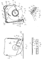
- the device for dispensing two sided adhesive tape pieces comprises a roll 1 of a carrier strip 2 holding two sided adhesive tape pieces 3.
- the tape pieces 3 may be of a conventional tape with a core of paper or plastic coated with an adhesive on both sides.
- the carrier strip 2 is likewise of a conventional type and releases easily the tape pieces 3.
- Adjacent tape pieces 3 are preferably mutually connected by means of a narrow material strip 4, a so-called 'louse'.
- the roll 1 is wound on a hub 5 with an internal, circular cogging with teeth 6.
- the roll 1 is embedded in a support 7 in the form of a moulded plastic item having an overall wall thickness of a few millimetres or less.
- the support 7 comprises a side wall 8 with an essentially quadrangular contour. From the side wall 8, a hollow stub shaft 9 rises in the form of an essentially cylindrical projection extending up through the hub 5 in order to support the roll 1 in a rotational manner.
- a peripheral wall 10 extends.
- the support 7 is open to permit the roll 1 protrude from the support 7.
- a recess 12 extends into the side wall 8, into the stub shaft 9 and down to the fourth peripheral side, a narrow material strip or a hinged portion 13 being left acting as a resilient hinge to be described further below.
- the recess 12 defines a resilient movable pressure base portion 14, the rest position of which is shown in Figs. 1 and 2.
- the pressure base portion 14 carries a pressure base element 15 essentially in the form of a J.
- a vertical part 16 of the pressure base element, as seen in Fig. 2 constitutes a part of a slide for the carrier strip 2 with tape pieces 3.
- the slide continues from the vertical part 16 through a curved part 17 to an edge 18 terminating the slide.
- the curved part 17 has a tangent direction which is approximately perpendicular to the adjacent first portion 11 of the peripheral wall 10.
- a top horizontal part 19 of the pressure base element 15 constitutes an abutment for the first adjacent wall portion 11 to limit the movement of the pressure base portion 14 in the direction toward said wall portion 11.
- a double wall 20 extends, a canal 21 being formed between the peripheral wall 10 and the double wall 20. Through this canal 21, the carrier strip 2 may pass.
- a tear-off edge 22 for tearing off the carrier strip 2.
- the pressure base portion 14 has at the stub shaft 9 a cam 23 extending down between two teeth 6 in the cogging of the hub 5 when the pressure base portion 14 is in its rest position. Both the teeth 6 and the cam 23 have, as seen in Fig. 2, essentially parallel sides, the cam 5 not being inclined to be pushed out of engagement if a force tries to turn the roll 1 while the cam 23 is in engagement with the teeth 6.
- Rotation of the roll 1 is thus prevented when the pressure base portion 14 is in its rest position, however, feasible when a sufficiently pressure on the pressure base element 15 has turned the pressure base portion 14 such that the cam 23 is out of engagement with the teeth 6.
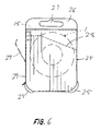
- Fig. 6 shows the support 7 with the roll 1 embedded in a box 24 essentially encompassing the support and roll, however, corners 25 of the support 7 project from the box 24.
- the box 24 has in its one end a flap 26 with a loop 27 for suspension in a sales exhibition.
- the box 24 acts thus as a sales packaging.
- the box 24 has a perforation 28 by which the end with the flap 26 can be torn off, the bottom parts of the roll 1 and the pressure base element 15 being uncovered for use of the device. It is to be noted that the device when suspended in the loop 27 has the bottom up.
- the remaining part of the box 24 acts thus as a protection of the device, prevents the roll from falling off the support 7, and makes it more comfortable for a user to seize the device without risking to seize the roll itself 1 and unintentionally impede its rotation.
- a part 29 of the side wall of the box 24 is turned away from the side wall 11 of the support as shown with a broken line in Fig. 6 in order to give access to the side wall 11 as will be described below.
- the device is used in the following way.
- the bottom part of the box is torn off along the perforation 28 and the part 29 of the side wall of the box is turned away from the side wall 11 or is completely torn off.
- the user seizes with one hand the support 7 with the double wall 20 facing the palm of the hand. With his index finger, the user pulls the carrier strip 2 along the wall portion 11 in the direction of the arrow 30. This entails a traction in the pressure base element 15 toward the adjacent wall portion 11 and the cam 23 is brought out of engagement with the teeth 6, the pressure base portion 14 being rotated about the hinged portion 13.
- a continuous traction in the carrier strip 2 along the wall portion 11 entails that the carrier strip 2 with tape pieces 3 is pulled forward from the roll 1 along the vertical part 16 and the curved part 17 of the pressure base element 15 to the edge 18. At this place, the carrier strip 2 turns sharply around the corner to continue up toward and along the wall portions 11.
- the tape pieces 3 have a rigidity which implies that they release their adhesive grip in the carrier strip 2 at the edge 18 and let themselves be forwarded in the tangent direction of the pressure base element 15 as seen in Fig. 2.
- the advance of the carrier strip 2 is stopped and the tape piece 3 is pressed against a surface 32, on which it is to be placed, e.g. a piece of paper or cardboard, subsequently to adhere a photo on the place.
- a surface 32 on which it is to be placed, e.g. a piece of paper or cardboard, subsequently to adhere a photo on the place.
- the tape piece will as it adheres to the surface 32 pull the carrier strip 2 and draw further a small length hereof off the roll 1.
- the pressure against the pressure base element 15 will thus be released and the pressure base portion 14 returns to its rest position, the cam 23 entering into locking engagement with the teeth 6 to block the roll 1.
- the tape pieces 3 will therefore be pulled free of the carrier strip 2, the louse 4 being torn.
- the user may then by means of his index finger pull a new tape piece forward.
- the carrier strip 2 which is free from tape pieces will be pushed through the channel 21 and hampers thus not the handling of the device.
- the free end of the carrier strip 2 is torn off against the tear-off edge 22.
- a substantial feature of the invention is the cooperation between the rigidity of the tape pieces 3, their attachment to the carrier strip 2 and the curve of the path of the carrier strip 2 along the pressure base 15.
- the tape pieces 3 will so far not be inclined to be separated from the carrier strip 2.
- the vertical part 16 has a tangent direction pointing essentially toward the periphery of the roll 1 before use begins.
- the lice 4 The purpose of the lice 4 is first and foremost to obtain the effect that the tape pieces 3 on the place where the carrier strip 2 is pulled away or unwound from the roll 1 will follow each other on the unwound carrier strip part and not stay on the outside of the roll 1.
- the adhesion between the carrier strip 2 and the two different sides of the tape pieces 3 could be adapted such that said effect is assured.
- the lice 4 constitute a solution technically more simple and a more reliable solution.
- the tape pieces 3 can adhere by the glue surrounding the core material.
Landscapes
- Adhesive Tapes (AREA)
- Adhesive Tape Dispensing Devices (AREA)
- Package Closures (AREA)
Priority Applications (10)
| Application Number | Priority Date | Filing Date | Title |
|---|---|---|---|
| ES02388006T ES2271208T3 (es) | 2002-01-16 | 2002-01-16 | Dispositivo para distribuir trozos de cinta adhesiva de dos caras. |
| EP02388006A EP1329407B1 (fr) | 2002-01-16 | 2002-01-16 | Dispositif pour la distribution d'un ruban adhésif des deux côtés |
| DK02388006T DK1329407T3 (da) | 2002-01-16 | 2002-01-16 | Indretning til afgivelse af dobbeltklæbende tapestykker |
| DE60214330T DE60214330T2 (de) | 2002-01-16 | 2002-01-16 | Vorrichtung zum Ausgeben von zweiseitig klebenden Klebeband |
| AT02388006T ATE338001T1 (de) | 2002-01-16 | 2002-01-16 | Vorrichtung zum ausgeben von zweiseitig klebenden klebeband |
| US10/146,908 US6945298B2 (en) | 2002-01-16 | 2002-05-17 | Device for dispensing two sided adhesive tape pieces and a refill roll for the device |
| AU2003205538A AU2003205538B2 (en) | 2002-01-16 | 2003-01-13 | A device for dispensing two sided adhesive tape pieces and a refill roll for the device |
| NZ534250A NZ534250A (en) | 2002-01-16 | 2003-01-13 | A device for dispensing two sided adhesive tape pieces and a refill roll for the device |
| PCT/DK2003/000018 WO2003059796A1 (fr) | 2002-01-16 | 2003-01-13 | Dispositif distributeur de morceaux de ruban adhesif a deux faces, et rouleau de recharge pour le dispositif |
| CA2472772A CA2472772C (fr) | 2002-01-16 | 2003-01-13 | Dispositif distributeur de morceaux de ruban adhesif a deux faces, et rouleau de recharge pour le dispositif |
Applications Claiming Priority (1)
| Application Number | Priority Date | Filing Date | Title |
|---|---|---|---|
| EP02388006A EP1329407B1 (fr) | 2002-01-16 | 2002-01-16 | Dispositif pour la distribution d'un ruban adhésif des deux côtés |
Publications (2)
| Publication Number | Publication Date |
|---|---|
| EP1329407A1 true EP1329407A1 (fr) | 2003-07-23 |
| EP1329407B1 EP1329407B1 (fr) | 2006-08-30 |
Family
ID=8185772
Family Applications (1)
| Application Number | Title | Priority Date | Filing Date |
|---|---|---|---|
| EP02388006A Expired - Lifetime EP1329407B1 (fr) | 2002-01-16 | 2002-01-16 | Dispositif pour la distribution d'un ruban adhésif des deux côtés |
Country Status (10)
| Country | Link |
|---|---|
| US (1) | US6945298B2 (fr) |
| EP (1) | EP1329407B1 (fr) |
| AT (1) | ATE338001T1 (fr) |
| AU (1) | AU2003205538B2 (fr) |
| CA (1) | CA2472772C (fr) |
| DE (1) | DE60214330T2 (fr) |
| DK (1) | DK1329407T3 (fr) |
| ES (1) | ES2271208T3 (fr) |
| NZ (1) | NZ534250A (fr) |
| WO (1) | WO2003059796A1 (fr) |
Cited By (2)
| Publication number | Priority date | Publication date | Assignee | Title |
|---|---|---|---|---|
| WO2004065274A1 (fr) * | 2003-01-23 | 2004-08-05 | 3L-Ludvigsen A/S | Dispositif de distribution de morceaux adhesifs d'un adhesif double-face |
| EP1854595A3 (fr) * | 2006-05-12 | 2010-07-21 | YMOS GmbH | Dispositif de coupe ayant un élément d'encliquetage pour faire avancer pas-à-pas une bande de masses d'équilibrage |
Families Citing this family (5)
| Publication number | Priority date | Publication date | Assignee | Title |
|---|---|---|---|---|
| US20090047460A1 (en) * | 2007-08-14 | 2009-02-19 | 3L-Ludvigsen A/S | Adhesive dispensing product |
| USD737347S1 (en) * | 2014-01-05 | 2015-08-25 | Makerbot Industries, Llc | Filament spool holder for three-dimensional printer |
| USD747374S1 (en) * | 2014-03-18 | 2016-01-12 | Makerbot Industries, Llc | Filament spool holder for three-dimensional printer |
| USD810747S1 (en) * | 2015-06-01 | 2018-02-20 | Xyzprinting, Inc. | Three dimensional scanning device |
| USD900177S1 (en) | 2019-03-19 | 2020-10-27 | Makerbot Industries, Llc | Drawer for a three-dimensional printer |
Citations (7)
| Publication number | Priority date | Publication date | Assignee | Title |
|---|---|---|---|---|
| US4704185A (en) * | 1984-10-05 | 1987-11-03 | Heinrich Hermann Gmbh + Co. | Hand-held dispenser and applicator apparatus for dispensing adhesive labels, and the like |
| US4851076A (en) * | 1986-11-13 | 1989-07-25 | Pelikan Aktiengesellschaft | Adhesive film applicator |
| US5150851A (en) * | 1988-11-05 | 1992-09-29 | Pelikan Aktiengesellschaft | Clutch for tape dispenser |
| US5178717A (en) * | 1991-03-06 | 1993-01-12 | Rodriguez Peter A | Adhesive applicator |
| US5316613A (en) * | 1991-09-06 | 1994-05-31 | Minnesota Mining And Manufacturing Company | Definite length transfer adhesive dispenser |
| JPH0710354A (ja) * | 1993-06-28 | 1995-01-13 | Sony Corp | 粘着シートの供給装置 |
| JP2000302316A (ja) * | 1999-04-21 | 2000-10-31 | Takayasu Takebe | 両面粘着テープ貼付器及び両面粘着テープの貼付方法 |
Family Cites Families (13)
| Publication number | Priority date | Publication date | Assignee | Title |
|---|---|---|---|---|
| DE1124013B (de) | 1958-01-28 | 1962-02-22 | Heinrich Hermann Fa | Fotoecke zum Zusammenschliessen zu einem Band und Verfahren zum Herstellen solcher Fotoecken auf einem gemeinsamen Traegerband |
| US3274038A (en) | 1963-01-14 | 1966-09-20 | Andrew B Karn | Dispensing device |
| US3839127A (en) | 1973-06-01 | 1974-10-01 | Minnesota Mining & Mfg | Adhesive applicator |
| JPS54134187U (fr) | 1978-03-06 | 1979-09-18 | ||
| US4396455A (en) | 1982-02-01 | 1983-08-02 | Hiromichi Uchida | Device for automatically transferring an adhesive tape to an article |
| US4718971A (en) | 1986-10-09 | 1988-01-12 | Moore Push-Pin Company | Dispenser for a transfer adhesive |
| US4851074A (en) | 1987-05-27 | 1989-07-25 | Uchida Hiromichi | Automatic transferring device for double-coated adhesive tape |
| DE3718065C1 (de) | 1987-05-28 | 1988-08-11 | Doro Tape Ehlis Kg | Handgeraet zum Auftragen eines doppelseitig klebenden Bandes zusammen mit einem Abdeckstreifen |
| DE3819845A1 (de) * | 1988-06-10 | 1990-02-01 | Minnesota Mining & Mfg | Verfahren zum definierten aufbringen von abschnitten eines bandes auf eine oberflaeche und vorrichtung zur durchfuehrung dieses verfahrens |
| GB2254289B (en) * | 1991-04-05 | 1995-03-22 | Gerber Garment Technology Inc | Readily transferrable adherent tape and methods of use and making |
| US5310437A (en) * | 1992-10-15 | 1994-05-10 | The Gillette Company | Single spool correction tape dispenser |
| US5456792A (en) * | 1993-11-15 | 1995-10-10 | Sandar Industries, Inc. | Adhesive dispenser |
| US6594927B2 (en) * | 1995-08-24 | 2003-07-22 | Magiccom | Label or wrapper with premium |
-
2002
- 2002-01-16 ES ES02388006T patent/ES2271208T3/es not_active Expired - Lifetime
- 2002-01-16 DK DK02388006T patent/DK1329407T3/da active
- 2002-01-16 DE DE60214330T patent/DE60214330T2/de not_active Expired - Lifetime
- 2002-01-16 EP EP02388006A patent/EP1329407B1/fr not_active Expired - Lifetime
- 2002-01-16 AT AT02388006T patent/ATE338001T1/de not_active IP Right Cessation
- 2002-05-17 US US10/146,908 patent/US6945298B2/en not_active Expired - Fee Related
-
2003
- 2003-01-13 WO PCT/DK2003/000018 patent/WO2003059796A1/fr not_active Ceased
- 2003-01-13 NZ NZ534250A patent/NZ534250A/en not_active IP Right Cessation
- 2003-01-13 AU AU2003205538A patent/AU2003205538B2/en not_active Ceased
- 2003-01-13 CA CA2472772A patent/CA2472772C/fr not_active Expired - Fee Related
Patent Citations (8)
| Publication number | Priority date | Publication date | Assignee | Title |
|---|---|---|---|---|
| US4704185A (en) * | 1984-10-05 | 1987-11-03 | Heinrich Hermann Gmbh + Co. | Hand-held dispenser and applicator apparatus for dispensing adhesive labels, and the like |
| US4851076A (en) * | 1986-11-13 | 1989-07-25 | Pelikan Aktiengesellschaft | Adhesive film applicator |
| US4851076B1 (en) * | 1986-11-13 | 1999-10-26 | Henkel Kgaa | Adhesive film applicator |
| US5150851A (en) * | 1988-11-05 | 1992-09-29 | Pelikan Aktiengesellschaft | Clutch for tape dispenser |
| US5178717A (en) * | 1991-03-06 | 1993-01-12 | Rodriguez Peter A | Adhesive applicator |
| US5316613A (en) * | 1991-09-06 | 1994-05-31 | Minnesota Mining And Manufacturing Company | Definite length transfer adhesive dispenser |
| JPH0710354A (ja) * | 1993-06-28 | 1995-01-13 | Sony Corp | 粘着シートの供給装置 |
| JP2000302316A (ja) * | 1999-04-21 | 2000-10-31 | Takayasu Takebe | 両面粘着テープ貼付器及び両面粘着テープの貼付方法 |
Non-Patent Citations (2)
| Title |
|---|
| PATENT ABSTRACTS OF JAPAN vol. 1995, no. 04 31 May 1995 (1995-05-31) * |
| PATENT ABSTRACTS OF JAPAN vol. 2000, no. 13 5 February 2001 (2001-02-05) * |
Cited By (2)
| Publication number | Priority date | Publication date | Assignee | Title |
|---|---|---|---|---|
| WO2004065274A1 (fr) * | 2003-01-23 | 2004-08-05 | 3L-Ludvigsen A/S | Dispositif de distribution de morceaux adhesifs d'un adhesif double-face |
| EP1854595A3 (fr) * | 2006-05-12 | 2010-07-21 | YMOS GmbH | Dispositif de coupe ayant un élément d'encliquetage pour faire avancer pas-à-pas une bande de masses d'équilibrage |
Also Published As
| Publication number | Publication date |
|---|---|
| CA2472772C (fr) | 2011-01-04 |
| US6945298B2 (en) | 2005-09-20 |
| NZ534250A (en) | 2006-01-27 |
| US20030131944A1 (en) | 2003-07-17 |
| CA2472772A1 (fr) | 2003-07-24 |
| DE60214330D1 (de) | 2006-10-12 |
| ATE338001T1 (de) | 2006-09-15 |
| EP1329407B1 (fr) | 2006-08-30 |
| WO2003059796A1 (fr) | 2003-07-24 |
| DE60214330T2 (de) | 2007-10-04 |
| DK1329407T3 (da) | 2006-10-30 |
| AU2003205538A1 (en) | 2003-07-30 |
| ES2271208T3 (es) | 2007-04-16 |
| AU2003205538B2 (en) | 2008-07-17 |
Similar Documents
| Publication | Publication Date | Title |
|---|---|---|
| EP1339547B1 (fr) | Devidoir manuel de ruban adhesif | |
| EP1690682B1 (fr) | Appareil de traitement de document | |
| EP0099917B1 (fr) | Bande de cicatrisation de blessure et son applicateur | |
| CA2451925C (fr) | Applicateur de segment adhesif mecanique a main et methode connexe | |
| AU2002219917A1 (en) | Hand-held adhesive tape dispenser | |
| US6945298B2 (en) | Device for dispensing two sided adhesive tape pieces and a refill roll for the device | |
| US6575345B2 (en) | Rolled sheet material dispenser with safer sheet cutting means | |
| MXPA02008029A (es) | Aplicacion de cinta total. | |
| US6382291B2 (en) | Dispenser for self-adhesive material | |
| EP1592633B1 (fr) | Dispositif de distribution de morceaux adhesifs d'un adhesif double-face | |
| JPH10218147A (ja) | 剥離シートなし帯状ラベルのカセット |
Legal Events
| Date | Code | Title | Description |
|---|---|---|---|
| PUAI | Public reference made under article 153(3) epc to a published international application that has entered the european phase |
Free format text: ORIGINAL CODE: 0009012 |
|
| AK | Designated contracting states |
Designated state(s): AT BE CH CY DE DK ES FI FR GB GR IE IT LI LU MC NL PT SE TR |
|
| AX | Request for extension of the european patent |
Extension state: AL LT LV MK RO SI |
|
| 17P | Request for examination filed |
Effective date: 20040122 |
|
| AKX | Designation fees paid |
Designated state(s): AT BE CH CY DE DK ES FI FR GB GR IE IT LI LU MC NL PT SE TR |
|
| 17Q | First examination report despatched |
Effective date: 20040927 |
|
| GRAP | Despatch of communication of intention to grant a patent |
Free format text: ORIGINAL CODE: EPIDOSNIGR1 |
|
| RTI1 | Title (correction) |
Free format text: DEVICE FOR DISPENSING TWO SIDED ADHESIVE TAPE PIECES |
|
| GRAS | Grant fee paid |
Free format text: ORIGINAL CODE: EPIDOSNIGR3 |
|
| GRAA | (expected) grant |
Free format text: ORIGINAL CODE: 0009210 |
|
| AK | Designated contracting states |
Kind code of ref document: B1 Designated state(s): AT BE CH CY DE DK ES FI FR GB GR IE IT LI LU MC NL PT SE TR |
|
| PG25 | Lapsed in a contracting state [announced via postgrant information from national office to epo] |
Ref country code: IT Free format text: LAPSE BECAUSE OF FAILURE TO SUBMIT A TRANSLATION OF THE DESCRIPTION OR TO PAY THE FEE WITHIN THE PRESCRIBED TIME-LIMIT;WARNING: LAPSES OF ITALIAN PATENTS WITH EFFECTIVE DATE BEFORE 2007 MAY HAVE OCCURRED AT ANY TIME BEFORE 2007. THE CORRECT EFFECTIVE DATE MAY BE DIFFERENT FROM THE ONE RECORDED. Effective date: 20060830 Ref country code: NL Free format text: LAPSE BECAUSE OF FAILURE TO SUBMIT A TRANSLATION OF THE DESCRIPTION OR TO PAY THE FEE WITHIN THE PRESCRIBED TIME-LIMIT Effective date: 20060830 Ref country code: LI Free format text: LAPSE BECAUSE OF FAILURE TO SUBMIT A TRANSLATION OF THE DESCRIPTION OR TO PAY THE FEE WITHIN THE PRESCRIBED TIME-LIMIT Effective date: 20060830 Ref country code: BE Free format text: LAPSE BECAUSE OF FAILURE TO SUBMIT A TRANSLATION OF THE DESCRIPTION OR TO PAY THE FEE WITHIN THE PRESCRIBED TIME-LIMIT Effective date: 20060830 Ref country code: AT Free format text: LAPSE BECAUSE OF FAILURE TO SUBMIT A TRANSLATION OF THE DESCRIPTION OR TO PAY THE FEE WITHIN THE PRESCRIBED TIME-LIMIT Effective date: 20060830 Ref country code: FI Free format text: LAPSE BECAUSE OF FAILURE TO SUBMIT A TRANSLATION OF THE DESCRIPTION OR TO PAY THE FEE WITHIN THE PRESCRIBED TIME-LIMIT Effective date: 20060830 Ref country code: CH Free format text: LAPSE BECAUSE OF FAILURE TO SUBMIT A TRANSLATION OF THE DESCRIPTION OR TO PAY THE FEE WITHIN THE PRESCRIBED TIME-LIMIT Effective date: 20060830 |
|
| REG | Reference to a national code |
Ref country code: GB Ref legal event code: FG4D |
|
| REG | Reference to a national code |
Ref country code: CH Ref legal event code: EP |
|
| REG | Reference to a national code |
Ref country code: IE Ref legal event code: FG4D |
|
| REF | Corresponds to: |
Ref document number: 60214330 Country of ref document: DE Date of ref document: 20061012 Kind code of ref document: P |
|
| REG | Reference to a national code |
Ref country code: DK Ref legal event code: T3 |
|
| PG25 | Lapsed in a contracting state [announced via postgrant information from national office to epo] |
Ref country code: SE Free format text: LAPSE BECAUSE OF FAILURE TO SUBMIT A TRANSLATION OF THE DESCRIPTION OR TO PAY THE FEE WITHIN THE PRESCRIBED TIME-LIMIT Effective date: 20061130 |
|
| PG25 | Lapsed in a contracting state [announced via postgrant information from national office to epo] |
Ref country code: IE Free format text: LAPSE BECAUSE OF NON-PAYMENT OF DUE FEES Effective date: 20070116 |
|
| PG25 | Lapsed in a contracting state [announced via postgrant information from national office to epo] |
Ref country code: MC Free format text: LAPSE BECAUSE OF NON-PAYMENT OF DUE FEES Effective date: 20070131 |
|
| PG25 | Lapsed in a contracting state [announced via postgrant information from national office to epo] |
Ref country code: PT Free format text: LAPSE BECAUSE OF FAILURE TO SUBMIT A TRANSLATION OF THE DESCRIPTION OR TO PAY THE FEE WITHIN THE PRESCRIBED TIME-LIMIT Effective date: 20070212 |
|
| REG | Reference to a national code |
Ref country code: CH Ref legal event code: PL |
|
| NLV1 | Nl: lapsed or annulled due to failure to fulfill the requirements of art. 29p and 29m of the patents act | ||
| ET | Fr: translation filed | ||
| REG | Reference to a national code |
Ref country code: ES Ref legal event code: FG2A Ref document number: 2271208 Country of ref document: ES Kind code of ref document: T3 |
|
| PLBE | No opposition filed within time limit |
Free format text: ORIGINAL CODE: 0009261 |
|
| STAA | Information on the status of an ep patent application or granted ep patent |
Free format text: STATUS: NO OPPOSITION FILED WITHIN TIME LIMIT |
|
| 26N | No opposition filed |
Effective date: 20070531 |
|
| PG25 | Lapsed in a contracting state [announced via postgrant information from national office to epo] |
Ref country code: GR Free format text: LAPSE BECAUSE OF FAILURE TO SUBMIT A TRANSLATION OF THE DESCRIPTION OR TO PAY THE FEE WITHIN THE PRESCRIBED TIME-LIMIT Effective date: 20061201 |
|
| PG25 | Lapsed in a contracting state [announced via postgrant information from national office to epo] |
Ref country code: LU Free format text: LAPSE BECAUSE OF NON-PAYMENT OF DUE FEES Effective date: 20070116 Ref country code: CY Free format text: LAPSE BECAUSE OF FAILURE TO SUBMIT A TRANSLATION OF THE DESCRIPTION OR TO PAY THE FEE WITHIN THE PRESCRIBED TIME-LIMIT Effective date: 20060830 |
|
| PG25 | Lapsed in a contracting state [announced via postgrant information from national office to epo] |
Ref country code: TR Free format text: LAPSE BECAUSE OF FAILURE TO SUBMIT A TRANSLATION OF THE DESCRIPTION OR TO PAY THE FEE WITHIN THE PRESCRIBED TIME-LIMIT Effective date: 20060830 |
|
| PGFP | Annual fee paid to national office [announced via postgrant information from national office to epo] |
Ref country code: FR Payment date: 20120209 Year of fee payment: 11 |
|
| PGFP | Annual fee paid to national office [announced via postgrant information from national office to epo] |
Ref country code: DE Payment date: 20120125 Year of fee payment: 11 |
|
| PGFP | Annual fee paid to national office [announced via postgrant information from national office to epo] |
Ref country code: IT Payment date: 20120124 Year of fee payment: 11 Ref country code: DK Payment date: 20120125 Year of fee payment: 11 Ref country code: GB Payment date: 20120130 Year of fee payment: 11 |
|
| PGFP | Annual fee paid to national office [announced via postgrant information from national office to epo] |
Ref country code: ES Payment date: 20120123 Year of fee payment: 11 |
|
| REG | Reference to a national code |
Ref country code: DK Ref legal event code: EBP |
|
| GBPC | Gb: european patent ceased through non-payment of renewal fee |
Effective date: 20130116 |
|
| REG | Reference to a national code |
Ref country code: FR Ref legal event code: ST Effective date: 20130930 |
|
| PG25 | Lapsed in a contracting state [announced via postgrant information from national office to epo] |
Ref country code: DE Free format text: LAPSE BECAUSE OF NON-PAYMENT OF DUE FEES Effective date: 20130801 |
|
| REG | Reference to a national code |
Ref country code: DE Ref legal event code: R119 Ref document number: 60214330 Country of ref document: DE Effective date: 20130801 |
|
| PG25 | Lapsed in a contracting state [announced via postgrant information from national office to epo] |
Ref country code: FR Free format text: LAPSE BECAUSE OF NON-PAYMENT OF DUE FEES Effective date: 20130131 Ref country code: GB Free format text: LAPSE BECAUSE OF NON-PAYMENT OF DUE FEES Effective date: 20130116 |
|
| PG25 | Lapsed in a contracting state [announced via postgrant information from national office to epo] |
Ref country code: IT Free format text: LAPSE BECAUSE OF NON-PAYMENT OF DUE FEES Effective date: 20130116 |
|
| PG25 | Lapsed in a contracting state [announced via postgrant information from national office to epo] |
Ref country code: DK Free format text: LAPSE BECAUSE OF NON-PAYMENT OF DUE FEES Effective date: 20130131 |
|
| REG | Reference to a national code |
Ref country code: ES Ref legal event code: FD2A Effective date: 20140509 |
|
| PG25 | Lapsed in a contracting state [announced via postgrant information from national office to epo] |
Ref country code: ES Free format text: LAPSE BECAUSE OF NON-PAYMENT OF DUE FEES Effective date: 20130117 |