EP1329472B1 - Epoxidharzzusammensetzung, Verfahren zur Oberflächenmodifizierung, Tintenstrahlaufzeichnungskopf und Tintenstrahlaufzeichnungsapparat - Google Patents
Epoxidharzzusammensetzung, Verfahren zur Oberflächenmodifizierung, Tintenstrahlaufzeichnungskopf und Tintenstrahlaufzeichnungsapparat Download PDFInfo
- Publication number
- EP1329472B1 EP1329472B1 EP03000885A EP03000885A EP1329472B1 EP 1329472 B1 EP1329472 B1 EP 1329472B1 EP 03000885 A EP03000885 A EP 03000885A EP 03000885 A EP03000885 A EP 03000885A EP 1329472 B1 EP1329472 B1 EP 1329472B1
- Authority
- EP
- European Patent Office
- Prior art keywords
- epoxy resin
- coating
- resin composition
- group
- denotes
- Prior art date
- Legal status (The legal status is an assumption and is not a legal conclusion. Google has not performed a legal analysis and makes no representation as to the accuracy of the status listed.)
- Expired - Lifetime
Links
- 239000003822 epoxy resin Substances 0.000 title claims abstract description 95
- 229920000647 polyepoxide Polymers 0.000 title claims abstract description 95
- 239000000203 mixture Substances 0.000 title claims abstract description 69
- 238000000034 method Methods 0.000 title claims description 30
- 230000008569 process Effects 0.000 title description 10
- 238000012986 modification Methods 0.000 title description 6
- 230000004048 modification Effects 0.000 title description 6
- 238000010538 cationic polymerization reaction Methods 0.000 claims abstract description 6
- 239000002685 polymerization catalyst Substances 0.000 claims abstract description 6
- 239000011248 coating agent Substances 0.000 claims description 88
- 238000000576 coating method Methods 0.000 claims description 87
- 239000007788 liquid Substances 0.000 claims description 67
- 239000000178 monomer Substances 0.000 claims description 18
- 150000001875 compounds Chemical class 0.000 claims description 17
- 125000000217 alkyl group Chemical group 0.000 claims description 12
- 125000004435 hydrogen atom Chemical group [H]* 0.000 claims description 12
- 125000003709 fluoroalkyl group Chemical group 0.000 claims description 4
- 230000001678 irradiating effect Effects 0.000 claims description 3
- 230000000379 polymerizing effect Effects 0.000 claims description 3
- 125000002947 alkylene group Chemical group 0.000 claims description 2
- 125000002496 methyl group Chemical group [H]C([H])([H])* 0.000 claims description 2
- 125000002560 nitrile group Chemical group 0.000 claims description 2
- 125000005010 perfluoroalkyl group Chemical group 0.000 claims description 2
- 125000001997 phenyl group Chemical group [H]C1=C([H])C([H])=C(*)C([H])=C1[H] 0.000 claims description 2
- 125000005376 alkyl siloxane group Chemical group 0.000 claims 1
- 239000000976 ink Substances 0.000 description 44
- 239000000463 material Substances 0.000 description 29
- 239000002585 base Substances 0.000 description 27
- 239000011342 resin composition Substances 0.000 description 20
- XLYOFNOQVPJJNP-UHFFFAOYSA-N water Substances O XLYOFNOQVPJJNP-UHFFFAOYSA-N 0.000 description 18
- 239000003054 catalyst Substances 0.000 description 14
- 238000007639 printing Methods 0.000 description 14
- 238000004381 surface treatment Methods 0.000 description 13
- 239000002904 solvent Substances 0.000 description 12
- 239000003795 chemical substances by application Substances 0.000 description 10
- 239000003973 paint Substances 0.000 description 10
- 229920000642 polymer Polymers 0.000 description 9
- 239000005871 repellent Substances 0.000 description 9
- 238000010438 heat treatment Methods 0.000 description 8
- 239000000126 substance Substances 0.000 description 8
- 238000004140 cleaning Methods 0.000 description 7
- 238000011156 evaluation Methods 0.000 description 7
- 230000007774 longterm Effects 0.000 description 7
- 229920005989 resin Polymers 0.000 description 7
- 239000011347 resin Substances 0.000 description 7
- 238000011161 development Methods 0.000 description 6
- 230000005499 meniscus Effects 0.000 description 6
- 239000003495 polar organic solvent Substances 0.000 description 6
- 239000002841 Lewis acid Substances 0.000 description 5
- 150000007517 lewis acids Chemical class 0.000 description 5
- 238000000059 patterning Methods 0.000 description 5
- -1 perfluoro group Chemical group 0.000 description 5
- 238000012360 testing method Methods 0.000 description 5
- PEDCQBHIVMGVHV-UHFFFAOYSA-N Glycerine Chemical compound OCC(O)CO PEDCQBHIVMGVHV-UHFFFAOYSA-N 0.000 description 4
- 239000003086 colorant Substances 0.000 description 4
- 230000000052 comparative effect Effects 0.000 description 4
- 238000005259 measurement Methods 0.000 description 4
- 239000004593 Epoxy Substances 0.000 description 3
- HEMHJVSKTPXQMS-UHFFFAOYSA-M Sodium hydroxide Chemical compound [OH-].[Na+] HEMHJVSKTPXQMS-UHFFFAOYSA-M 0.000 description 3
- YXFVVABEGXRONW-UHFFFAOYSA-N Toluene Chemical compound CC1=CC=CC=C1 YXFVVABEGXRONW-UHFFFAOYSA-N 0.000 description 3
- 239000002250 absorbent Substances 0.000 description 3
- 230000002745 absorbent Effects 0.000 description 3
- 239000011230 binding agent Substances 0.000 description 3
- 230000015572 biosynthetic process Effects 0.000 description 3
- 238000006243 chemical reaction Methods 0.000 description 3
- 238000001035 drying Methods 0.000 description 3
- 230000000694 effects Effects 0.000 description 3
- 150000002148 esters Chemical class 0.000 description 3
- 239000002075 main ingredient Substances 0.000 description 3
- QSHDDOUJBYECFT-UHFFFAOYSA-N mercury Chemical compound [Hg] QSHDDOUJBYECFT-UHFFFAOYSA-N 0.000 description 3
- 238000002156 mixing Methods 0.000 description 3
- 239000003960 organic solvent Substances 0.000 description 3
- 238000000206 photolithography Methods 0.000 description 3
- 229920002120 photoresistant polymer Polymers 0.000 description 3
- 238000011084 recovery Methods 0.000 description 3
- 150000003839 salts Chemical class 0.000 description 3
- 239000007787 solid Substances 0.000 description 3
- 238000009281 ultraviolet germicidal irradiation Methods 0.000 description 3
- XTHFKEDIFFGKHM-UHFFFAOYSA-N Dimethoxyethane Chemical compound COCCOC XTHFKEDIFFGKHM-UHFFFAOYSA-N 0.000 description 2
- LFQSCWFLJHTTHZ-UHFFFAOYSA-N Ethanol Chemical compound CCO LFQSCWFLJHTTHZ-UHFFFAOYSA-N 0.000 description 2
- 238000005299 abrasion Methods 0.000 description 2
- 150000004945 aromatic hydrocarbons Chemical class 0.000 description 2
- 239000004035 construction material Substances 0.000 description 2
- 230000000593 degrading effect Effects 0.000 description 2
- ZBCBWPMODOFKDW-UHFFFAOYSA-N diethanolamine Chemical compound OCCNCCO ZBCBWPMODOFKDW-UHFFFAOYSA-N 0.000 description 2
- 238000010894 electron beam technology Methods 0.000 description 2
- 125000003700 epoxy group Chemical group 0.000 description 2
- LYCAIKOWRPUZTN-UHFFFAOYSA-N ethylene glycol Natural products OCCO LYCAIKOWRPUZTN-UHFFFAOYSA-N 0.000 description 2
- 235000011187 glycerol Nutrition 0.000 description 2
- LNEPOXFFQSENCJ-UHFFFAOYSA-N haloperidol Chemical compound C1CC(O)(C=2C=CC(Cl)=CC=2)CCN1CCCC(=O)C1=CC=C(F)C=C1 LNEPOXFFQSENCJ-UHFFFAOYSA-N 0.000 description 2
- WGCNASOHLSPBMP-UHFFFAOYSA-N hydroxyacetaldehyde Natural products OCC=O WGCNASOHLSPBMP-UHFFFAOYSA-N 0.000 description 2
- 238000007654 immersion Methods 0.000 description 2
- 238000010348 incorporation Methods 0.000 description 2
- 150000002576 ketones Chemical class 0.000 description 2
- 238000003475 lamination Methods 0.000 description 2
- 229910052753 mercury Inorganic materials 0.000 description 2
- 239000003505 polymerization initiator Substances 0.000 description 2
- 238000006116 polymerization reaction Methods 0.000 description 2
- 238000000935 solvent evaporation Methods 0.000 description 2
- 238000004528 spin coating Methods 0.000 description 2
- 239000004094 surface-active agent Substances 0.000 description 2
- 229920002554 vinyl polymer Polymers 0.000 description 2
- WRIDQFICGBMAFQ-UHFFFAOYSA-N (E)-8-Octadecenoic acid Natural products CCCCCCCCCC=CCCCCCCC(O)=O WRIDQFICGBMAFQ-UHFFFAOYSA-N 0.000 description 1
- FABAOYOFJNAVHB-KVVVOXFISA-N (z)-octadec-9-enoic acid;propane-1,2,3-triol Chemical compound OCC(O)CO.CCCCCCCC\C=C/CCCCCCCC(O)=O FABAOYOFJNAVHB-KVVVOXFISA-N 0.000 description 1
- KUBDPQJOLOUJRM-UHFFFAOYSA-N 2-(chloromethyl)oxirane;4-[2-(4-hydroxyphenyl)propan-2-yl]phenol Chemical compound ClCC1CO1.C=1C=C(O)C=CC=1C(C)(C)C1=CC=C(O)C=C1 KUBDPQJOLOUJRM-UHFFFAOYSA-N 0.000 description 1
- OGKXDOHOOONBIR-UHFFFAOYSA-N 2-[[1,1,1,3,3,3-hexafluoro-2-[3-[1,1,1,3,3,3-hexafluoro-2-(oxiran-2-ylmethoxy)propan-2-yl]phenyl]propan-2-yl]oxymethyl]oxirane Chemical compound C=1C=CC(C(OCC2OC2)(C(F)(F)F)C(F)(F)F)=CC=1C(C(F)(F)F)(C(F)(F)F)OCC1CO1 OGKXDOHOOONBIR-UHFFFAOYSA-N 0.000 description 1
- IEMNEAVSEGLTHB-UHFFFAOYSA-N 2-[[4-[1,1,1,3,3,3-hexafluoro-2-[4-(oxiran-2-ylmethoxy)phenyl]propan-2-yl]phenoxy]methyl]oxirane Chemical compound C=1C=C(OCC2OC2)C=CC=1C(C(F)(F)F)(C(F)(F)F)C(C=C1)=CC=C1OCC1CO1 IEMNEAVSEGLTHB-UHFFFAOYSA-N 0.000 description 1
- LQJBNNIYVWPHFW-UHFFFAOYSA-N 20:1omega9c fatty acid Natural products CCCCCCCCCCC=CCCCCCCCC(O)=O LQJBNNIYVWPHFW-UHFFFAOYSA-N 0.000 description 1
- ZBRZSJUFJUMKIM-UHFFFAOYSA-N 3-(1-phenylpropan-2-ylamino)propanenitrile;hydrochloride Chemical compound Cl.N#CCCNC(C)CC1=CC=CC=C1 ZBRZSJUFJUMKIM-UHFFFAOYSA-N 0.000 description 1
- QSBYPNXLFMSGKH-UHFFFAOYSA-N 9-Heptadecensaeure Natural products CCCCCCCC=CCCCCCCCC(O)=O QSBYPNXLFMSGKH-UHFFFAOYSA-N 0.000 description 1
- 239000004925 Acrylic resin Substances 0.000 description 1
- 229920000178 Acrylic resin Polymers 0.000 description 1
- ZOXJGFHDIHLPTG-UHFFFAOYSA-N Boron Chemical compound [B] ZOXJGFHDIHLPTG-UHFFFAOYSA-N 0.000 description 1
- BRLQWZUYTZBJKN-UHFFFAOYSA-N Epichlorohydrin Chemical compound ClCC1CO1 BRLQWZUYTZBJKN-UHFFFAOYSA-N 0.000 description 1
- VGGSQFUCUMXWEO-UHFFFAOYSA-N Ethene Chemical compound C=C VGGSQFUCUMXWEO-UHFFFAOYSA-N 0.000 description 1
- 239000005977 Ethylene Substances 0.000 description 1
- YCKRFDGAMUMZLT-UHFFFAOYSA-N Fluorine atom Chemical compound [F] YCKRFDGAMUMZLT-UHFFFAOYSA-N 0.000 description 1
- SECXISVLQFMRJM-UHFFFAOYSA-N N-Methylpyrrolidone Chemical compound CN1CCCC1=O SECXISVLQFMRJM-UHFFFAOYSA-N 0.000 description 1
- 239000005642 Oleic acid Substances 0.000 description 1
- ZQPPMHVWECSIRJ-UHFFFAOYSA-N Oleic acid Natural products CCCCCCCCC=CCCCCCCCC(O)=O ZQPPMHVWECSIRJ-UHFFFAOYSA-N 0.000 description 1
- 239000004695 Polyether sulfone Substances 0.000 description 1
- 239000006087 Silane Coupling Agent Substances 0.000 description 1
- XUIMIQQOPSSXEZ-UHFFFAOYSA-N Silicon Chemical compound [Si] XUIMIQQOPSSXEZ-UHFFFAOYSA-N 0.000 description 1
- XTXRWKRVRITETP-UHFFFAOYSA-N Vinyl acetate Chemical compound CC(=O)OC=C XTXRWKRVRITETP-UHFFFAOYSA-N 0.000 description 1
- MFIBZDZRPYQXOM-UHFFFAOYSA-N [dimethyl-[3-(oxiran-2-ylmethoxy)propyl]silyl]oxy-dimethyl-[3-(oxiran-2-ylmethoxy)propyl]silane Chemical compound C1OC1COCCC[Si](C)(C)O[Si](C)(C)CCCOCC1CO1 MFIBZDZRPYQXOM-UHFFFAOYSA-N 0.000 description 1
- 150000008065 acid anhydrides Chemical class 0.000 description 1
- 230000002411 adverse Effects 0.000 description 1
- 150000001338 aliphatic hydrocarbons Chemical class 0.000 description 1
- 239000003513 alkali Substances 0.000 description 1
- PNEYBMLMFCGWSK-UHFFFAOYSA-N aluminium oxide Inorganic materials [O-2].[O-2].[O-2].[Al+3].[Al+3] PNEYBMLMFCGWSK-UHFFFAOYSA-N 0.000 description 1
- 150000004982 aromatic amines Chemical class 0.000 description 1
- 239000003849 aromatic solvent Substances 0.000 description 1
- 238000010420 art technique Methods 0.000 description 1
- DNFSNYQTQMVTOK-UHFFFAOYSA-N bis(4-tert-butylphenyl)iodanium Chemical class C1=CC(C(C)(C)C)=CC=C1[I+]C1=CC=C(C(C)(C)C)C=C1 DNFSNYQTQMVTOK-UHFFFAOYSA-N 0.000 description 1
- ZFVMWEVVKGLCIJ-UHFFFAOYSA-N bisphenol AF Chemical compound C1=CC(O)=CC=C1C(C(F)(F)F)(C(F)(F)F)C1=CC=C(O)C=C1 ZFVMWEVVKGLCIJ-UHFFFAOYSA-N 0.000 description 1
- 238000009835 boiling Methods 0.000 description 1
- 229910052796 boron Inorganic materials 0.000 description 1
- 125000004432 carbon atom Chemical group C* 0.000 description 1
- 235000019241 carbon black Nutrition 0.000 description 1
- 239000000470 constituent Substances 0.000 description 1
- 230000008602 contraction Effects 0.000 description 1
- 238000004132 cross linking Methods 0.000 description 1
- 238000000354 decomposition reaction Methods 0.000 description 1
- 150000004985 diamines Chemical class 0.000 description 1
- 229940098237 dicel Drugs 0.000 description 1
- 238000007607 die coating method Methods 0.000 description 1
- 238000007599 discharging Methods 0.000 description 1
- 239000006185 dispersion Substances 0.000 description 1
- 238000004090 dissolution Methods 0.000 description 1
- 239000000428 dust Substances 0.000 description 1
- 150000002170 ethers Chemical class 0.000 description 1
- 229910052731 fluorine Inorganic materials 0.000 description 1
- 239000011737 fluorine Substances 0.000 description 1
- 125000000524 functional group Chemical group 0.000 description 1
- 230000009477 glass transition Effects 0.000 description 1
- 238000007756 gravure coating Methods 0.000 description 1
- 230000007062 hydrolysis Effects 0.000 description 1
- 238000006460 hydrolysis reaction Methods 0.000 description 1
- 230000001771 impaired effect Effects 0.000 description 1
- 238000007641 inkjet printing Methods 0.000 description 1
- 238000003780 insertion Methods 0.000 description 1
- 230000037431 insertion Effects 0.000 description 1
- QXJSBBXBKPUZAA-UHFFFAOYSA-N isooleic acid Natural products CCCCCCCC=CCCCCCCCCC(O)=O QXJSBBXBKPUZAA-UHFFFAOYSA-N 0.000 description 1
- 230000007246 mechanism Effects 0.000 description 1
- 239000012046 mixed solvent Substances 0.000 description 1
- ZQPPMHVWECSIRJ-KTKRTIGZSA-N oleic acid Chemical compound CCCCCCCC\C=C/CCCCCCCC(O)=O ZQPPMHVWECSIRJ-KTKRTIGZSA-N 0.000 description 1
- 239000005011 phenolic resin Substances 0.000 description 1
- 239000002798 polar solvent Substances 0.000 description 1
- 229920006122 polyamide resin Polymers 0.000 description 1
- 229920005668 polycarbonate resin Polymers 0.000 description 1
- 239000004431 polycarbonate resin Substances 0.000 description 1
- 229920001225 polyester resin Polymers 0.000 description 1
- 239000004645 polyester resin Substances 0.000 description 1
- 229920000570 polyether Polymers 0.000 description 1
- 229920006393 polyether sulfone Polymers 0.000 description 1
- 229920001721 polyimide Polymers 0.000 description 1
- 239000009719 polyimide resin Substances 0.000 description 1
- 230000002265 prevention Effects 0.000 description 1
- 230000005855 radiation Effects 0.000 description 1
- 230000002940 repellent Effects 0.000 description 1
- 238000007650 screen-printing Methods 0.000 description 1
- 229910052710 silicon Inorganic materials 0.000 description 1
- 239000010703 silicon Substances 0.000 description 1
- 238000001228 spectrum Methods 0.000 description 1
- 239000007921 spray Substances 0.000 description 1
- 238000005507 spraying Methods 0.000 description 1
- 230000003068 static effect Effects 0.000 description 1
- 238000007669 thermal treatment Methods 0.000 description 1
- 229920001187 thermosetting polymer Polymers 0.000 description 1
- GWAKFAUFNNPZFE-UHFFFAOYSA-K trisodium 2-[4-[(2-amino-4-oxidophenyl)diazenyl]anilino]-5-[(1-amino-8-oxido-7-phenyldiazenyl-3,6-disulfonaphthalen-2-yl)diazenyl]benzenesulfonate Chemical compound NC1=C(C(=CC2=CC(=C(C(=C12)O)N=NC1=CC=CC=C1)S(=O)(=O)[O-])S(=O)(=O)[O-])N=NC1=CC(=C(C=C1)NC1=CC=C(C=C1)N=NC1=C(C=C(C=C1)O)N)S(=O)(=O)[O-].[Na+].[Na+].[Na+] GWAKFAUFNNPZFE-UHFFFAOYSA-K 0.000 description 1
- 125000000391 vinyl group Chemical group [H]C([*])=C([H])[H] 0.000 description 1
Images


Classifications
-
- C—CHEMISTRY; METALLURGY
- C08—ORGANIC MACROMOLECULAR COMPOUNDS; THEIR PREPARATION OR CHEMICAL WORKING-UP; COMPOSITIONS BASED THEREON
- C08L—COMPOSITIONS OF MACROMOLECULAR COMPOUNDS
- C08L63/00—Compositions of epoxy resins; Compositions of derivatives of epoxy resins
-
- C—CHEMISTRY; METALLURGY
- C08—ORGANIC MACROMOLECULAR COMPOUNDS; THEIR PREPARATION OR CHEMICAL WORKING-UP; COMPOSITIONS BASED THEREON
- C08G—MACROMOLECULAR COMPOUNDS OBTAINED OTHERWISE THAN BY REACTIONS ONLY INVOLVING UNSATURATED CARBON-TO-CARBON BONDS
- C08G59/00—Polycondensates containing more than one epoxy group per molecule; Macromolecules obtained by polymerising compounds containing more than one epoxy group per molecule using curing agents or catalysts which react with the epoxy groups
- C08G59/18—Macromolecules obtained by polymerising compounds containing more than one epoxy group per molecule using curing agents or catalysts which react with the epoxy groups ; e.g. general methods of curing
- C08G59/68—Macromolecules obtained by polymerising compounds containing more than one epoxy group per molecule using curing agents or catalysts which react with the epoxy groups ; e.g. general methods of curing characterised by the catalysts used
-
- B—PERFORMING OPERATIONS; TRANSPORTING
- B41—PRINTING; LINING MACHINES; TYPEWRITERS; STAMPS
- B41J—TYPEWRITERS; SELECTIVE PRINTING MECHANISMS, i.e. MECHANISMS PRINTING OTHERWISE THAN FROM A FORME; CORRECTION OF TYPOGRAPHICAL ERRORS
- B41J2/00—Typewriters or selective printing mechanisms characterised by the printing or marking process for which they are designed
- B41J2/005—Typewriters or selective printing mechanisms characterised by the printing or marking process for which they are designed characterised by bringing liquid or particles selectively into contact with a printing material
- B41J2/01—Ink jet
- B41J2/135—Nozzles
- B41J2/16—Production of nozzles
- B41J2/1606—Coating the nozzle area or the ink chamber
-
- C—CHEMISTRY; METALLURGY
- C08—ORGANIC MACROMOLECULAR COMPOUNDS; THEIR PREPARATION OR CHEMICAL WORKING-UP; COMPOSITIONS BASED THEREON
- C08G—MACROMOLECULAR COMPOUNDS OBTAINED OTHERWISE THAN BY REACTIONS ONLY INVOLVING UNSATURATED CARBON-TO-CARBON BONDS
- C08G59/00—Polycondensates containing more than one epoxy group per molecule; Macromolecules obtained by polymerising compounds containing more than one epoxy group per molecule using curing agents or catalysts which react with the epoxy groups
- C08G59/18—Macromolecules obtained by polymerising compounds containing more than one epoxy group per molecule using curing agents or catalysts which react with the epoxy groups ; e.g. general methods of curing
- C08G59/20—Macromolecules obtained by polymerising compounds containing more than one epoxy group per molecule using curing agents or catalysts which react with the epoxy groups ; e.g. general methods of curing characterised by the epoxy compounds used
- C08G59/22—Di-epoxy compounds
- C08G59/226—Mixtures of di-epoxy compounds
-
- C—CHEMISTRY; METALLURGY
- C08—ORGANIC MACROMOLECULAR COMPOUNDS; THEIR PREPARATION OR CHEMICAL WORKING-UP; COMPOSITIONS BASED THEREON
- C08G—MACROMOLECULAR COMPOUNDS OBTAINED OTHERWISE THAN BY REACTIONS ONLY INVOLVING UNSATURATED CARBON-TO-CARBON BONDS
- C08G59/00—Polycondensates containing more than one epoxy group per molecule; Macromolecules obtained by polymerising compounds containing more than one epoxy group per molecule using curing agents or catalysts which react with the epoxy groups
- C08G59/18—Macromolecules obtained by polymerising compounds containing more than one epoxy group per molecule using curing agents or catalysts which react with the epoxy groups ; e.g. general methods of curing
- C08G59/20—Macromolecules obtained by polymerising compounds containing more than one epoxy group per molecule using curing agents or catalysts which react with the epoxy groups ; e.g. general methods of curing characterised by the epoxy compounds used
- C08G59/22—Di-epoxy compounds
- C08G59/30—Di-epoxy compounds containing atoms other than carbon, hydrogen, oxygen and nitrogen
-
- C—CHEMISTRY; METALLURGY
- C08—ORGANIC MACROMOLECULAR COMPOUNDS; THEIR PREPARATION OR CHEMICAL WORKING-UP; COMPOSITIONS BASED THEREON
- C08G—MACROMOLECULAR COMPOUNDS OBTAINED OTHERWISE THAN BY REACTIONS ONLY INVOLVING UNSATURATED CARBON-TO-CARBON BONDS
- C08G59/00—Polycondensates containing more than one epoxy group per molecule; Macromolecules obtained by polymerising compounds containing more than one epoxy group per molecule using curing agents or catalysts which react with the epoxy groups
- C08G59/18—Macromolecules obtained by polymerising compounds containing more than one epoxy group per molecule using curing agents or catalysts which react with the epoxy groups ; e.g. general methods of curing
- C08G59/20—Macromolecules obtained by polymerising compounds containing more than one epoxy group per molecule using curing agents or catalysts which react with the epoxy groups ; e.g. general methods of curing characterised by the epoxy compounds used
- C08G59/32—Epoxy compounds containing three or more epoxy groups
- C08G59/3254—Epoxy compounds containing three or more epoxy groups containing atoms other than carbon, hydrogen, oxygen or nitrogen
-
- C—CHEMISTRY; METALLURGY
- C08—ORGANIC MACROMOLECULAR COMPOUNDS; THEIR PREPARATION OR CHEMICAL WORKING-UP; COMPOSITIONS BASED THEREON
- C08G—MACROMOLECULAR COMPOUNDS OBTAINED OTHERWISE THAN BY REACTIONS ONLY INVOLVING UNSATURATED CARBON-TO-CARBON BONDS
- C08G59/00—Polycondensates containing more than one epoxy group per molecule; Macromolecules obtained by polymerising compounds containing more than one epoxy group per molecule using curing agents or catalysts which react with the epoxy groups
- C08G59/18—Macromolecules obtained by polymerising compounds containing more than one epoxy group per molecule using curing agents or catalysts which react with the epoxy groups ; e.g. general methods of curing
- C08G59/20—Macromolecules obtained by polymerising compounds containing more than one epoxy group per molecule using curing agents or catalysts which react with the epoxy groups ; e.g. general methods of curing characterised by the epoxy compounds used
- C08G59/32—Epoxy compounds containing three or more epoxy groups
- C08G59/38—Epoxy compounds containing three or more epoxy groups together with di-epoxy compounds
Definitions
- the present invention relates to a curable epoxy resin composition useful for surface treatment to impart water-repellency or ink-repellency to an article surface, especially to an epoxy resin composition for forming a coated film (coating) in a pattern by UV irradiation.
- the present invention also relates to a surface treatment method employing the epoxy resin composition; a liquid ejection recording head having been treated for ink repellency with the resin composition; and a liquid ejection recording apparatus employing the liquid ejection recording head.
- the coating formed from a fluorine-type paint having a fluoropolyolefin group or a perfluoro group is sufficiently stable thermally and chemically, being excellent in weatherability, water resistance, chemical resistance, solvent resistance, and the like properties.
- Such coating has high mold releasability, abrasion resistance, and water repellency, and are used in various application fields.
- liquid ejection recording heads which eject liquid droplets through an ejection orifice onto a paper sheet or a like recording medium to conduct recording or to form an image, are being improved for higher recording performance with a smaller liquid droplet size, a higher driving frequency, and a larger number of nozzles. Therefore, the treatment to keep the surface condition of the nozzles unchanged is becoming more important.
- the paint should be mainly composed of a substance having a photosensitive functional group, but such a molecule of the compound cannot readily be designed to be additionally water-repellent or ink-repellent.
- the coating structure should be designed to keep the surface properties for a long period of time.
- the surface treatment material giving the above properties in a pattern is highly useful in treatment of the surface of a liquid ejection recording head (ink-jet printing head) as explained below.
- the ejection orifice (opening) is preferably designed to have the performance below:
- the ejection orifice should have the above properties, because the recording liquid like an ink adhering to periphery of the orifice will cause deviation of the direction of the ejection (flight) of the liquid droplets to render the printing imprecise and will impair the printing performance directly.
- Methods of water-repellency treatment of the ejection orifice face are known for prevention of adhesion of liquid at or around the ejection orifice so as not to cause deviation of the ejection direction.
- An example of the related prior art techniques is an ink-repellency treatment with a polymer having a fluoroacetyl group and a silazane group (e.g., Japanese Patent Application Laid-Open No. 2-39944, etc.)
- a printer of the liquid ejection recording system the properties of the recording liquid are required to be improved further. Since, such a recording liquid is usually formulated to be basic (pH 7-11) for higher dissolution stability or higher dispersion stability of the contents, the members of the printer are preferably made from a construction material having high alkali resistance and high hydrolysis resistance.
- the recording liquid contains a polar organic solvent or has a high pH value
- a water-repellency imparting agent applied to conduct surface treatment of the ejection orifice face for the above described purposes comes into contact with a solvent component used in the recording liquid, especially a polar organic solvent component
- the formability of the resulting water-repellent coating or its adhesion with the coated member is often impaired, so that the water-repellent coating peels off to cause loss of water repellency of the ejection orifice face.
- An object of the present invention is to provide an epoxy resin composition which is suitable for a water-repellency imparting agent or a water-repellent paint to be used at the portion where a solution or a material containing the component which will impair the coating formability or coating adhesiveness of the water repellent coating, like a polar solvent.
- Another object of the present invention is to provide an epoxy resin composition which is capable of surface modification treatment to keep the surface condition unchanged.
- Still another object of the present invention is to provide a surface treatment method for imparting water repellency on a surface of an article with positional selectivity.
- a further object of the present invention is to provide a liquid ejection recording head in which the surface of a base material thereof is treated with the aforementioned epoxy resin composition to keep the nozzle surface condition unchanged and to prevent ink adhesion to the print head surface even after long-term contact with a recording medium, whereby achieving high impact precision of dots and high printing quality kept for a long period of time, and also to provide a liquid ejection recording apparatus employing the liquid ejection recording head.
- the epoxy resin composition comprises:
- the surface treatment method comprises the steps of
- the surface treatment method comprises the steps of
- the liquid ejection recording head having an ejection orifice for ejecting a liquid is coated at least at the periphery of the ejection orifice with the cured coating of the epoxy resin composition.
- the liquid ejection recording apparatus has the aforementioned liquid ejection recording head.
- the coating (cured product) composed of the epoxy resin composition of the present invention has excellent adhesion to various kinds of materials, is curable even at a relatively low temperature, and has satisfactory properties as a construction material. Further, the coating has remarkably improved resistance to water-soluble organic solvents, especially polar organic solvents owing to incorporation of the epoxy resin having the water-repellency-imparting group. Further incorporation of a compatibilizer gives compatibility between the components in the resin composition to broaden the range of the material constitution of the resin composition of the present invention.
- the coating formed by applying and drying the epoxy resin composition of the present invention, which contains an onium salt of a Lewis acid capable of being activated by an active energy ray, can be cured in a pattern. Therefore, a surface of an article can be surface-treated in a pattern by removing the uncured portion of the coating.
- the surface treatment in a pattern can be conducted, for example, through the steps of applying an epoxy resin composition on a base material and drying it to form a coating, applying an active energy ray through a mask in a prescribed pattern onto the coating, and conducting development with a developing liquid to remove the uncured portion of the coating.
- the process of this patterning treatment is basically similar to photolithography.
- the developing liquid is selected from a solvent or a solvent composition suitable for the coating composed of the resin composition.
- the developing liquid is thus selected from aromatic hydrocarbons, ketones, esters, glycol ethers, and the like; and mixtures thereof.
- the epoxy resin composition of the present invention is a combination of a first epoxy resin having a relatively high molecular weight and having a water-repellency-imparting group and a second epoxy resin having a relatively low molecular weight and having a water-repellency-imparting group. This combination can provide excellent coating properties and patterning properties (giving a high image resolution and excellent pattern profile) aw well as high water repellency.
- the epoxy resin composition of the present invention is useful as a water repellency imparting agent or a water-repelling paint for application onto the portions that may be brought into contact with a solution or a material containing a component like a polar organic solvent which will impair adhesiveness of the water repellency.
- This epoxy resin composition is also useful for water- or ink-repellency treatment of the ejection orifice face of the liquid ejection recording head.
- the application of the resin composition of the present invention to the ink-jet recording apparatus gives the effects of selective surface modification by utilizing photo-polymerizability, high precision of the treatment, high solid strength of a cured coating, high durability of the device owing to improved friction strength.
- the high water- or ink-repellency improves the meniscus retainability of aqueous inks, cleanability, precision of liquid droplet ejection direction, stability in continuous ejection, print-starting characteristics after intermission of printing, and other properties.
- the term "meniscus retainability” means the properties of retaining the ink surface by the surface tension at the nozzle tip and restoring and maintaining the meniscus after every repeated liquid droplet ejection to the prescribed position. Lower retainability can cause oozing of the ink from the nozzle tip, decrease of the volume of the ejected ink droplet owing to the backward movement of the meniscus, disruption of the ink ejection in an extreme case, and other disadvantages.
- the epoxy resin composition of the present invention comprises at least:
- the aforementioned first epoxy resin which has a relatively high molecular weight, gives to the coating liquid containing the epoxy resin compound of the present invention satisfactory coating properties with respect to an article to be coated, and improves the workability of the dried coating after solvent evaporation.
- the second epoxy resin which has a lower molecular weight, serves as an oligomer to give excellent patterning properties to the coating constituted of the epoxy resin composition of the present invention. Therefore, when conducting patterning, the coating gives a satisfactory pattern with high resolution and satisfactory profile.
- the combination of the first epoxy resin serving as a binder and the second epoxy resin serving as an oligomer, both having a water-repellency-imparting group imparts sufficient water repellency to the finally obtained cured coating.
- polydispersity signifies Mw/Mn (Mn denotes a number average molecular weight, and Mw denotes a weight average molecular weight).
- the first and second epoxy resins of the above epoxy resin composition are not specially limited, provided that the resins satisfy the above conditions.
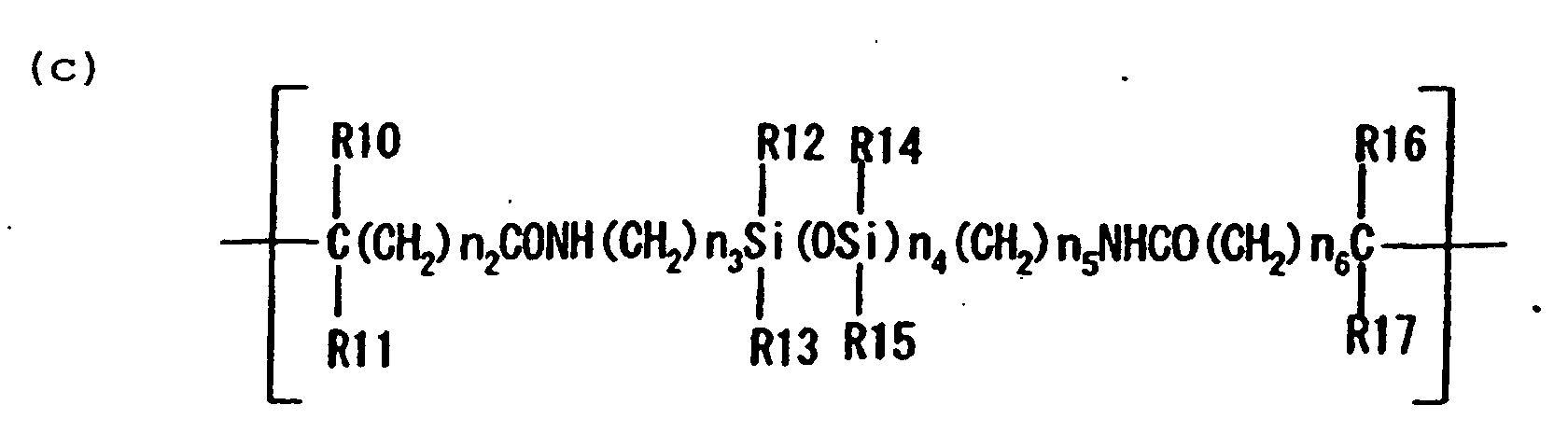
- the first epoxy resin and the second epoxy resin preferably have as a constituting unit, a monomer unit represented by Structural Formula (a) shown below and at least one monomer unit selected from the group consisting of monomers represented by Structural Formulas (b), (c) or (d) independently of each other:
- R1 denotes a hydrogen atom, or a linear or branched alkyl group of 1-3 carbons
- R2 denotes a linear of branched alkylene group of 1-3 carbons
- Z denotes a cyclic aliphatic epoxy group.
- the cyclic aliphatic epoxy group includes epoxycycloalkyl group, specifically epoxycyclohexyl groups represented by the structural formula below, epoxycyclopentyl, epoxycyclobutyl, and like groups.
- R4 denotes a hydrogen atom, or a linear or branched alkyl group of 1-3 carbon atoms
- R5 and R6 independently denote a group selected from methyl and phenyl
- R7-R9 independently denote a hydrogen atom or a linear or branched alkyl group of 1-3 carbons
- n1 denotes an integer of 1-5
- x denotes an integer of 2-100.
- R10, R11, R16, and R17 independently denote a hydrogen atom, a linear or branched alkyl group of 1-3 carbons, or a nitrile group;
- R12-R15 independently denote a hydrogen atom, or a linear or branched alkyl group of 1-3 carbons;
- n2, n3, n5, and n6 independently denote an integer of 1-5;
- n4 denotes an integer of 2-200.
- R18 denotes a hydrogen atom, or a linear or branched alkyl group of 1-3 carbons;
- n7 denotes an integer of 1-5;
- Rf denotes a fluoroalkyl group.
- Rf includes a linear or branched fluoroalkyl group of 6-12 carbons, preferably 8-10 carbons, of which specially preferred are perfluoroalkyl groups.
- first epoxy resin examples include Structural Formulas (A1-1) and (A1-2); and a specific example of the second epoxy resin is shown by Structural Formula (A2-1).
- the first epoxy resin and the second epoxy resin used in the present invention can be obtained by copolymerizing monomers that correspond to the monomer units a-d at a prescribed monomer ratio by a conventional process.
- an epoxy resin containing the monomer units (a) and (b) can be obtained by copolymerizing a monomer represented by Structural Formula (a-1) below and another monomer represented by Structural Formula (b-1) below.
- An epoxy resin containing the above units (a) and (c) can be synthesized by radically polymerizing a monomer represented by Structural Formula (c-1) in the presence of the monomer represented by the above Structural Formula (a-1).
- R19-R22 respectively denote the same groups as R10, R11, R16, and R17.
- the compound represented by Formula (c-1) can be synthesized, for example, by the process described in Japanese Patent Publication No. 2-33053 (Japanese Patent Application Laid-Open No. 61-252230); specifically by reaction of a diamine represented by Formula (c-1-1) below and dihalides represented by Formulas (c-1-2) and (c-1-3) below.
- An epoxy resin containing the units (a) and (d) can be obtained by copolymrizing a monomer represented by the above Formula (a-1) and another monomer represented by Formula (d-1) below.
- the epoxy resin composition of the present invention is mainly composed of the first epoxy resin, the second epoxy resin, and a catalyst, and preferably contains an additional compatibilizer as necessary.
- the compatibilizer is exemplified by the compounds represented by General Formula (1) below and General Formula (2) below.
- the epoxy resin composition of the present invention preferably contains at least one of the compatibilizers represented by the General Formulas (1) and (2). (In the above Formula, p is an integer of 0-2)
- q is an integer of 0-2
- the epoxy resin composition contains a polymerization initiator as a catalyst for curing the composition.
- the catalyst is selected from substances known as epoxy-resin-curing agents.
- the epoxy resin composition of the present invention can be cured by heating the coating formed from the composition with an aromatic or aliphatic amine or an acid anhydride.
- the resin composition is so designed as to be highly reactive to an onium salt of a Lewis acid capable being activated by an active energy ray at a lower temperature. Therefore, by use of the resin composition, a surface of a base material can selectively be treated by photolithography. This is suitable for surface modification, specifically water-repellency treatment, of the surface of an article which does not have sufficient thermal resistance.
- the epoxy resin composition of the present invention may further contain an additional epoxy polymer capable of contributing to the crosslinking reaction by itself as a binder polymer in addition to the aforementioned first epoxy resin:
- the additional epoxy polymer includes acrylic resins produced by copolymerizing acryl monomers having an epoxy group in the side chain, vinyl polymers produced by polymerization of vinyl monomer having a cyclic aliphatic epoxy group in the side chain, polyether polymers having a cyclic aliphatic epoxy group in the side chain (e.g., EHPE 3150 produced by Dicel Chem. Ind.), and so forth.
- the additional polymer is selected in consideration of the properties for use of the resulting composition.
- Such a polymer includes polymer compounds for general-purpose paints such as polymers of bisphenol-type epoxy resins (e.g., "PKHC” and “PKHJ” (trade name, Union Carbide Co.)), poly(ethylene/vinyl acetate) resins, phenol resins, polycarbonate resins, polyester resins, polyamide resins, soluble polyimide resins.
- PKHC bisphenol-type epoxy resins
- PHYJ poly(ethylene/vinyl acetate) resins
- phenol resins phenol resins
- polycarbonate resins phenol resins
- polyester resins polycarbonate resins
- polyamide resins polyamide resins
- soluble polyimide resins soluble polyimide resins
- the epoxy resin composition of the present invention comprises basically
- the curing catalyst (B) is used in an amount of 0.5-7 parts by mass based on 100 parts by mass of the entire epoxy resin composition.
- the blending ratio of the first epoxy resin (A1) to the second epoxy resin (A2) is selected depending on the softening points and glass transition temperatures thereof, generally the ratio A1:A2 ranging from 10:90 to 90:10 (mass ratio), but is not limited thereto. Since these compounds may be less compatible and the onium salt of a Lewis acid, which is the catalyst, is highly polar, the compatibilizer C is advantageously used in many cases.
- the compatibilizer C is preferably used in an amount of 0-80 parts by mass based on 100 parts by mass of the entire epoxy resin.
- the epoxy resin composition of the present invention is useful for surface treatment of articles by heating or active energy ray irradiation.
- the resin composition is dissolved in a solvent such as aromatic hydrocarbons, aliphatic hydrocarbons, esters, ethers, and fluorine-type solvents, and the solution is applied onto a base material surface by a coating/printing method such as roll coating, spin coating, spray coating, die coating (direct coater), screen printing, and gravure coating.
- a coating/printing method such as roll coating, spin coating, spray coating, die coating (direct coater), screen printing, and gravure coating.
- the formed coating is cured by heating or irradiation of active energy rays.
- a suitable active energy ray includes UV rays with a line spectrum containing a large quantity of bright lines in the wavelength range of 200 to 480 nm emitted from a mercury lamp, laser beams, and electron beams.
- the epoxy resin composition of the present invention preferably contains the aforementioned binder component, and formulated to be capable of forming a dry solid coating.
- a surface of an article can readily be treated for water repellency at a prescribed position of the surface by a process similar to photoresist patterning.
- the coating liquid containing the resin composition of the present invention is applied to an article surface by coating or a like method; the solvent is removed to form a dry coating; the coating is irradiated with an active energy ray through a patterned mask, or irradiated in a pattern; and then development treatment is carried out with a solvent capable of dissolving the uncured portion of the coating.
- the surface modification of the present invention as described above enables treatment for water- and/or oil-repellency with sufficient adhesiveness and high hardness of the coating film to modify the base material with high durability, advantageously.
- the article surface is coated with a coating formed from the epoxy resin of the present invention; the coating is cured into a cured coating; and then the cured coating is selectively removed by irradiating the cured coating with excimer laser, or the like.
- a surface of a nozzle of the liquid ejection recording head is treated with the epoxy resin composition of the present invention to modify the surface such that firm adhesion of the ink onto the nozzle surface is prevented and the ink adhering onto the nozzle surface can be wiped off with sufficient releasability by cleaning treatment.
- a cleaning mechanism mounted on the liquid ejection recording apparatus conducts cleaning by wiping the ink with a rubber blade, sucking the ink with a pump, ejecting the ink outside a recording paper sheet, or by a like procedure.
- the column of the ink pushed out by the ejection pressure is not entirely changed into liquid droplets in the liquid droplet forming step, and some of the fine ink droplets not ejected will adhere to the periphery of the nozzle. If the ink droplets not ejected fall off spontaneously, or sucked into the nozzle again, or removed readily, the adverse effects thereof on the ink ejection can be eliminated.
- the epoxy resin composition of the present invention can form a coating which is curable at a relatively low temperature, and is excellent in water- and/or oil-repellency, adhesiveness to a base material, chemical resistance, and abrasion resistance.
- Figs. 1 and 2 show the main portion of an example of the liquid ejection recording head to which the resin composition of the present invention is applicable.
- Fig. 1 is a sectional view taken along the ink flow path.
- Fig. 2 illustrates the ejection orifice face.
- the recording head 13 constructed from a base plate 15 which is equipped with an ejection-energy-generating device and other devices, and a member which is formed from a cured product of a thermosetting resin composition and/or an active energy ray curable resin composition in a prescribed pattern to have at least a flow path and joined to the base plate in lamination.
- the base plate 15 is constituted of a base material 20 made from a material with good radiation properties such as alumina, a heat-accumulating layer 19, a heat-generating resistor layer 18, electrodes 17-1,17-2 and a protection layer 16 laminated in the named order on the base material.
- a base material 20 made from a material with good radiation properties such as alumina, a heat-accumulating layer 19, a heat-generating resistor layer 18, electrodes 17-1,17-2 and a protection layer 16 laminated in the named order on the base material.
- an ejection-energy-generating element formed at the portion of the heat-generating resistor layer 18 where the electrode is not laminated (the portion in the region denoted by the symbol "n") generates heat and the thermal energy is applied to the ink placed thereon.
- the ink 21 is filled into the ejection orifice (nozzle) 22 which is a fine terminal opening of a groove 14.
- flow of electric current through electrodes 17-1,17-2 in correspondence with a recording signal generates heat abruptly in the region "n" to produce a bubble in the ink 21 in contact with it by film-boiling, and the ink 21 is ejected in a form of small liquid droplets 24 through the ejection orifice 22 toward a recording medium 25.
- the cured coating composed of the epoxy resin composition of the present invention is formed as a water- and/or ink-repellant material at least on the periphery of the opening 26 of the ejection orifice of the ejection face 29 (Fig. 2). This prevents the deviation of the direction of liquid droplet ejection caused by adhesion of the liquid droplet on the ejection orifice face. Further, the cured coating composed of the epoxy resin composition of the present invention not only has high adhesiveness to the ejection face 29 but also keeps the water repellency and the adhesiveness, even in the presence of an organic solvent, especially a polar organic solvent in the ink.
- Fig. 3 shows an example of the liquid ejection recording apparatus equipped with the multiple head shown in Fig. 2.
- a blade 61 as a wiping member is held at one end of the blade by a blade-holding member to be a cantilever.
- the blade 61 is placed at a position adjacent to the recording region of the recording head, and, in this example, is held to protrude into the moving path of the recording head.
- a cap 62 is placed at a home position adjacent to the blade 61, and is constituted such that it moves in the direction perpendicular to the moving direction of the recording head to come into contact with the ejection nozzle face to cap the nozzle.
- An ink absorbent 63 is placed at a position adjacent to the blade 61, and is held so as to protrude into the moving path of the recording head 65 in a manner similar to that of the blade 61.
- the blade 61, the cap 62, and the ink absorbent 63 constitute an ejection recovery device 64.
- the blade 61, and the ink absorbent 63 serve to remove off water, dust, and the like from the face of the ink ejection orifice.
- a recording head 65 for recording by a liquid ejection system is constituted to eject a liquid such as an ink by an energy-generating means for the ejection as shown, for example, in Figs. 1 and 2.
- a carriage 66 is provided for carrying and moving the recording head 65.
- the carriage 66 is engaged slidably with a guide rod 67.
- a portion of the carriage 66 is connected (not shown in the drawing) to a belt 69 driven by a motor 68.
- the carriage 66 is made movable along the guide rod 67 to the recording region of the recording head 65 and the adjacent region thereto.
- a paper sheet delivery roller 52 driven by a motor (not shown in the drawing) delivers a recording medium.
- the recording medium is fed to the position opposing to the ejection nozzle face of the recording head with the progress of the recording, and is discharged through a paper-sheet-discharging rollers 53.
- the cap 62 of the ejection-recovery device 64 is positioned out of the moving path of the recording head 65, and the blade 61 is allowed to protrude to the moving path. Thereby, the ejection orifice face of the recording head 65 is wiped. For capping the ejection face of the recording head 65, the cap 62 protrudes toward the moving path of the recording head.
- the recording head 65 When the recording head 65 is moved from the home position to the record-starting position, the cap 62 and the blade 61 are kept at the same position as in the above-mentioned wiping step to wipe the ejection orifice face of the recording head 65 also in this movement.
- the recording head is returned to the home position not only at the completion of the recording and at the time of ejection recovery, but is returned also at predetermined intervals during its movement in the recording region for recording to conduct the wiping operation.
- Color printing with the ink-jet recording apparatus can be conducted by employing a recording head having ejection orifices for colors of cyan, magenta, yellow, and black in juxtaposition in one recording head, or by employing recording heads independently for the respective colors in juxtaposition.
- the color inks may be ejected through one common ejection orifice, or may be ejected through separate ejection orifices for the respective colors concurrently to deposit two or more colors of the liquid droplets on the recording medium simultaneously.
- the surface of the liquid ejection recording head of the present invention is treated with the ink-repellency treatment material containing the epoxy resin compound of the present invention to have the chemical properties as shown later in Examples. Therefore, the ink will adhere less thereto, or adhering ink can be readily removed by cleaning with a cleaning wiper blade. Thus the duration of continuous printing without disruption is remarkably lengthened.
- a photocationic catalyst that releases a Lewis acid by light irradiation is added as a catalyst, whereas for the curing of the coating by heating, a Lewis acid such as boron trifluoride-amine may be added as the catalyst.
- the epoxy resin composition of the present invention is used as a coating liquid in a state of a solution in an organic solvent.
- a thin coating of several ⁇ m thick can be formed by application of the coating liquid with a conventional precision-coating apparatus such as a roll coater, a spin coater, a spray coater, and a die coater (direct coater).
- the above coating liquid is applied on a releasing paper sheet to form a dry film, and the dry film is transferred onto a base material surface to stick thereto by means of a laminator or a like apparatus to form a coating on the base material surface.
- a first method for treating the base material surface in a pattern is conducted by selective irradiation of the coating with an active energy ray through a mask having a prescribed pattern followed by development treatment with a developer to remove the uncured portion of the coating.
- This process is basically similar to a photolithography process.
- the developer should be a solvent or a solvent composition for the resin composition of the present invention.
- the suitable developer includes aromatic solvents, ketones, esters, glycol ethers, and mixtures thereof.
- the coating is preferably heated, or is irradiated with an active energy ray supplementally after the development for complete curing of the coating.
- a second method for treating the base material surface in a pattern is conducted successively through a first step (1) of applying the above coating solution on a base material and drying it to form a coating; a second step (2) of curing the coating by overall irradiation of a polymerization-promoting active energy ray; and a third step (3) of selectively removing the cured film at prescribed portions by irradiation of degrading active energy ray.
- a useful polymerization-promoting active energy ray is an ultraviolet ray rich in the light of wavelength of 250 to 480 m ⁇ m.
- a useful degrading active energy ray includes light of wavelength of 210 m ⁇ m or less, and excimer laser ray.
- the coating is preferably subjected in any of the steps to heat treatment, or to polymerization-promoting active energy ray irradiation.
- the epoxy resin composition of the present invention is useful as a water-repellency imparting agent or a water-repelling paint for application to a member which will brought into contact with a liquid or substance that impairs the adhesiveness of the water-repellent material, such as polar organic solvents, and is also useful for water- and/or ink-repellency treatment of the ejection orifice face of a liquid ejection recording head.
- composition Examples 1 to 4 were respectively dissolved in a mixed solvent composed of ethylene glycol dimethyl ether and toluene (mass ratio, 1:1) as a solvent to prepare solutions at concentrations of 30 to 40%.
- the solutions were respectively applied onto silicon wafer base plates having a 5 ⁇ m-thick thermally oxidated film in a wet thickness of 1-3 ⁇ m by means of a spinner.
- the base plates were dried on a hot plate at 110°C for 5 minutes to remove the solvent.
- the resulting four base plates were respectively irradiated with a UV ray at an integrated dose of 2 J/cm 2 by means of a UV irradiation apparatus employing a high-pressure mercury-vapor lamp, and then heated in a furnace at 150°C for 15 minutes to complete the curing.
- the four base plates were tested as below.
- the measurement was conducted using a contact angle meter (CAX-150, trade name, Kyowa Interface Science Co., Ltd).
- a base plate 41 having elements such as ejection-energy-generating elements (not shown in the drawings) was coated with a positive photoresist (PMER AR-900, trade name, Tokyo Ohka Kogyo Co.) in a coating thickness of 30 ⁇ m by spin coating.
- PMER AR-900 positive photoresist
- the coating was prebaked in an oven at 90°C for 40 minutes to form a resist layer 42.
- the resist layer was irradiated with an active ray through a prescribed mask 43 to make the irradiated portion soluble in a developing solution.
- the resist was developed with a prescribed developing solution to leave a portions 44 corresponding to the ejection orifices (flow paths) to be formed on the base plate.
- the laminated product was left standing at 25°C for 24 hours, and then cured by heating at 100°C for 2 hours.
- the laminated product was immersed in an aqueous 3-mass% sodium hydroxide solution to dissolve and remove the resist pattern 44.
- the resulting product was washed and dried to obtain a liquid ejection recording head.
- the epoxy resin compositions of Examples 1 to 4 were respectively applied, and were cured by UV irradiation at a dose of 8J/cm 2 and heating at 150°C for one hour.
- FluoradTM FC-722 fluoro-coating agent, Sumitomo-3M Co.
- FC-722 fluoro-coating agent, Sumitomo-3M Co.
- the coating formed from the resin composition of the present invention has a large contact angle, and it is kept for a long term. Even after long-term contact with an ink, the print head surface will not cause ink adhesion, resulting in high dot-impact accuracy and high print quality.
- composition Examples 1 and 3 employed in Examples 1 and 3 were respectively applied to polyether sulfone molded plates by a spinner, and dried to obtain a dry thickness of about 2 ⁇ m after solvent evaporation.
- the coated base plates were irradiated with high-pressure mercury lamp light at a total dose of 10 J/cm 2 to cure the coating by polymerization.
- an excimer laser beam of wavelength of 195 m ⁇ m converged to a beam diameter of 5 ⁇ m was applied from above the coating to form a nozzle hole.
- the work for the hole formation was readily conducted without decomposition residue on the edge portion. From the results, the composition of the present invention is particularly suitable for working with a UV laser.
- the present invention provides a resin composition which is useful as a water-repellency imparting agent or a water-repelling paint for application onto the portions that may be brought into contact with a solution or a material containing a component which will impair adhesiveness of the water-repellency imparting agent.
- the present invention provides a resin composition which is suitable for surface modification treatment for keeping the surface condition invariably.
- the present invention further provides an ink-jet recording head and a liquid ejection recording apparatus employing the recording head which has a base plate having been treated with the aforementioned resin composition to keep the nozzle surface unchanged to prevent ink adhesion on the recording head surface even after a long-term contact with an ink, thereby resulting in high dot-impact accuracy and high print quality.
- An embodiment of the invention relates to a novel epoxy resin composition.
- the epoxy resin composition comprises (i) a first epoxy resin having in the molecule thereof at least one water-repellency-imparting group and two or more cyclic aliphatic epoxy groups, and having a number average molecular weight ranging from 8,000 to 22,000 and a polydispersity ranging from 3.5 to 5.0, (ii) a second epoxy resin having in the molecule thereof at least one water-repellency-imparting group and two or more cyclic aliphatic epoxy groups, having a number average molecular weight ranging from 2,500 to 8,000 and a polydispersity ranging from 1.5 to 3.0, and (iii) a cationic polymerization catalyst.
Landscapes
- Chemical & Material Sciences (AREA)
- Polymers & Plastics (AREA)
- Health & Medical Sciences (AREA)
- Chemical Kinetics & Catalysis (AREA)
- Medicinal Chemistry (AREA)
- Organic Chemistry (AREA)
- Manufacturing & Machinery (AREA)
- Engineering & Computer Science (AREA)
- Particle Formation And Scattering Control In Inkjet Printers (AREA)
- Epoxy Resins (AREA)
- Paints Or Removers (AREA)
- Ink Jet Recording Methods And Recording Media Thereof (AREA)
- Inks, Pencil-Leads, Or Crayons (AREA)
Claims (8)
- Epoxyharz-Zusammensetzung, umfassend(i) ein erstes Epoxyharz, das in seinem Molekül mindestens eine Gruppe, die Wasserabweisung verleiht, besitzt, und zwei oder mehr cyclische aliphatische Epoxygruppen, und mit einem Molekulargewicht-Zahlenmittel von 8000 bis 22000, und einer Polydispersität von 3,5 bis 5,0;(ii) ein zweites Epoxyharz, das in seinem Molekül mindestens eine Gruppe, die Wasserabweisung verleiht, besitzt, und zwei oder mehr cyclische aliphatische Epoxygruppen, und mit einem Molekulargewicht-Zahlenmittel von 2500 bis 8000 und einer Polydispersität von 1,5 bis 3,0; und(iii) einem kationischen Polymerisationskatalysator.
- Epoxyharz-Zusammensetzung nach Anspruch 1, wobei die Wasserabweisung-verleihende Gruppe mindestens eine, gewählt aus der Gruppe bestehend aus Perfluoralkylgruppen und Alkylsiloxangruppen ist.
- Epoxyharz-Zusammensetzung nach Anspruch 1 oder 2, wobei das erste Epoxyharz und das zweite Epoxyharz jeweils haben eine Monomereinheit, dargestellt durch die Strukturformel (a), und mindestens eine Monomereinheit, gewählt aus der Gruppe bestehend aus Monomeren, dargestellt durch Strukturformeln (b), (c) oder (d):wobei R1 bezeichnet ein Wasserstoffatom, oder eine lineare oder verzweigte Alkylgruppe mit 1-3 Kohlenstoffatomen; R2 bezeichnet eine lineare oder verzweigte Alkylengruppe mit 1-3 Kohlenstoffatomen; und Z bezeichnet eine cyclische aliphatische Epoxygruppe;
 wobei R4 bezeichnet ein Wasserstoffatom oder eine lineare oder verzweigte Alkylgruppe mit 1-3 Kohlenstoffatomen; R5 und R6 unabhängig voneinander bezeichnen eine Gruppe, gewählt aus der Gruppe bestehend aus Methyl und Phenyl; R7-R9 unabhängig voneinander bezeichnen Wasserstoffatom oder eine lineare oder verzweigte Alkylgruppe mit 1-3 Kohlenstoffatomen; n1 bezeichnet eine ganze Zahl von 1-5; und x bezeichnet eine ganze Zahl von 2-100;
 wobei R10, R11, R16 und R17 unabhängig voneinander bezeichnen ein Wasserstoffatom, eine lineare oder verzweigte Alkylgruppe von 1-3 Kohlenstoffatomen, oder eine Nitrilgruppe; R12-R15 unabhängig bezeichnen ein Wasserstoffatom, oder eine lineare oder verzweigte Alkylgruppe von 1-3 Kohlenstoffatomen; n2, n3, n5 und n6 unabhängig voneinander bezeichnen eine ganze Zahl von 1-5; und n4 bezeichnet eine ganze Zahl von 2-200;
 wobei R18 bezeichnet ein Wasserstoffatom, oder eine lineare oder verzweigte Alkylgruppe von 1-3 Kohlenstoffatomen; n7 bezeichnet eine ganze Zahl von 1-5; und Rf bezeichnet eine Fluoralkylgruppe.
- Epoxyharz-Zusammensetzung nach einem der Ansprüche 1 bis 3, wobei die Epoxyharz-Zusammensetzung zusätzlich enthält, als Kompatibilitätsvermittler, mindestens eine Verbindung, gewählt aus der Gruppe bestehend aus Verbindungen, dargestellt durch die allgemeinen Formeln (1) oder (2):(in der obigen Formel ist p eine ganze Zahl von 0-2)
 (in der obigen Formel ist q eine ganze Zahl von 0-2;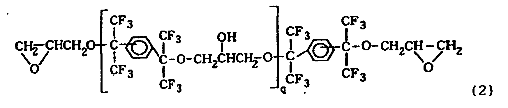

- Verfahren zum Behandeln einer Oberfläche eines Gegenstandes, umfassend die Schritte(i) Erzeugen einer Beschichtung der Epoxyharz-Zusammensetzung nach einem der Ansprüche 1 bis 4 auf einer Oberfläche eines Gegenstandes;(ii) selektives Bestrahlen der Beschichtung mit einem wirksamen Energiestrahl; und(iii) Entfernen des Abschnitts der Beschichtung, der nicht mit dem wirksamen Energiestrahl bestrahlt worden ist, durch Verwendung einer Flüssigkeit, die fähig ist, den Abschnitt der Beschichtung, der nicht mit dem wirksamen Energiestrahl bestrahlt worden ist, aufzulösen.
- Verfahren zum Behandeln einer Oberfläche eines Gegenstandes, umfassend die Schritte(i) Erzeugen einer Beschichtung der Epoxyharz-Zusammensetzung nach einem der Ansprüche 1 bis 4 auf einer Oberfläche eines Gegenstandes;(ii) Polymerisieren der Beschichtung und Härten der Beschichtung; und(iii) selektives Entfernen der Beschichtung, welche im Schritt (ii) gehärtet worden ist.
- Flüssigkeitsausstoßungsaufzeichnungskopf mit einer Ausstoßungsöffnung zum Ausstoßen einer Flüssigkeit, wobei die Peripherie der Ausstoßungsöffnung mit einem gehärteten Film der Epoxyharz-Zusammensetzung nach einem der Ansprüche 1 bis 4 bedeckt ist.
- Flüssigkeitsausstoßungsaufzeichnungsvorrichtung, umfassend den Flüssigkeitsausstoßungsaufzeichnungskopf nach Anspruch 7.
Applications Claiming Priority (2)
| Application Number | Priority Date | Filing Date | Title |
|---|---|---|---|
| JP2002008441 | 2002-01-17 | ||
| JP2002008441 | 2002-01-17 |
Publications (2)
| Publication Number | Publication Date |
|---|---|
| EP1329472A1 EP1329472A1 (de) | 2003-07-23 |
| EP1329472B1 true EP1329472B1 (de) | 2005-10-05 |
Family
ID=19191422
Family Applications (1)
| Application Number | Title | Priority Date | Filing Date |
|---|---|---|---|
| EP03000885A Expired - Lifetime EP1329472B1 (de) | 2002-01-17 | 2003-01-15 | Epoxidharzzusammensetzung, Verfahren zur Oberflächenmodifizierung, Tintenstrahlaufzeichnungskopf und Tintenstrahlaufzeichnungsapparat |
Country Status (6)
| Country | Link |
|---|---|
| US (2) | US7074273B2 (de) |
| EP (1) | EP1329472B1 (de) |
| KR (1) | KR100541903B1 (de) |
| CN (1) | CN1208388C (de) |
| AT (1) | ATE305947T1 (de) |
| DE (1) | DE60301736T2 (de) |
Families Citing this family (23)
| Publication number | Priority date | Publication date | Assignee | Title |
|---|---|---|---|---|
| US6992117B2 (en) * | 2002-01-17 | 2006-01-31 | Canon Kabushiki Kaisha | Epoxy resin composition, surface treatment method, liquid-jet recording head and liquid-jet recording apparatus |
| JP2003277651A (ja) * | 2002-03-20 | 2003-10-02 | Brother Ind Ltd | インクジェット記録用水性インク及びインクジェット記録方法 |
| US20080116663A1 (en) * | 2004-04-26 | 2008-05-22 | Kaj Gyr | Pivoting ski binding |
| WO2007148822A1 (en) * | 2006-06-23 | 2007-12-27 | Canon Kabushiki Kaisha | Polyfunctional epoxy compound, epoxy resin, cationic photopolymerizable epoxy resin composition, micro structured member, producing method therefor and liquid discharge head |
| KR101320780B1 (ko) | 2006-10-30 | 2013-10-22 | 소니 주식회사 | 액체 토출형 기록 헤드 및 액체 토출 장치 |
| US8042908B2 (en) * | 2007-07-27 | 2011-10-25 | Hewlett-Packard Development Company, L.P. | Fluid ejector device |
| US20090031922A1 (en) * | 2007-07-30 | 2009-02-05 | Sukanya Rengaswamy | Ink composition and method for forming the same |
| US11786036B2 (en) | 2008-06-27 | 2023-10-17 | Ssw Advanced Technologies, Llc | Spill containing refrigerator shelf assembly |
| US8286561B2 (en) | 2008-06-27 | 2012-10-16 | Ssw Holding Company, Inc. | Spill containing refrigerator shelf assembly |
| AU2009302329B2 (en) | 2008-10-07 | 2015-10-29 | Ssw Advanced Technologies, Llc | Spill resistant surfaces having hydrophobic and oleophobic borders |
| US8455176B2 (en) * | 2008-11-12 | 2013-06-04 | Az Electronic Materials Usa Corp. | Coating composition |
| CN102516497B (zh) * | 2008-12-19 | 2013-08-28 | 比亚迪股份有限公司 | 含氟树脂及其制备方法以及保形涂料和印刷线路板 |
| ES2613885T3 (es) | 2009-11-04 | 2017-05-26 | Ssw Holding Company, Inc. | Superficies de aparatos de cocción que tienen un patrón de confinamiento de salpicaduras y procedimientos de fabricación de las mismas |
| JP5858441B2 (ja) | 2010-03-15 | 2016-02-10 | ロス テクノロジー コーポレーション.Ross Technology Corporation | プランジャーおよび疎水性表面を得るための方法 |
| JP2014512417A (ja) | 2011-02-21 | 2014-05-22 | ロス テクノロジー コーポレーション. | 低voc結合剤系を含む超疎水性および疎油性被覆物 |
| DE102011085428A1 (de) | 2011-10-28 | 2013-05-02 | Schott Ag | Einlegeboden |
| EP2791255B1 (de) | 2011-12-15 | 2017-11-01 | Ross Technology Corporation | Zusammensetzung und beschichtung für superhydrophobe leistung |
| EP2864430A4 (de) | 2012-06-25 | 2016-04-13 | Ross Technology Corp | Elastomerische beschichtungen mit hydrophoben und/oder oleophoben eigenschaften |
| JP6410460B2 (ja) * | 2014-04-23 | 2018-10-24 | キヤノン株式会社 | 組成物、該組成物を用いた膜の製造方法、および液体吐出ヘッドの製造方法 |
| JP6632225B2 (ja) * | 2015-06-05 | 2020-01-22 | キヤノン株式会社 | 吐出口面の撥水処理方法 |
| US10850512B2 (en) | 2018-02-23 | 2020-12-01 | Canon Kabushiki Kaisha | Ink jet recording head and method of manufacturing same |
| JP7098350B2 (ja) | 2018-02-28 | 2022-07-11 | キヤノン株式会社 | 接着シートを用いたインクジェット記録ヘッド及び製造方法 |
| US20260042917A1 (en) * | 2024-08-06 | 2026-02-12 | Canon Kabushiki Kaisha | Photosensitive resin composition, liquid-repellent anti-fouling film, and inkjet recording head |
Family Cites Families (17)
| Publication number | Priority date | Publication date | Assignee | Title |
|---|---|---|---|---|
| JPH0233053B2 (ja) | 1985-04-30 | 1990-07-25 | Osaka City | Azokiganjuhorishirokisanamido |
| IT1199770B (it) | 1986-12-16 | 1988-12-30 | Ausimont Spa | Resine epossidiche ottenute mediante coreticolazione di prepolimeri epossidici fluorurati e prepolimeri epossidici non fluorurati |
| US4954580A (en) | 1987-12-01 | 1990-09-04 | Ciba-Geigy Corporation | Epoxysiloxanes |
| JP2593922B2 (ja) | 1988-07-30 | 1997-03-26 | キヤノン株式会社 | インクジエット記録ヘッド |
| EP0368320B1 (de) | 1988-11-10 | 1997-10-08 | Dai Nippon Insatsu Kabushiki Kaisha | Bildempfangsschicht für Übertragung durch Wärme |
| JPH08301954A (ja) | 1995-04-28 | 1996-11-19 | Toray Dow Corning Silicone Co Ltd | 硬化性剥離剤組成物 |
| EP0779337B1 (de) | 1995-06-13 | 2001-10-24 | Canon Kabushiki Kaisha | In lösungsmittel hochlösliches fluor enthaltende epoxidharzzusammensetzung |
| US6126922A (en) * | 1995-11-17 | 2000-10-03 | 3M Innovative Properties Company | Fluorid-releasing compositions and compositions with improved rheology |
| US5998073A (en) * | 1997-03-10 | 1999-12-07 | Ricoh Company, Ltd. | Dry toner for electrophotography |
| JPH11316472A (ja) * | 1998-03-03 | 1999-11-16 | Mitsubishi Chemical Corp | 静電荷像現像用トナー |
| US6472129B2 (en) | 1998-03-10 | 2002-10-29 | Canon Kabushiki Kaisha | Fluorine-containing epoxy resin composition, and surface modification process, ink jet recording head and ink jet recording apparatus making use of the same |
| US6139920A (en) * | 1998-12-21 | 2000-10-31 | Xerox Corporation | Photoresist compositions |
| CN1166989C (zh) * | 1999-04-02 | 2004-09-15 | 三洋化成工业株式会社 | 干式调色剂 |
| EP1085031B1 (de) | 1999-09-20 | 2004-11-17 | Canon Kabushiki Kaisha | Alkylsiloxanenthaltende Epoxidharzzusammensetzung, Verwendung als Oberflächenmodifizierungsmittel, Tintenstrahldruckkopf und Flüssigkeitsstrahlaufzeichnungsgerät |
| EP1229395B1 (de) * | 2001-01-31 | 2006-01-11 | Ricoh Company, Ltd. | Trockentoner zur Entwicklung elektrostatischer Bilder |
| US6750290B2 (en) | 2001-04-19 | 2004-06-15 | Canon Kabushiki Kaisha | Epoxy resin composition, method of improving surface of substrate, ink jet recording head and ink jet recording apparatus |
| US6992117B2 (en) | 2002-01-17 | 2006-01-31 | Canon Kabushiki Kaisha | Epoxy resin composition, surface treatment method, liquid-jet recording head and liquid-jet recording apparatus |
-
2003
- 2003-01-10 CN CNB031002773A patent/CN1208388C/zh not_active Expired - Fee Related
- 2003-01-14 US US10/341,373 patent/US7074273B2/en not_active Expired - Fee Related
- 2003-01-15 EP EP03000885A patent/EP1329472B1/de not_active Expired - Lifetime
- 2003-01-15 AT AT03000885T patent/ATE305947T1/de not_active IP Right Cessation
- 2003-01-15 DE DE60301736T patent/DE60301736T2/de not_active Expired - Lifetime
- 2003-01-16 KR KR1020030002993A patent/KR100541903B1/ko not_active Expired - Fee Related
-
2005
- 2005-12-01 US US11/290,539 patent/US7566758B2/en not_active Expired - Fee Related
Also Published As
| Publication number | Publication date |
|---|---|
| US7566758B2 (en) | 2009-07-28 |
| US20030170401A1 (en) | 2003-09-11 |
| CN1208388C (zh) | 2005-06-29 |
| DE60301736T2 (de) | 2006-07-06 |
| KR100541903B1 (ko) | 2006-01-10 |
| US7074273B2 (en) | 2006-07-11 |
| ATE305947T1 (de) | 2005-10-15 |
| US20060089466A1 (en) | 2006-04-27 |
| KR20030063164A (ko) | 2003-07-28 |
| EP1329472A1 (de) | 2003-07-23 |
| DE60301736D1 (de) | 2006-02-16 |
| CN1432600A (zh) | 2003-07-30 |
Similar Documents
| Publication | Publication Date | Title |
|---|---|---|
| EP1329472B1 (de) | Epoxidharzzusammensetzung, Verfahren zur Oberflächenmodifizierung, Tintenstrahlaufzeichnungskopf und Tintenstrahlaufzeichnungsapparat | |
| KR100626782B1 (ko) | 에폭시 수지 조성물, 표면 처리 방법, 액체 분사 기록헤드 및 액체 분사 기록 장치 | |
| EP1783153B1 (de) | Oberflächenabänderungsprozess mit Fluor enthaltenden Epoxidharz | |
| US6869541B2 (en) | Epoxy resin composition, surface treating method, ink-jet recording head, and ink-jet recording apparatus | |
| EP1085031B1 (de) | Alkylsiloxanenthaltende Epoxidharzzusammensetzung, Verwendung als Oberflächenmodifizierungsmittel, Tintenstrahldruckkopf und Flüssigkeitsstrahlaufzeichnungsgerät | |
| EP0942025B1 (de) | Tintenstrahlaufzeichnungskopf und Aufzeichnungsapparat mit einer fluorierten Epoxydharzzusammensetzung | |
| EP0942026A2 (de) | Fluor enthaltende Epoxidharzzusammensetzung, Verfahren zur Oberflächenmodifizierung ,Tintenstrahlaufzeichnungskopf und diesen Kopf tragenderAufzeichnungsapparat | |
| KR100564851B1 (ko) | 에폭시 수지 조성물, 표면 처리 방법, 액체 분사 기록헤드 및 액체 분사 기록 장치 | |
| JP4174124B2 (ja) | 含フッ素エポキシ樹脂組成物を用いた表面改質方法、インクジェット記録ヘッド、インクジェット記録装置 | |
| JP4175620B2 (ja) | エポキシ樹脂組成物、及び液体噴射記録ヘッド | |
| JPH11335440A (ja) | 含フッ素エポキシ樹脂組成物及びこれを用いた表面改質方法、インクジェット記録ヘッド、インクジェット記録装置 | |
| JP4174329B2 (ja) | エポキシ樹脂組成物、及び液体噴射記録ヘッド | |
| JP2003277472A (ja) | エポキシ樹脂組成物 | |
| JP4006346B2 (ja) | エポキシ樹脂組成物、これを用いた物品の表面の選択的処理方法及びインクジェット記録ヘッド | |
| JP2001158818A (ja) | 含アルキルシロキサンエポキシ樹脂組成物及びそれを用いた表面改質方法、インクジェット記録へッド、液体噴射記録装置 |
Legal Events
| Date | Code | Title | Description |
|---|---|---|---|
| PUAI | Public reference made under article 153(3) epc to a published international application that has entered the european phase |
Free format text: ORIGINAL CODE: 0009012 |
|
| AK | Designated contracting states |
Designated state(s): AT BE BG CH CY CZ DE DK EE ES FI FR GB GR HU IE IT LI LU MC NL PT SE SI SK TR |
|
| AX | Request for extension of the european patent |
Extension state: AL LT LV MK RO |
|
| 17P | Request for examination filed |
Effective date: 20031208 |
|
| AKX | Designation fees paid |
Designated state(s): AT BE BG CH CY CZ DE DK EE ES FI FR GB GR HU IE IT LI LU MC NL PT SE SI SK TR |
|
| 17Q | First examination report despatched |
Effective date: 20040527 |
|
| GRAP | Despatch of communication of intention to grant a patent |
Free format text: ORIGINAL CODE: EPIDOSNIGR1 |
|
| GRAS | Grant fee paid |
Free format text: ORIGINAL CODE: EPIDOSNIGR3 |
|
| GRAA | (expected) grant |
Free format text: ORIGINAL CODE: 0009210 |
|
| AK | Designated contracting states |
Kind code of ref document: B1 Designated state(s): AT BE BG CH CY CZ DE DK EE ES FI FR GB GR HU IE IT LI LU MC NL PT SE SI SK TR |
|
| PG25 | Lapsed in a contracting state [announced via postgrant information from national office to epo] |
Ref country code: NL Free format text: LAPSE BECAUSE OF FAILURE TO SUBMIT A TRANSLATION OF THE DESCRIPTION OR TO PAY THE FEE WITHIN THE PRESCRIBED TIME-LIMIT Effective date: 20051005 Ref country code: FI Free format text: LAPSE BECAUSE OF FAILURE TO SUBMIT A TRANSLATION OF THE DESCRIPTION OR TO PAY THE FEE WITHIN THE PRESCRIBED TIME-LIMIT Effective date: 20051005 Ref country code: BE Free format text: LAPSE BECAUSE OF FAILURE TO SUBMIT A TRANSLATION OF THE DESCRIPTION OR TO PAY THE FEE WITHIN THE PRESCRIBED TIME-LIMIT Effective date: 20051005 Ref country code: AT Free format text: LAPSE BECAUSE OF FAILURE TO SUBMIT A TRANSLATION OF THE DESCRIPTION OR TO PAY THE FEE WITHIN THE PRESCRIBED TIME-LIMIT Effective date: 20051005 Ref country code: SK Free format text: LAPSE BECAUSE OF FAILURE TO SUBMIT A TRANSLATION OF THE DESCRIPTION OR TO PAY THE FEE WITHIN THE PRESCRIBED TIME-LIMIT Effective date: 20051005 Ref country code: CH Free format text: LAPSE BECAUSE OF FAILURE TO SUBMIT A TRANSLATION OF THE DESCRIPTION OR TO PAY THE FEE WITHIN THE PRESCRIBED TIME-LIMIT Effective date: 20051005 Ref country code: SI Free format text: LAPSE BECAUSE OF FAILURE TO SUBMIT A TRANSLATION OF THE DESCRIPTION OR TO PAY THE FEE WITHIN THE PRESCRIBED TIME-LIMIT Effective date: 20051005 Ref country code: CZ Free format text: LAPSE BECAUSE OF FAILURE TO SUBMIT A TRANSLATION OF THE DESCRIPTION OR TO PAY THE FEE WITHIN THE PRESCRIBED TIME-LIMIT Effective date: 20051005 Ref country code: LI Free format text: LAPSE BECAUSE OF FAILURE TO SUBMIT A TRANSLATION OF THE DESCRIPTION OR TO PAY THE FEE WITHIN THE PRESCRIBED TIME-LIMIT Effective date: 20051005 |
|
| REG | Reference to a national code |
Ref country code: GB Ref legal event code: FG4D |
|
| REG | Reference to a national code |
Ref country code: CH Ref legal event code: EP |
|
| REG | Reference to a national code |
Ref country code: IE Ref legal event code: FG4D |
|
| PG25 | Lapsed in a contracting state [announced via postgrant information from national office to epo] |
Ref country code: SE Free format text: LAPSE BECAUSE OF FAILURE TO SUBMIT A TRANSLATION OF THE DESCRIPTION OR TO PAY THE FEE WITHIN THE PRESCRIBED TIME-LIMIT Effective date: 20060105 Ref country code: GR Free format text: LAPSE BECAUSE OF FAILURE TO SUBMIT A TRANSLATION OF THE DESCRIPTION OR TO PAY THE FEE WITHIN THE PRESCRIBED TIME-LIMIT Effective date: 20060105 Ref country code: BG Free format text: LAPSE BECAUSE OF FAILURE TO SUBMIT A TRANSLATION OF THE DESCRIPTION OR TO PAY THE FEE WITHIN THE PRESCRIBED TIME-LIMIT Effective date: 20060105 Ref country code: DK Free format text: LAPSE BECAUSE OF FAILURE TO SUBMIT A TRANSLATION OF THE DESCRIPTION OR TO PAY THE FEE WITHIN THE PRESCRIBED TIME-LIMIT Effective date: 20060105 |
|
| PG25 | Lapsed in a contracting state [announced via postgrant information from national office to epo] |
Ref country code: ES Free format text: LAPSE BECAUSE OF FAILURE TO SUBMIT A TRANSLATION OF THE DESCRIPTION OR TO PAY THE FEE WITHIN THE PRESCRIBED TIME-LIMIT Effective date: 20060116 Ref country code: IE Free format text: LAPSE BECAUSE OF NON-PAYMENT OF DUE FEES Effective date: 20060116 |
|
| PG25 | Lapsed in a contracting state [announced via postgrant information from national office to epo] |
Ref country code: MC Free format text: LAPSE BECAUSE OF NON-PAYMENT OF DUE FEES Effective date: 20060131 Ref country code: LU Free format text: LAPSE BECAUSE OF NON-PAYMENT OF DUE FEES Effective date: 20060131 |
|
| REF | Corresponds to: |
Ref document number: 60301736 Country of ref document: DE Date of ref document: 20060216 Kind code of ref document: P |
|
| NLV1 | Nl: lapsed or annulled due to failure to fulfill the requirements of art. 29p and 29m of the patents act | ||
| PG25 | Lapsed in a contracting state [announced via postgrant information from national office to epo] |
Ref country code: PT Free format text: LAPSE BECAUSE OF FAILURE TO SUBMIT A TRANSLATION OF THE DESCRIPTION OR TO PAY THE FEE WITHIN THE PRESCRIBED TIME-LIMIT Effective date: 20060306 |
|
| PG25 | Lapsed in a contracting state [announced via postgrant information from national office to epo] |
Ref country code: HU Free format text: LAPSE BECAUSE OF FAILURE TO SUBMIT A TRANSLATION OF THE DESCRIPTION OR TO PAY THE FEE WITHIN THE PRESCRIBED TIME-LIMIT Effective date: 20060406 |
|
| REG | Reference to a national code |
Ref country code: CH Ref legal event code: PL |
|
| ET | Fr: translation filed | ||
| PLBE | No opposition filed within time limit |
Free format text: ORIGINAL CODE: 0009261 |
|
| STAA | Information on the status of an ep patent application or granted ep patent |
Free format text: STATUS: NO OPPOSITION FILED WITHIN TIME LIMIT |
|
| 26N | No opposition filed |
Effective date: 20060706 |
|
| REG | Reference to a national code |
Ref country code: IE Ref legal event code: MM4A |
|
| PG25 | Lapsed in a contracting state [announced via postgrant information from national office to epo] |
Ref country code: EE Free format text: LAPSE BECAUSE OF FAILURE TO SUBMIT A TRANSLATION OF THE DESCRIPTION OR TO PAY THE FEE WITHIN THE PRESCRIBED TIME-LIMIT Effective date: 20051005 |
|
| PG25 | Lapsed in a contracting state [announced via postgrant information from national office to epo] |
Ref country code: TR Free format text: LAPSE BECAUSE OF FAILURE TO SUBMIT A TRANSLATION OF THE DESCRIPTION OR TO PAY THE FEE WITHIN THE PRESCRIBED TIME-LIMIT Effective date: 20051005 |
|
| PG25 | Lapsed in a contracting state [announced via postgrant information from national office to epo] |
Ref country code: CY Free format text: LAPSE BECAUSE OF FAILURE TO SUBMIT A TRANSLATION OF THE DESCRIPTION OR TO PAY THE FEE WITHIN THE PRESCRIBED TIME-LIMIT Effective date: 20051005 |
|
| REG | Reference to a national code |
Ref country code: FR Ref legal event code: PLFP Year of fee payment: 14 |
|
| PGFP | Annual fee paid to national office [announced via postgrant information from national office to epo] |
Ref country code: DE Payment date: 20160131 Year of fee payment: 14 Ref country code: IT Payment date: 20160105 Year of fee payment: 14 |
|
| PGFP | Annual fee paid to national office [announced via postgrant information from national office to epo] |
Ref country code: FR Payment date: 20160126 Year of fee payment: 14 Ref country code: GB Payment date: 20160127 Year of fee payment: 14 |
|
| REG | Reference to a national code |
Ref country code: DE Ref legal event code: R119 Ref document number: 60301736 Country of ref document: DE |
|
| GBPC | Gb: european patent ceased through non-payment of renewal fee |
Effective date: 20170115 |
|
| REG | Reference to a national code |
Ref country code: FR Ref legal event code: ST Effective date: 20170929 |
|
| PG25 | Lapsed in a contracting state [announced via postgrant information from national office to epo] |
Ref country code: FR Free format text: LAPSE BECAUSE OF NON-PAYMENT OF DUE FEES Effective date: 20170131 |
|
| PG25 | Lapsed in a contracting state [announced via postgrant information from national office to epo] |
Ref country code: DE Free format text: LAPSE BECAUSE OF NON-PAYMENT OF DUE FEES Effective date: 20170801 Ref country code: GB Free format text: LAPSE BECAUSE OF NON-PAYMENT OF DUE FEES Effective date: 20170115 |
|
| PG25 | Lapsed in a contracting state [announced via postgrant information from national office to epo] |
Ref country code: IT Free format text: LAPSE BECAUSE OF NON-PAYMENT OF DUE FEES Effective date: 20170115 |