EP1329494A2 - Gasogène à co-courant - Google Patents
Gasogène à co-courant Download PDFInfo
- Publication number
- EP1329494A2 EP1329494A2 EP03405016A EP03405016A EP1329494A2 EP 1329494 A2 EP1329494 A2 EP 1329494A2 EP 03405016 A EP03405016 A EP 03405016A EP 03405016 A EP03405016 A EP 03405016A EP 1329494 A2 EP1329494 A2 EP 1329494A2
- Authority
- EP
- European Patent Office
- Prior art keywords
- gasifiers
- screw
- vertical
- fact
- coupled
- Prior art date
- Legal status (The legal status is an assumption and is not a legal conclusion. Google has not performed a legal analysis and makes no representation as to the accuracy of the status listed.)
- Granted
Links
Images


Classifications
-
- C—CHEMISTRY; METALLURGY
- C10—PETROLEUM, GAS OR COKE INDUSTRIES; TECHNICAL GASES CONTAINING CARBON MONOXIDE; FUELS; LUBRICANTS; PEAT
- C10J—PRODUCTION OF PRODUCER GAS, WATER-GAS, SYNTHESIS GAS FROM SOLID CARBONACEOUS MATERIAL, OR MIXTURES CONTAINING THESE GASES; CARBURETTING AIR OR OTHER GASES
- C10J3/00—Production of combustible gases containing carbon monoxide from solid carbonaceous fuels
- C10J3/02—Fixed-bed gasification of lump fuel
- C10J3/20—Apparatus; Plants
- C10J3/34—Grates; Mechanical ash-removing devices
-
- C—CHEMISTRY; METALLURGY
- C10—PETROLEUM, GAS OR COKE INDUSTRIES; TECHNICAL GASES CONTAINING CARBON MONOXIDE; FUELS; LUBRICANTS; PEAT
- C10J—PRODUCTION OF PRODUCER GAS, WATER-GAS, SYNTHESIS GAS FROM SOLID CARBONACEOUS MATERIAL, OR MIXTURES CONTAINING THESE GASES; CARBURETTING AIR OR OTHER GASES
- C10J3/00—Production of combustible gases containing carbon monoxide from solid carbonaceous fuels
- C10J3/02—Fixed-bed gasification of lump fuel
- C10J3/20—Apparatus; Plants
- C10J3/30—Fuel charging devices
-
- C—CHEMISTRY; METALLURGY
- C10—PETROLEUM, GAS OR COKE INDUSTRIES; TECHNICAL GASES CONTAINING CARBON MONOXIDE; FUELS; LUBRICANTS; PEAT
- C10J—PRODUCTION OF PRODUCER GAS, WATER-GAS, SYNTHESIS GAS FROM SOLID CARBONACEOUS MATERIAL, OR MIXTURES CONTAINING THESE GASES; CARBURETTING AIR OR OTHER GASES
- C10J2200/00—Details of gasification apparatus
- C10J2200/09—Mechanical details of gasifiers not otherwise provided for, e.g. sealing means
-
- C—CHEMISTRY; METALLURGY
- C10—PETROLEUM, GAS OR COKE INDUSTRIES; TECHNICAL GASES CONTAINING CARBON MONOXIDE; FUELS; LUBRICANTS; PEAT
- C10J—PRODUCTION OF PRODUCER GAS, WATER-GAS, SYNTHESIS GAS FROM SOLID CARBONACEOUS MATERIAL, OR MIXTURES CONTAINING THESE GASES; CARBURETTING AIR OR OTHER GASES
- C10J2200/00—Details of gasification apparatus
- C10J2200/15—Details of feeding means
- C10J2200/158—Screws
-
- C—CHEMISTRY; METALLURGY
- C10—PETROLEUM, GAS OR COKE INDUSTRIES; TECHNICAL GASES CONTAINING CARBON MONOXIDE; FUELS; LUBRICANTS; PEAT
- C10J—PRODUCTION OF PRODUCER GAS, WATER-GAS, SYNTHESIS GAS FROM SOLID CARBONACEOUS MATERIAL, OR MIXTURES CONTAINING THESE GASES; CARBURETTING AIR OR OTHER GASES
- C10J2300/00—Details of gasification processes
- C10J2300/09—Details of the feed, e.g. feeding of spent catalyst, inert gas or halogens
- C10J2300/0913—Carbonaceous raw material
- C10J2300/0916—Biomass
- C10J2300/092—Wood, cellulose
-
- C—CHEMISTRY; METALLURGY
- C10—PETROLEUM, GAS OR COKE INDUSTRIES; TECHNICAL GASES CONTAINING CARBON MONOXIDE; FUELS; LUBRICANTS; PEAT
- C10J—PRODUCTION OF PRODUCER GAS, WATER-GAS, SYNTHESIS GAS FROM SOLID CARBONACEOUS MATERIAL, OR MIXTURES CONTAINING THESE GASES; CARBURETTING AIR OR OTHER GASES
- C10J2300/00—Details of gasification processes
- C10J2300/09—Details of the feed, e.g. feeding of spent catalyst, inert gas or halogens
- C10J2300/0953—Gasifying agents
- C10J2300/0956—Air or oxygen enriched air
-
- C—CHEMISTRY; METALLURGY
- C10—PETROLEUM, GAS OR COKE INDUSTRIES; TECHNICAL GASES CONTAINING CARBON MONOXIDE; FUELS; LUBRICANTS; PEAT
- C10J—PRODUCTION OF PRODUCER GAS, WATER-GAS, SYNTHESIS GAS FROM SOLID CARBONACEOUS MATERIAL, OR MIXTURES CONTAINING THESE GASES; CARBURETTING AIR OR OTHER GASES
- C10J2300/00—Details of gasification processes
- C10J2300/18—Details of the gasification process, e.g. loops, autothermal operation
- C10J2300/1807—Recycle loops, e.g. gas, solids, heating medium, water
Definitions
- the present invention relates to a co-current gasifier as described in the prologue of claim 1.
- co-current gasifiers of which the most efficient are the gasifiers at a hearth, also called combustion chamber, of form circular obtained by a narrowing of the fuel supply chamber, in which the fuel moves from top to bottom by gravity (this is, for the accuracy of the gasifiers mounted on vehicles during the forties and supplied with wood, type IMBERT) then made it possible to verify a principle of great importance, i.e. co-current gasification ensures the production of a gas in which tar, dioxins and furans are absent, only at the provided that a certain ratio between the surface of the hearth and the average particle size fuel is respected.
- the dimensions of the hearth must be adapted to the grain size. average fuel to be gasified. Materials of small particle size, such as for example plant residues, household or industrial, prepared for the gasification, (dried, shredded, homogenized to obtain a fuel whose properties are regular) therefore require, according to the aforementioned condition, that the fireplace dimensions are also limited, thereby limiting the power of such gasifiers.
- the present invention proposes to eliminate these drawbacks of the technology of known co-current gasifiers, so as to be able to produce gasifiers of medium and high power (of the order of at least 1 MWel) which guarantee the production of a gas without tars, dioxins and furans, in quantity and in quality, respectively constant regarding these perfect parameters, and to create among other the ideal conditions for the use of syngas for energy production electric supplied by internal combustion engines.
- Another object of the invention is to prepare the ideal conditions for manufacturing co-current gasifiers of variable power, as required, by providing element modules which can be mechanically coupled and / or activated as required.
- the pos. 1 of the same fig. represents a worm for feeding material fresh. It transports the material coming from a feed hopper (better visible in fig. 3) to bring it to the start of the turns of a vertical worm 2 which transports this material from the bottom to the top.
- the worm 2 is well heard in a cylindrical housing 3, possibly provided with all the elements known to each person skilled in the art, elements intended to promote correct transport material from bottom to top.
- the rotation shaft 4 of the screw 2 can be hollow, as shown in fig. 1, for a reason which will be explained further.
- the shaft 4 of the screw 2 is driven by a gear 5 and a helical gear 6.
- the material supply screw 1, the cylindrical housing 3, the vertical shaft 4 of the vertical screw 2, as well as the gears 5 and 6 are supported, respectively fixed, in, respectively, a frame 7, with the necessary housings, which can be equipped, as in the case rotating shafts, linear or rotary ball bearings.
- a hearth is created, according to the invention, understood by that, that in this zone, in the shape of a full disc, all the material which cross member is forced to pass into a combustion zone, where it is brought to the temperature of at least 1200 ° C for a sufficient time.
- a hearth is created, according to the invention, understood by that, that in this zone, in the shape of a full disc, all the material which cross member is forced to pass into a combustion zone, where it is brought to the temperature of at least 1200 ° C for a sufficient time.
- outside air is supplied by means of a fan (not indicated) and a tube supply 8, to a circular chamber 9 surrounding the upper edge of the housing 2 at a point above the highest point of the turns of the vertical screw 2, where the material transported to gasify forms a compact column.
- the diameter of the screw vertical 2 does not exceed a certain dimension, mainly depending on the average particle size of the material to be gasified and preferably situated for a optimal functioning of the gasifier according to the present invention and for the combustion of wood chips of approximate dimensions of cm, from 100 to 200 mm and more, the supply of air only from the outside may be sufficient to ensure the necessary and regular combustion over the entire surface of the fireplace.
- a primary combustion air supply to the lower part of the hearth i.e. at the lower central part of the disc which forms the hearth: to achieve this variant of the combustion air supply, it it will suffice to provide that the shaft 4 of the vertical screw is, as already shown in FIG. 1, a hollow shaft supplied from below, by means of the supply tube 10, with air which passes through the shaft on which the gear 5 is fixed, a shaft which is therefore hollow.
- the combustion air supply conditions in the hearths are particularly difficult (due for example to a particle size relatively small material to be gasified compared to the diameter of the hearth, respectively of the vertical screw 2, or at a higher flow rate of the material to gasify etc, ...) it may be useful, and may be necessary, to provide air oxidizer both from the outside of the hearth and from its bottom, i.e. its outer edge, ie at its lower central surface via the tubes 8 and 10. It is important that the material passes through the hearth, as a compact column which will be heated throughout its mass to a temperature above 1200 ° C for enough time.
- a gasification chamber 11 disposed at the above the hearth, the function of which is described in detail in document EP-0565935 and that a device 12 for circulation of the material which has already passed through is provided the hearth and the gasification chamber 11.
- a circulation device 12 which can assume various forms and which will be described in more detail, in its constructive part and of operation, in a preferred embodiment, when the variants shown in fig. from 2 to 5, embodiment which allows to carry over gasifying material in fresh material which has not yet been carbonated, another time through the foyer.
- Figures 2, 3 and 4 show precisely the possibility of coupling four gas generators and, on this subject, it should be mentioned that two gasifiers put together, one against the other, as can be seen in the section of fig. 2, constitute a module of ideal base for the combination of such multiple gasifiers.
- the right part of fig. 2 is perfectly equal and opposite to that on the right.
- the elements shown in fig. 2 are therefore exactly the same as those described in fig. 1 and are no longer described separately.
- the advantage of combining two gas generators coupled to form a ideal basic module is that the material feed auger 1 and the helical gear 6 of the supply of the vertical screws 2 and 2 ', both horizontal and parallel to each other, can be used optimally to power the two coupled gasifiers, which considerably simplifies the construction of the device.
- the screw rotation device 2 and 2 ′ comprises, in the variant of FIG.
- the feed screw 1 for fresh material - analogously as described for the shaft helical gears 6 - is arranged in the vertical plane of symmetry of each ideal basic module of two coupled gasifiers and that it even extends along the entire length of the gasifier, feeding collectively all the gas generators constituting the said device.
- Figs. 1 to 4 we see a particularly preferred form of the circulation 12, 12 'of the material which has already passed through the foyer and the gasification 11, 11 '.
- a device comprises a horizontal worm discharge 19, 19 'for each gasifier, arranged above the gasification 11, 11 ', respectively between the gasification chambers 11, 11' and the expansion chamber 14.
- the worm 19,19 'evacuation of each gasifier, including the axis is perpendicular to that of the feed screw 1, pushes the pyrolyzed material (coal) and / or not yet completely gasified outside of the gasification 11, 11 'of the gasifier and returns it to the zone where the screw is located endless 2 or 2 '. In this way the material to be circulated is mixed with the fresh material fed by feed screw 1 and passes through a hearth of another gasifier.
- fig. 2 is shown an additional detail, concerning the module formed by the coupling of two gasifiers, which shows how the air primary oxidizer which passes through the tube 10 can be preheated, and cool the said screw before entering the trees 4, 4 ′ of the so-called gas generators.
- the air is pulsed by a fan (not shown) through the tube 20 on which the screws are fixed endless 19, 19 'evacuation of the two gasifiers making up the ideal basic module. Passing through the tube 20 the combustion air is heated by conduction by the gas which goes up to the expansion chamber 14 and licks the tube 20.
- the horizontal endless discharge screws 19, 19 ′ of the two coupled gas generators, making up an ideal basic module move the material in circulation as shown in figs. 2 and 3.
- the screws endless horizontal evacuation19, 19 'of the two coupled gasifiers forming a ideal basic module when they rotate in the normal direction, move the material circulation, towards the center of the module, in a vertical channel, through which the circulating material descends on the fresh material feed screw 1.
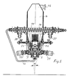
- Fig. 5 shows a later variant of two gasifiers coupled to form a ideal basic module, the advantage of which is to reduce the bulk, especially in the lower part of the gasifier.
- the axes of the two screws 25,26 two gasifiers coupled to form an ideal basic module form between them an angle ⁇ between 0 and 20 °.
- the vertical screws 2, 2 ' are defined as "essentially" vertical, but a slight tilt does cannot be excluded from the scope of the invention.
- the gasifier according to the invention also offers the advantage when it is combined with other gasifiers to form a higher power gasifier, if the essentially vertical screws 2, 2 'etc are to be actuated individually, it is possible, in a device composed of several gasifiers, to maintain in function only those who are really useful at each moment, to adapt the apparatus for the energy productions actually necessary, respectively for the availability of equipment to carbonate. For this purpose, it is sufficient to provide that, in a solution like the one shown in figs. 2 to 4, gears 5, 5 'etc, screws 2, 2 'etc, either connected with the respective shafts by a coupling mechanical or any other system, which allows them to be released when you want to stop the operation of the corresponding gasifier. Another possibility, shown in embodiment of fig.
Landscapes
- Chemical & Material Sciences (AREA)
- Engineering & Computer Science (AREA)
- Combustion & Propulsion (AREA)
- Oil, Petroleum & Natural Gas (AREA)
- Organic Chemistry (AREA)
- Mechanical Engineering (AREA)
- Processing Of Solid Wastes (AREA)
- Feeding, Discharge, Calcimining, Fusing, And Gas-Generation Devices (AREA)
- Control Of Electrical Variables (AREA)
- Emergency Protection Circuit Devices (AREA)
- Vertical, Hearth, Or Arc Furnaces (AREA)
Abstract
L'avantage de cette forme de réalisation, comparée à l'Etat de la Technique qui prévoit l'utilisation d'un foyer annulaire, réside dans le fait qu'elle élimine le risque de formation de passages préférentiels et de canaux dans la zone de gazéification qui provoquent des irrégularités de combustion et de gazéification, et qu'elle adapte l'épaisseur de la zone de combustion à la granulométrie moyenne du matériel. En outre le gazogène selon la présente invention se prête à l'assemblage de deux gazogènes, pour former ainsi des appareils de gazéification de puissances élevées (5 kWél. et plus) dotés cependant de grandes variations d'utilisation et d'adaptation optimale, grâce à la possibilité de faire fonctionner séparément les gazogènes individuels, adaptant ainsi la production d'énergie à la disponibilité momentanée du combustible.
Description
- avantages : température du gaz relativement basse teneur faible de poudres fines de charbon dans le gaz coûts de fabrication réduits.
- inconvénients : teneur élevée de goudrons, dioxines et furanes dans le gaz, avec comme conséquence, des coûts élevés des installations de son nettoyage et risques de pollutions de l'environnement.
- avantages : le gaz produit, si le gazogène est bien conçu, ne contient pratiquement pas de goudrons, de dioxines et de furanes et le nettoyage du gaz produit est beaucoup plus simple et moins onéreux que pour le traitement du gaz des gazogènes à contre courant, traitement nécessaire pour réduire les effets nocifs pour l'environnement.
- inconvénients : leurs dimensions sont limitées et ne permettent pas de réaliser des installations de très grandes puissances. coûts de fabrication plus élevés teneur de poudre de charbon également plus importante.
- la fig. 1 la vue en coupe d'un gazogène selon l'invention montrant schématiquement tous ses éléments essentiels .
- la fig. 2 la vue en coupe d'un appareil de gazéification dans lequel quatre gazogènes à co-courant selon l'invention sont accouplés en deux modules pour former un appareil représenté schématiquement.
- la fig. 3 l'appareil de gazéification selon la fig. 2 dans une section schématique perpendiculaire à celle de la fig.2 à travers un axe de rotation d'un des gazogènes représentés.
- la fig. 4 la vue en plan de l'appareil de gazéification selon les fig. 2 et 3 dans une section schématique dans un plan légèrement au dessus du foyer de chacun des gazogènes.
- la fig. 5 une vue en coupe semblable à celle de la fig. 2, d'une variante d'appareil de gazéification dans lequel deux gazogènes selon l'invention accouplés sont réciproquement inclinés pour former un V.
- 1.
- Vis d'alimentation du matériel
- 2, 2'
- Vis sans fin verticale
- 3.
- Logement cylindrique
- 4.
- Arbre
- 5, 5'
- Engrenage
- 6.
- Engrenage hélicoïdal horizontal
- 7.
- Logement
- 8.
- Tube d'alimentation
- 9.
- Chambre circulaire
- 10.
- Tube d'alimentation
- 11.
- Chambre de gazéification
- 12.
- Dispositif de circulation
- 13.
- Résistance électrique
- 14.
- Chambre de détente
- 15.
- Tube de sortie
- 16.
- Matériel réfractaire
- 19.19'
- Vis d'évacuation
- 20.
- Tube
- 21.
- Ouverture
- 22.
- Trémie
- 23.
- Tube
- 24.
- Tube incliné
- 25.
- Vis sans fin
- 26.
- Vis sans fin
- 27.
- Tube
- 28.
- Tube
- 29, 29'
- Moteur
Claims (14)
- Gazogène à co-courant avec une vis sans fin (1) d'alimentation du matériel frais à gazéifier, avec une vis sans fin (2) essentiellement verticale transportant le matériel à gazéifier du bas vers le haut, avec un foyer disposé dans la partie supérieure de la sortie de la vis sans fin (2), avec une chambre de gazéification (11) disposée au dessus du foyer, ainsi qu'un dispositif de circulation (12) du matériel qui a déjà passé au travers du foyer et la chambre de gazéification (11) et qui n'est pas complètement gazéifié, qui reporte ce matériel dans le matériel frais à gazéifier, pour le faire passer une autre fois au travers du foyer,
caractérisé par le fait que
le foyer est constitué par la section circulaire totale de la vis essentiellement verticale (2) transportant le matériel et que l'air comburant primaire arrive au foyer de l'extérieur de sa délimitation circulaire et/ou au centre du dit foyer. - Gazogène à co-courant selon la revendication 1,
caractérisé par le fait que
au moins deux gazogènes sont reliés l'un contre le flanc de l'autre et sont équipés d'un dispositif de rotation collectif des vis essentiellement verticale (2, 2'). - Gazogène à co-courant selon la revendication 2,
caractérisé par le fait que
deux gazogènes accouplés constituent un module de base idéal qui peut être lui même accouplé à plusieurs modules semblables pour former ainsi un appareil de gazéification formé d'un nombre quelconque de gazogènes. - Gazogène à co-courant selon la revendication 3,
caractérisé par le fait que
les vis verticales de tous les gazogènes qui constituent l'appareil de gazéification sont entraínées par un dispositif tournant collectif. - Gazogène à co-courant selon une des revendications de 2 à 4,
caractérisé par le fait que,
le dispositif d'entraínement tournant est constitué par un arbre horizontal (6), disposé dans le plan de symétrie de chaque couple de gazogènes, équipé d'un engrenage hélicoïdal (6) pour chaque couple de gazogènes et qui entraíne un engrenage fixé sur l'arbre vertical de chacune des vis (2, 2') essentiellement verticales de chaque gazogène. - Gazogène à co-courant selon la revendication (1),
caractérisé par le fait que
la vis d'alimentation (1) du matériel frais à gazéifier est disposée horizontalement et est reliée à la partie inférieure de la vis essentiellement verticale (2, 2'), dans le but de pousser le matériel à gazéifier à la base des spires de la vis essentiellement verticale (2, 2'). - Gazogène à co-courant selon la revendication 6 et l'une des revendications de 2 à 5,
caractérisé par le fait que
la vis d'alimentation (1) du matériel frais est disposée dans le plan vertical de symétrie de chaque module de base idéal de deux gazogènes accouplés et se prolonge le long de toute la longueur de l'appareil de gazéification, alimentant collectivement tous les gazogènes qui constituent l'appareil lui même. - Gazogène à co-courant selon la revendication 1,
caractérisé par le fait que
le dispositif de circulation (12, 12') du matériel déjà passé au travers du foyer et la chambre de gazéification comprend une vis sans fin horizontale d'évacuation qui pousse le matériel pas encore complètement gazéifié à l'extérieur de la chambre de gazéification du gazogène et le fait retourner dans la zone d'action d'une vis essentiellement verticale (2, 2') transportant le matériel du bas vers le haut. - Gazogène à co-courant selon la revendication 8 et une des revendications de 2 à 5,
caractérisé par le fait que
les vis horizontales d'évacuation (19, 19') des deux gazogènes accouplés formant un module de base idéal sont coaxiales et alimentent le matériel en circulation réciproquement en sens opposés. - Gazogène à co-courant selon la revendication 9,
caractérisé par le fait que
les vis sans fin horizontales d'évacuation (19, 19') des deux gazogènes accouplés formant un module de base idéal déplacent le matériel en circulation, dans leur sens de rotation normal, vers le centre du module, où une ouverture (21) est prévue pour le conduire dans la zone d'action d'une vis d'alimentation du matériel frais (1) au travers d'un canal vertical. - Gazogène à co-courant selon la revendication 10,
caractérisé par le fait que
si on inverse le sens de rotation des vis horizontales d'évacuation (19, 19') des deux gazogènes accouplés formant un module de base idéal, ces dernières déplacent le matériel à éliminer, matériel incombustible, vers l'extérieur de l'appareil de gazéification, d'où ce matériel est éloigné. - Gazogène à co-courant selon les revendications de 2 à 5,
caractérisé par le fait que
sont accouplés au moins deux modules de base idéaux, de préférence quatre ou plus modules de base idéaux. - Gazogène à co-courant selon la revendication 1,
caractérisé par le fait que
le diamètre de la vis essentiellement verticale transportant le matériel à gazéifier du bas vers le haut est compris de 100 à 200 mm et plus. - Gazogène à co-courant selon une des revendications de 2 à 5,
caractérisé par le fait que
les axes des deux vis (25, 25 ') essentiellement verticales des deux gazogènes accouplés pour former un module de base idéal forme entre eux un angle α de 0 à 20°.
Applications Claiming Priority (2)
| Application Number | Priority Date | Filing Date | Title |
|---|---|---|---|
| CH752002 | 2002-01-18 | ||
| CH752002 | 2002-01-18 |
Publications (3)
| Publication Number | Publication Date |
|---|---|
| EP1329494A2 true EP1329494A2 (fr) | 2003-07-23 |
| EP1329494A3 EP1329494A3 (fr) | 2004-03-17 |
| EP1329494B1 EP1329494B1 (fr) | 2007-09-12 |
Family
ID=4326419
Family Applications (1)
| Application Number | Title | Priority Date | Filing Date |
|---|---|---|---|
| EP03405016A Expired - Lifetime EP1329494B1 (fr) | 2002-01-18 | 2003-01-17 | Gasogène à co-courant |
Country Status (3)
| Country | Link |
|---|---|
| EP (1) | EP1329494B1 (fr) |
| AT (1) | ATE373068T1 (fr) |
| DE (1) | DE60316206T2 (fr) |
Cited By (2)
| Publication number | Priority date | Publication date | Assignee | Title |
|---|---|---|---|---|
| NL1035829C2 (nl) * | 2008-08-15 | 2009-08-06 | Jacobus Anna Joseph Hubertus Mohr | Inrichting voor het produceren van houtgas als alternatieve brandstofvoorziening voor verbrandingsmotoren (houtgasgenerator). |
| CN111978995A (zh) * | 2020-09-03 | 2020-11-24 | 辽宁科技大学 | 一种催化热解烟气循环的垃圾热解气化炉及其工作方法 |
Family Cites Families (5)
| Publication number | Priority date | Publication date | Assignee | Title |
|---|---|---|---|---|
| FR2520375A1 (fr) * | 1982-01-26 | 1983-07-29 | Iakovenko Marinitch Vladimir | Appareil modulaire de gazeification des matieres combustibles |
| DE8328140U1 (de) * | 1983-09-28 | 1991-04-25 | Michel-Kim, Herwig, 1000 Berlin | Reaktorvorrichtung zur Erzeugung von Generatorgas aus brennbaren Abfallprodukten |
| DE3509263A1 (de) * | 1985-03-12 | 1986-10-16 | Silica Gel GmbH Adsorptions-Technik, Apparatebau, 1000 Berlin | Verfahren und vorrichtung zur regelung der brennstoffzufuhr eines unterschubvergasers |
| DE3732867A1 (de) * | 1987-09-25 | 1989-04-06 | Michel Kim Herwig | Verfahren und vorrichtung zum erzeugen von generatorgas und aktivierter kohle aus festen brennstoffen |
| CH685244A5 (it) * | 1992-04-10 | 1995-05-15 | Poretti & Gaggini S A | Gasogeno ad equicorrente. |
-
2003
- 2003-01-17 AT AT03405016T patent/ATE373068T1/de not_active IP Right Cessation
- 2003-01-17 EP EP03405016A patent/EP1329494B1/fr not_active Expired - Lifetime
- 2003-01-17 DE DE60316206T patent/DE60316206T2/de not_active Expired - Lifetime
Cited By (2)
| Publication number | Priority date | Publication date | Assignee | Title |
|---|---|---|---|---|
| NL1035829C2 (nl) * | 2008-08-15 | 2009-08-06 | Jacobus Anna Joseph Hubertus Mohr | Inrichting voor het produceren van houtgas als alternatieve brandstofvoorziening voor verbrandingsmotoren (houtgasgenerator). |
| CN111978995A (zh) * | 2020-09-03 | 2020-11-24 | 辽宁科技大学 | 一种催化热解烟气循环的垃圾热解气化炉及其工作方法 |
Also Published As
| Publication number | Publication date |
|---|---|
| EP1329494A3 (fr) | 2004-03-17 |
| DE60316206T2 (de) | 2008-06-05 |
| ATE373068T1 (de) | 2007-09-15 |
| EP1329494B1 (fr) | 2007-09-12 |
| DE60316206D1 (de) | 2007-10-25 |
Similar Documents
| Publication | Publication Date | Title |
|---|---|---|
| CH621571A5 (fr) | ||
| EP0565935B1 (fr) | Gazogène à co-courant | |
| FR2964114A1 (fr) | Systeme et procede de gazeification de produits de la biomasse | |
| FR2656326A1 (fr) | Procedes, dispositifs et fours tournants pour fabriquer en continu du charbon de bois riche en carbone. | |
| EP1329494B1 (fr) | Gasogène à co-courant | |
| EP2218300A2 (fr) | Dispositif de traitement thermique de solides divises | |
| EP0045256A2 (fr) | Procédé et installation de gazéification de matières d'origine végétale | |
| EP2723832B1 (fr) | Gazeifieur de combustible solide carbone | |
| EP0165224A1 (fr) | Equipement de chauffe directe | |
| EP1970424A1 (fr) | Dispositif et procédé de pyrolyse d'une biomasse | |
| BE1027557B1 (fr) | Systeme de torrefaction | |
| FR2472139A1 (fr) | Generateur de gaz chauds et son utilisation pour fournir des calories a un appareil utilisateur tel que four, sechoir, chaudiere | |
| FR2463360A1 (fr) | Installation de combustion a combustibles solides | |
| FR2517413A1 (fr) | Generateur de chaleur fonctionnant avec un combustible particulaire | |
| FR2671166A1 (fr) | Chaufferie specialement concue pour la combustion de bois dechiquete. | |
| FR2505350A1 (fr) | Gazeificateurs de combustibles solides a lit fixe et a tirage inverse | |
| EP3885651B1 (fr) | Systeme de grille de decendrage rotative pour foyer d'une installation de combustion ou de gazeification | |
| FR2983203A1 (fr) | Installation de traitement comprenant un reacteur de thermolyse | |
| FR2468070A1 (fr) | Generateur de gaz de combustion a haute temperature | |
| WO2013034608A1 (fr) | Gazeifieur de combustible solide carbone | |
| FR2961582A1 (fr) | Bruleur anti-machefer | |
| FR2930981A1 (fr) | Chaudiere pour combustible solide, liquide ou pulverulent | |
| FR2508140A1 (fr) | Installation de chauffage a combustible solide par exemple pulverulent, comportant un dispositif de fond de foyer ajoure | |
| EP2273191A1 (fr) | Chaudière pour combustible solide, liquide ou pulvérulent | |
| FR3047300A1 (fr) | Procede de gazeification et dispositifs permettant de le mettre en oeuvre |
Legal Events
| Date | Code | Title | Description |
|---|---|---|---|
| PUAI | Public reference made under article 153(3) epc to a published international application that has entered the european phase |
Free format text: ORIGINAL CODE: 0009012 |
|
| AK | Designated contracting states |
Designated state(s): AT BE BG CH CY CZ DE DK EE ES FI FR GB GR HU IE IT LI LU MC NL PT SE SI SK TR |
|
| AX | Request for extension of the european patent |
Extension state: AL LT LV MK RO |
|
| RIN1 | Information on inventor provided before grant (corrected) |
Inventor name: L'INVENTEUR A RENONCE AE SA DESIGNATION. |
|
| PUAL | Search report despatched |
Free format text: ORIGINAL CODE: 0009013 |
|
| AK | Designated contracting states |
Kind code of ref document: A3 Designated state(s): AT BE BG CH CY CZ DE DK EE ES FI FR GB GR HU IE IT LI LU MC NL PT SE SI SK TR |
|
| AX | Request for extension of the european patent |
Extension state: AL LT LV MK RO |
|
| RIC1 | Information provided on ipc code assigned before grant |
Ipc: 7C 10J 3/30 A Ipc: 7C 10J 3/34 B |
|
| 17P | Request for examination filed |
Effective date: 20040916 |
|
| AKX | Designation fees paid |
Designated state(s): AT BE BG CH CY CZ DE DK EE ES FI FR GB GR HU IE IT LI LU MC NL PT SE SI SK TR |
|
| RAP1 | Party data changed (applicant data changed or rights of an application transferred) |
Owner name: GAGGINI, CARLO |
|
| GRAP | Despatch of communication of intention to grant a patent |
Free format text: ORIGINAL CODE: EPIDOSNIGR1 |
|
| GRAS | Grant fee paid |
Free format text: ORIGINAL CODE: EPIDOSNIGR3 |
|
| GRAA | (expected) grant |
Free format text: ORIGINAL CODE: 0009210 |
|
| AK | Designated contracting states |
Kind code of ref document: B1 Designated state(s): AT BE BG CH CY CZ DE DK EE ES FI FR GB GR HU IE IT LI LU MC NL PT SE SI SK TR |
|
| REG | Reference to a national code |
Ref country code: GB Ref legal event code: FG4D Free format text: NOT ENGLISH |
|
| REG | Reference to a national code |
Ref country code: CH Ref legal event code: EP |
|
| REF | Corresponds to: |
Ref document number: 60316206 Country of ref document: DE Date of ref document: 20071025 Kind code of ref document: P |
|
| REG | Reference to a national code |
Ref country code: IE Ref legal event code: FG4D Free format text: LANGUAGE OF EP DOCUMENT: FRENCH |
|
| PG25 | Lapsed in a contracting state [announced via postgrant information from national office to epo] |
Ref country code: FI Free format text: LAPSE BECAUSE OF FAILURE TO SUBMIT A TRANSLATION OF THE DESCRIPTION OR TO PAY THE FEE WITHIN THE PRESCRIBED TIME-LIMIT Effective date: 20070912 |
|
| NLV1 | Nl: lapsed or annulled due to failure to fulfill the requirements of art. 29p and 29m of the patents act | ||
| GBV | Gb: ep patent (uk) treated as always having been void in accordance with gb section 77(7)/1977 [no translation filed] | ||
| PG25 | Lapsed in a contracting state [announced via postgrant information from national office to epo] |
Ref country code: NL Free format text: LAPSE BECAUSE OF FAILURE TO SUBMIT A TRANSLATION OF THE DESCRIPTION OR TO PAY THE FEE WITHIN THE PRESCRIBED TIME-LIMIT Effective date: 20070912 Ref country code: ES Free format text: LAPSE BECAUSE OF FAILURE TO SUBMIT A TRANSLATION OF THE DESCRIPTION OR TO PAY THE FEE WITHIN THE PRESCRIBED TIME-LIMIT Effective date: 20071223 |
|
| REG | Reference to a national code |
Ref country code: IE Ref legal event code: FD4D |
|
| PG25 | Lapsed in a contracting state [announced via postgrant information from national office to epo] |
Ref country code: PT Free format text: LAPSE BECAUSE OF FAILURE TO SUBMIT A TRANSLATION OF THE DESCRIPTION OR TO PAY THE FEE WITHIN THE PRESCRIBED TIME-LIMIT Effective date: 20080212 Ref country code: SK Free format text: LAPSE BECAUSE OF FAILURE TO SUBMIT A TRANSLATION OF THE DESCRIPTION OR TO PAY THE FEE WITHIN THE PRESCRIBED TIME-LIMIT Effective date: 20070912 Ref country code: CZ Free format text: LAPSE BECAUSE OF FAILURE TO SUBMIT A TRANSLATION OF THE DESCRIPTION OR TO PAY THE FEE WITHIN THE PRESCRIBED TIME-LIMIT Effective date: 20070912 Ref country code: GB Free format text: LAPSE BECAUSE OF FAILURE TO SUBMIT A TRANSLATION OF THE DESCRIPTION OR TO PAY THE FEE WITHIN THE PRESCRIBED TIME-LIMIT Effective date: 20070912 |
|
| PG25 | Lapsed in a contracting state [announced via postgrant information from national office to epo] |
Ref country code: SE Free format text: LAPSE BECAUSE OF FAILURE TO SUBMIT A TRANSLATION OF THE DESCRIPTION OR TO PAY THE FEE WITHIN THE PRESCRIBED TIME-LIMIT Effective date: 20071212 |
|
| PLBE | No opposition filed within time limit |
Free format text: ORIGINAL CODE: 0009261 |
|
| STAA | Information on the status of an ep patent application or granted ep patent |
Free format text: STATUS: NO OPPOSITION FILED WITHIN TIME LIMIT |
|
| BERE | Be: lapsed |
Owner name: GAGGINI, CARLO Effective date: 20080131 |
|
| PG25 | Lapsed in a contracting state [announced via postgrant information from national office to epo] |
Ref country code: DK Free format text: LAPSE BECAUSE OF FAILURE TO SUBMIT A TRANSLATION OF THE DESCRIPTION OR TO PAY THE FEE WITHIN THE PRESCRIBED TIME-LIMIT Effective date: 20070912 |
|
| 26N | No opposition filed |
Effective date: 20080613 |
|
| PG25 | Lapsed in a contracting state [announced via postgrant information from national office to epo] |
Ref country code: MC Free format text: LAPSE BECAUSE OF NON-PAYMENT OF DUE FEES Effective date: 20080131 |
|
| PGFP | Annual fee paid to national office [announced via postgrant information from national office to epo] |
Ref country code: AT Payment date: 20080414 Year of fee payment: 6 |
|
| PG25 | Lapsed in a contracting state [announced via postgrant information from national office to epo] |
Ref country code: IE Free format text: LAPSE BECAUSE OF FAILURE TO SUBMIT A TRANSLATION OF THE DESCRIPTION OR TO PAY THE FEE WITHIN THE PRESCRIBED TIME-LIMIT Effective date: 20070912 |
|
| PG25 | Lapsed in a contracting state [announced via postgrant information from national office to epo] |
Ref country code: EE Free format text: LAPSE BECAUSE OF FAILURE TO SUBMIT A TRANSLATION OF THE DESCRIPTION OR TO PAY THE FEE WITHIN THE PRESCRIBED TIME-LIMIT Effective date: 20070912 |
|
| PG25 | Lapsed in a contracting state [announced via postgrant information from national office to epo] |
Ref country code: BE Free format text: LAPSE BECAUSE OF NON-PAYMENT OF DUE FEES Effective date: 20080131 |
|
| PG25 | Lapsed in a contracting state [announced via postgrant information from national office to epo] |
Ref country code: SI Free format text: LAPSE BECAUSE OF FAILURE TO SUBMIT A TRANSLATION OF THE DESCRIPTION OR TO PAY THE FEE WITHIN THE PRESCRIBED TIME-LIMIT Effective date: 20070912 |
|
| PG25 | Lapsed in a contracting state [announced via postgrant information from national office to epo] |
Ref country code: CY Free format text: LAPSE BECAUSE OF FAILURE TO SUBMIT A TRANSLATION OF THE DESCRIPTION OR TO PAY THE FEE WITHIN THE PRESCRIBED TIME-LIMIT Effective date: 20070912 |
|
| PG25 | Lapsed in a contracting state [announced via postgrant information from national office to epo] |
Ref country code: BG Free format text: LAPSE BECAUSE OF FAILURE TO SUBMIT A TRANSLATION OF THE DESCRIPTION OR TO PAY THE FEE WITHIN THE PRESCRIBED TIME-LIMIT Effective date: 20071212 |
|
| PG25 | Lapsed in a contracting state [announced via postgrant information from national office to epo] |
Ref country code: AT Free format text: LAPSE BECAUSE OF NON-PAYMENT OF DUE FEES Effective date: 20090117 |
|
| PGFP | Annual fee paid to national office [announced via postgrant information from national office to epo] |
Ref country code: FR Payment date: 20100210 Year of fee payment: 8 Ref country code: IT Payment date: 20100122 Year of fee payment: 8 |
|
| PG25 | Lapsed in a contracting state [announced via postgrant information from national office to epo] |
Ref country code: LU Free format text: LAPSE BECAUSE OF NON-PAYMENT OF DUE FEES Effective date: 20080117 Ref country code: HU Free format text: LAPSE BECAUSE OF FAILURE TO SUBMIT A TRANSLATION OF THE DESCRIPTION OR TO PAY THE FEE WITHIN THE PRESCRIBED TIME-LIMIT Effective date: 20080313 |
|
| PG25 | Lapsed in a contracting state [announced via postgrant information from national office to epo] |
Ref country code: TR Free format text: LAPSE BECAUSE OF FAILURE TO SUBMIT A TRANSLATION OF THE DESCRIPTION OR TO PAY THE FEE WITHIN THE PRESCRIBED TIME-LIMIT Effective date: 20070912 |
|
| PGFP | Annual fee paid to national office [announced via postgrant information from national office to epo] |
Ref country code: DE Payment date: 20100331 Year of fee payment: 8 |
|
| PGFP | Annual fee paid to national office [announced via postgrant information from national office to epo] |
Ref country code: CH Payment date: 20100421 Year of fee payment: 8 |
|
| PG25 | Lapsed in a contracting state [announced via postgrant information from national office to epo] |
Ref country code: GR Free format text: LAPSE BECAUSE OF NON-PAYMENT OF DUE FEES Effective date: 20080131 |
|
| REG | Reference to a national code |
Ref country code: CH Ref legal event code: PL |
|
| REG | Reference to a national code |
Ref country code: FR Ref legal event code: ST Effective date: 20110930 |
|
| PG25 | Lapsed in a contracting state [announced via postgrant information from national office to epo] |
Ref country code: LI Free format text: LAPSE BECAUSE OF NON-PAYMENT OF DUE FEES Effective date: 20110131 Ref country code: CH Free format text: LAPSE BECAUSE OF NON-PAYMENT OF DUE FEES Effective date: 20110131 Ref country code: FR Free format text: LAPSE BECAUSE OF NON-PAYMENT OF DUE FEES Effective date: 20110131 |
|
| REG | Reference to a national code |
Ref country code: DE Ref legal event code: R119 Ref document number: 60316206 Country of ref document: DE Effective date: 20110802 |
|
| PG25 | Lapsed in a contracting state [announced via postgrant information from national office to epo] |
Ref country code: IT Free format text: LAPSE BECAUSE OF NON-PAYMENT OF DUE FEES Effective date: 20110117 |
|
| PG25 | Lapsed in a contracting state [announced via postgrant information from national office to epo] |
Ref country code: DE Free format text: LAPSE BECAUSE OF NON-PAYMENT OF DUE FEES Effective date: 20110802 |