EP1329574B1 - Verriegelungsvorrichtung - Google Patents
Verriegelungsvorrichtung Download PDFInfo
- Publication number
- EP1329574B1 EP1329574B1 EP02425015A EP02425015A EP1329574B1 EP 1329574 B1 EP1329574 B1 EP 1329574B1 EP 02425015 A EP02425015 A EP 02425015A EP 02425015 A EP02425015 A EP 02425015A EP 1329574 B1 EP1329574 B1 EP 1329574B1
- Authority
- EP
- European Patent Office
- Prior art keywords
- locking means
- rotating body
- condition
- locking
- transmission
- Prior art date
- Legal status (The legal status is an assumption and is not a legal conclusion. Google has not performed a legal analysis and makes no representation as to the accuracy of the status listed.)
- Expired - Lifetime
Links
- 230000005540 biological transmission Effects 0.000 claims abstract description 34
- 230000033001 locomotion Effects 0.000 claims abstract description 24
- 238000006073 displacement reaction Methods 0.000 claims abstract description 11
- 239000002184 metal Substances 0.000 claims description 13
- 230000008878 coupling Effects 0.000 claims description 4
- 238000010168 coupling process Methods 0.000 claims description 4
- 238000005859 coupling reaction Methods 0.000 claims description 4
- 230000013011 mating Effects 0.000 claims 1
- 238000010276 construction Methods 0.000 description 4
- 238000003780 insertion Methods 0.000 description 2
- 230000037431 insertion Effects 0.000 description 2
- 238000004519 manufacturing process Methods 0.000 description 2
- 239000000463 material Substances 0.000 description 2
- 239000007769 metal material Substances 0.000 description 2
- 238000000605 extraction Methods 0.000 description 1
- 238000000465 moulding Methods 0.000 description 1
- 238000004804 winding Methods 0.000 description 1
Images



Classifications
-
- E—FIXED CONSTRUCTIONS
- E05—LOCKS; KEYS; WINDOW OR DOOR FITTINGS; SAFES
- E05C—BOLTS OR FASTENING DEVICES FOR WINGS, SPECIALLY FOR DOORS OR WINDOWS
- E05C9/00—Arrangements of simultaneously actuated bolts or other securing devices at well-separated positions on the same wing
- E05C9/04—Arrangements of simultaneously actuated bolts or other securing devices at well-separated positions on the same wing with two sliding bars moved in opposite directions when fastening or unfastening
-
- E—FIXED CONSTRUCTIONS
- E05—LOCKS; KEYS; WINDOW OR DOOR FITTINGS; SAFES
- E05B—LOCKS; ACCESSORIES THEREFOR; HANDCUFFS
- E05B1/00—Knobs or handles for wings; Knobs, handles, or press buttons for locks or latches on wings
- E05B1/0092—Moving otherwise than only rectilinearly or only rotatively
-
- E—FIXED CONSTRUCTIONS
- E05—LOCKS; KEYS; WINDOW OR DOOR FITTINGS; SAFES
- E05B—LOCKS; ACCESSORIES THEREFOR; HANDCUFFS
- E05B13/00—Devices preventing the key or the handle or both from being used
- E05B13/10—Devices preventing the key or the handle or both from being used formed by a lock arranged in the handle
-
- E—FIXED CONSTRUCTIONS
- E05—LOCKS; KEYS; WINDOW OR DOOR FITTINGS; SAFES
- E05B—LOCKS; ACCESSORIES THEREFOR; HANDCUFFS
- E05B15/00—Other details of locks; Parts for engagement by bolts of fastening devices
- E05B15/16—Use of special materials for parts of locks
- E05B15/1635—Use of special materials for parts of locks of plastics materials
- E05B2015/1642—Use of special materials for parts of locks of plastics materials for the whole lock
Definitions
- the present invention relates to a locking device.
- a locking device is preferably adapted for used on doors or panels of wardrobes, metal cabinets or lockers. It is however apparent that application of the locking device to other typologies of doors or panels is also possible depending on current requirements.
- the movement means operatively interposed between the lever and the closure means can be consisting in a rack-and-pinion mechanism, wherein a toothed wheel meshes with two sliding and partially toothed rods or, alternatively, by a rotating sash whereupon two tangentially opposed rods are articulated at opposite radial locations.
- a rotation from the rest position of the handle involves a rotatory movement of a pinion gear rigidly associated with the handle which meshes with corresponding slots present in a closing bar involving a translation of said bar parallel to the panel plane.
- the present invention aims at providing a locking device equipped with a new and different movement-transmitting system.
- a locking device has been generally identified by reference numeral 1.
- Such a device will be preferably usable on panels or doors of metal material to enable locking/unlocking of the cabinet door.
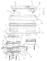
- the device consists of a support structure 2 (in turn made up of several different components), a driving element 3 or handle associated with the support structure 2, locking means 4 (only partly shown in Fig. 1 and further highlighted in Fig. 4) and transmission means 5 moved by the driving handle 3 and set to transmit motion to the locking means 4.
- the support structure 2 is intended to enable engagement of the locking device with a sheet metal 19 defining the wall of a panel or door of the cabinet with which the device is to be engaged.
- the sheet metal is provided with two preferably identical holes 18, 21 of substantially rectangular shape arranged to be passed through and hooked by the locking device thereby enabling steady and irremovable engagement of same with the sheet metal.
- a base body 20 is provided, at its lower portion, with a shoulder 22 adapted to pass through the second hole 21 centring the device at the lower part thereof and enabling fastening of same to the sheet metal 19 by a closing lid 23, fastened by means of screws to shoulder 22 for example, and provided with an abutment surface adapted to abut against the sheet metal wall opposite to that against which the base element 20 abuts.
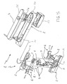
- the support structure 2 comprises a first and a second shell halves 14, 15 arranged to be coupled with each other to define a housing cavity for the transmission means 5 which is movable within this cavity.
- centring body 16 hooked to the shell halves 14 and 15 and the base element 20 are disposed at opposite sides of the sheet metal and actually clasp it.
- the driving element 3 or handle is arranged to be constrained to the support structure at an upper portion thereof so that it is movable in rotation around an axis 11.
- handle 3 in a rest condition, handle 3 will be disposed parallel to the base element 20, its extension axis being substantially vertical (arrangement shown in Fig. 1).
- a lock, of the cylinder type for example (not shown), contained in the housing seat 24 will enable the handle to be blocked to a vertical position allowing the cabinet to be locked or not.
- the driving handle 3 may consist of different components and also be provided with a closing lid 26 slidable along its extension axis on the main body of the handle to conceal/show access to the lock.
- the closing lid 26 is movable between a condition in which it prevents insertion of the key in a lock present in the handle and a position in which on the contrary insertion and unlocking of the lock is allowed.
- a grip portion 26a of said lid projects from the handle at the lower part thereof and allows easy extraction of the whole driving element 3 to enable rotation of the handle itself and therefore opening of the cabinet.
- the driving element 3 when in operation, is movable between at least one first and one second operating conditions; in particular it is movable in rotation from the first to the second operating conditions around axis 11 which is substantially coincident with the rotation axis of the rotating body 6 with which it is rigidly in engagement for rotation through a tailpiece 25.
- the previously mentioned transmission means 5 is moved by handle 3 and transmits motion to the locking means 4.
- This transmission means 5 comprises the hollow rotating body 6 driven in rotation by the tailpiece 25; body 6 in turn transmits motion to a transmission structure 7 interposed between the rotating body itself and the locking means 4 so as to enable displacement of the locking means 4, following movement of the rotating body 6, at least between a locked condition and an unlocked condition, as better specified in the following.
- the transmission structure 7 is of a deformable nature and its geometry varies when the locking means 4 moves from the locked condition to the unlocked condition.
- the transmission structure has its median axis bent on the rotating body 6 in the unlocked condition of the locking means 4, whereas its median axis is straight and in the extension of the axis of a slidable arm 8 in the locked condition of the locking means (Fig. 1).
- the same consists of a predetermined number of articulated elements 10 hinged on each other.
- first one of these elements is hinged on an appropriate expansion of the rotating body 6, whereas the last articulated element is hinged on the locking means 4.
- any number of articulated elements may be provided depending on the construction requirements and the strokes of the locking means.
- the support structure 2 is provided with appropriate shaped seats 12, 13 set to receive and guide the rotating body 6 and transmission structure 7 respectively, during movement.
- the shaped seats 12, 13 are defined on at least one and preferably both of the shell halves 14, 15.
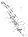
- the locking means 4 (see Fig. 4 for example) is made up of at least one slidable arm 8 having a first end 8a associated with the transmission structure 7 and a second end 8b in engagement with a bar 9 at a first end 9a thereof.
- Bar 9 may have any length depending on the operating requirements (bars of different sizes and shapes are shown in Fig. 4) and, at the other end 9b thereof, said bars are arranged in such a manner as to enable hooking to the closing bolts of a panel, door or the like.
- the preferred, although not exclusive, embodiment involves the presence of two transmission structures 7 in engagement with the rotating body 6 at opposite positions of the latter.
- Rotation of body 6 causes the transmission structure 7 to be pulled along with it deforming it from the straight condition shown in Fig. 1 to a condition of partial winding on the rotating body.
- This movement of the transmission structure 7 in turn involves a translation of the slidable arms along their axes, said arms in turn carrying bars 9 along with them in their movement.
- a rotation from the first (vertical) condition to the second (horizontal) operating condition of the driving element or handle involves a displacement from the locked condition to the unlocked condition of the locking means 4 and therefore enables opening of the cabinet door.
- the shaped seats 12 and 13 present on one of the shell halves 14, 15 guide both the rotating body and transmission structure 7 in their movement (the former in rotation and the latter on moving from the straight condition to the condition wound by the rotating body), and also guide the slidable arm 8 in a vertical translational movement.
- the invention achieves important advantages.
- the transmission structure enables concentration of stresses within the structure itself to be avoided as much as possible, thereby reducing accidental breaking of the device and increasing the operating life of same.
Landscapes
- Engineering & Computer Science (AREA)
- Mechanical Engineering (AREA)
- Lock And Its Accessories (AREA)
- Casings For Electric Apparatus (AREA)
Claims (10)
- Verriegelungsvorrichtung, umfassend:dadurch gekennzeichnet, dasseinen Tragaufbau (2);ein dem Tragaufbau (2) zugeordnetes und zwischen mindestens einer ersten und zweiten Arbeitsstellung verstellbares Betätigungsteil (3);Verriegelungsmittel (4), die bereitgestellt sind, zwischen einer Verriegelungsstellung und einer Entriegelungsstellung bewegt zu werden;Übertragungsmittel (5), die vom Betätigungsteil (3) verstellt werden und bereitgestellt sind, die Bewegung den Verriegelungsmitteln (4) zu übertragen, wobei eine Verstellung des Betätigungsteils von der ersten in die zweite Arbeitsstellung die Verstellung der Verriegelungsmittel (4) von der Verriegelungsstellung in die Entriegelungsstellung betragen, wobei die Bewegungsübertragungsmittel (5) einen Drehkörper (6), der in der Bewegung durch das Betätigungsteil (3) gesteuert wird, und eine Übertragungsstruktur (7) umfassen, die zwischen dem Drehkörper (6) und den Verriegelungsmitteln (4) zwischengeschalten ist, um zufolge der Bewegung des Drehkörpers (6) die Verstellung der Verriegelungsmittel (4) zwischen mindestens der Verriegelungsstellung und der Entriegelungsstellung zu erlauben,
die Übertragungsstruktur (7) eine verformbare Struktur ist, deren Geometrie von der Verriegelungsstellung in die Entriegelungsstellung der Verriegelungsmittel (4) geändert wird, wobei die Übertragungsstruktur (7) bevorzugter Weise eine im wesentlichen geradlinige Mittelachse in Fortsetzung der Achse des Schiebearmes (8) in Verriegelungsstellung der Verriegelungsmittel und eine Mittelachse aufweist, die um den Drehkörper (6) in Entriegelungsstellung der Verriegelungsmittel (4) herum gekrümmt ist. - Verriegelungsvorrichtung nach Anspruch 1, dadurch gekennzeichnet, dass die Verriegelungsmittel (4) umfassen:mindestens einen Schiebearm (8), der ein erstes, der Übertragungsstruktur (7) zugeordnetes Ende (8a); undeine Stange (9) aufweist, die an einem Ende (9a) am Schiebearm (8) angreift und dazu bereitgestellt ist, am anderen Ende (9b) am Riegel zum Schließen einer Tür, eines Flügels oder ähnlichen eingehakt zu werden.
- Verriegelungsvorrichtung nach einem beliebigen der vorstehenden Ansprüche, dadurch gekennzeichnet, dass die Übertragungsstruktur (7) zwischengeschaltet ist und vom Drehkörper (6) und von den Verriegelungsmitteln (4) trennbar und fähig ist, eine im wesentlichen drehende Bewegung des Drehkörpers (6) in eine im wesentlichen Translationsbewegung der Verriegelungsmittel (4) umzuwandeln, wobei die Übertragungsstruktur (7) bevorzugter Weise in der Lage ist, Schubwirkungen den Verriegelungsmitteln (4) während ihrer Verstellung in Richtung der Verriegelungsstellung und Zugwirkungen den Verriegelungsmitteln (4) während deren Verstellung in die Entriegelungsstellung zu übertagen.
- Verriegelungsvorrichtung nach einem beliebigen der vorstehenden Ansprüche, dadurch gekennzeichnet, dass die Übertragungsstruktur (7) eine vorgegebene Anzahl von gelenkigen Teilen (10) umfasst, die miteinander angelenkt sind, wobei ein erstes gelenkiges Teil am Drehkörper (6) angelenkt ist, während ein letztes gelenkiges Teil an den Verriegelungsmitteln (4) angelenkt ist.
- Verriegelungsvorrichtung nach einem beliebigen der vorstehenden Ansprüche, dadurch gekennzeichnet, dass das Betätigungsteil (3) von der ersten in die zweite Arbeitsstellung um eine Achse (11) drehbeweglich ist, die im wesentlichen mit der Drehachse des Drehkörpers (6) zusammenfällt.
- Verriegelungsvorrichtung nach einem beliebigen der vorstehenden Ansprüche, dadurch gekennzeichnet, dass der Tragaufbau (2) zweckmäßig geformte Aufnahmen (12, 13) aufweist, die bereitgestellt sind, während der Verstellung jeweils den Drehkörper (6) und die Übertragungsstruktur (7) aufzunehmen und zu führen.
- Verriegelungsvorrichtung nach einem beliebigen der vorstehenden Ansprüche, dadurch gekennzeichnet, dass sie zwei Übertragungsstrukturen (7) umfasst, die am Drehkörper (6) im Bereich von gegenüberliegenden Stellungen dieses letzteren angreifen.
- Verriegelungsvorrichtung nach einem beliebigen der vorstehenden Ansprüche, dadurch gekennzeichnet, dass der Tragaufbau (2) eine erste und eine zweite Halbschale (14, 15) umfasst, die bereitgestellt sind, eine Ausnehmung zur Aufnahme der Verriegelungsmittel (5) festzulegen, wobei die geformten Aufnahmen (12, 13) auf mindestens einer der Halbschalen (14, 15) festgelegt sind.
- Verriegelungsvorrichtung nach dem vorstehenden Anspruch, dadurch gekennzeichnet, dass der Tragaufbau (2) einen Zentrierkörper (16) umfasst, der mit zweckmäßigen Schultern (17) versehen ist, die geeignet sind, mit einer ersten, im wesentlichen gegenprofilierten Bohrung (18) eines Bleches (19) gekoppelt zu werden, wobei bevorzugter Weise der Zentrierkörper (16) getrennt und mit einer der Halbschalen (14, 15) und mit einem Basisteil (20) koppelbar ist, wobei der Zentrierkörper (16) und das Basisteil (20) in Zusammenbaustellung auf gegenüber dem Blech (19) abgewandten Seiten liegt.
- Mit Flügeln aus Metallblech versehener Schrank, umfassend eine Verriegelungsvorrichtung gemäß einem oder mehreren der vorstehenden Ansprüche.
Priority Applications (3)
| Application Number | Priority Date | Filing Date | Title |
|---|---|---|---|
| EP02425015A EP1329574B1 (de) | 2002-01-18 | 2002-01-18 | Verriegelungsvorrichtung |
| AT02425015T ATE302314T1 (de) | 2002-01-18 | 2002-01-18 | Verriegelungsvorrichtung |
| DE60205574T DE60205574T2 (de) | 2002-01-18 | 2002-01-18 | Verriegelungsvorrichtung |
Applications Claiming Priority (1)
| Application Number | Priority Date | Filing Date | Title |
|---|---|---|---|
| EP02425015A EP1329574B1 (de) | 2002-01-18 | 2002-01-18 | Verriegelungsvorrichtung |
Publications (2)
| Publication Number | Publication Date |
|---|---|
| EP1329574A1 EP1329574A1 (de) | 2003-07-23 |
| EP1329574B1 true EP1329574B1 (de) | 2005-08-17 |
Family
ID=8185829
Family Applications (1)
| Application Number | Title | Priority Date | Filing Date |
|---|---|---|---|
| EP02425015A Expired - Lifetime EP1329574B1 (de) | 2002-01-18 | 2002-01-18 | Verriegelungsvorrichtung |
Country Status (3)
| Country | Link |
|---|---|
| EP (1) | EP1329574B1 (de) |
| AT (1) | ATE302314T1 (de) |
| DE (1) | DE60205574T2 (de) |
Families Citing this family (2)
| Publication number | Priority date | Publication date | Assignee | Title |
|---|---|---|---|---|
| AU2009200703B2 (en) * | 2008-02-22 | 2014-06-19 | B&R Enclosures Pty Ltd | Reversible locking device (b) for a switching cabinet |
| DE102021124672A1 (de) | 2021-09-23 | 2023-03-23 | Emka Beschlagteile Gmbh & Co. Kg. | Verschluss |
Family Cites Families (4)
| Publication number | Priority date | Publication date | Assignee | Title |
|---|---|---|---|---|
| DE3676823D1 (de) * | 1986-09-25 | 1991-02-14 | Dieter Ramsauer | Stangenverschluss fuer blechschranktueren. |
| ES2139896T3 (es) * | 1994-04-20 | 2000-02-16 | Emka Beschlagteile | Sistema de cierre para cerradura interior variable. |
| DE29711737U1 (de) * | 1997-07-04 | 1998-10-29 | Ramsauer, Dieter, 42555 Velbert | Durch Vorhängeschloß sichtbare Schwenkhebelbetätigung für den Verschluß von Schaltschranktüren o.dgl. |
| DE20009771U1 (de) * | 2000-06-02 | 2000-09-07 | Emka Beschlagteile Gmbh & Co. Kg, 42551 Velbert | Stangenschloß für ein Verschlußsystem |
-
2002
- 2002-01-18 DE DE60205574T patent/DE60205574T2/de not_active Expired - Fee Related
- 2002-01-18 AT AT02425015T patent/ATE302314T1/de not_active IP Right Cessation
- 2002-01-18 EP EP02425015A patent/EP1329574B1/de not_active Expired - Lifetime
Also Published As
| Publication number | Publication date |
|---|---|
| EP1329574A1 (de) | 2003-07-23 |
| DE60205574D1 (de) | 2005-09-22 |
| ATE302314T1 (de) | 2005-09-15 |
| DE60205574T2 (de) | 2006-05-24 |
Similar Documents
| Publication | Publication Date | Title |
|---|---|---|
| US9790716B2 (en) | Opposed hook sliding door lock | |
| US8011702B2 (en) | Outer operational device for panic exit door lock | |
| US4368905A (en) | Exit door locking mechanism having multiple bolts | |
| KR0185243B1 (ko) | 창 또는 문의 슬리브 기어장치 | |
| DE112009000529T5 (de) | Schloss mit drehbarer Sperrklinke | |
| US20100031857A1 (en) | Sequential safe door opening | |
| EP3219886B1 (de) | Anti-panikdruckstange mit antriebseinrichtung | |
| AU2025202266A1 (en) | A lock assembly | |
| EP1329574A1 (de) | Verriegelungsvorrichtung | |
| US12084893B2 (en) | Gate latch | |
| EP0742332A1 (de) | Treibstangenverschlussbefestigungsanordnung | |
| EP1333140B1 (de) | Verriegelungsvorrichtung und Montageverfahren dazu | |
| US11060330B2 (en) | Tether lock | |
| KR200283418Y1 (ko) | 강화유리출입문 개폐장치 | |
| JP2004052218A (ja) | 開口部装置 | |
| EP1806706B1 (de) | Diebstahlgeschützter behälter für vergnügen und spiel von glücksspielautomaten | |
| KR0131915Y1 (ko) | 그레이팅 덮개용 잠금장치 | |
| US4718704A (en) | Latch assembly for a door or window | |
| JP3806895B2 (ja) | 開き窓の錠装置 | |
| EP1770232B1 (de) | Steuerungssystem für Paniktüren | |
| KR102574820B1 (ko) | 제어함용 다중도어 잠금장치 | |
| JP2818460B2 (ja) | 引き戸用電気錠 | |
| JP2001146865A (ja) | 扉 錠 | |
| JP4508758B2 (ja) | ボタン錠 | |
| JPH0323497Y2 (de) |
Legal Events
| Date | Code | Title | Description |
|---|---|---|---|
| PUAI | Public reference made under article 153(3) epc to a published international application that has entered the european phase |
Free format text: ORIGINAL CODE: 0009012 |
|
| AK | Designated contracting states |
Designated state(s): AT BE CH CY DE DK ES FI FR GB GR IE IT LI LU MC NL PT SE TR |
|
| AX | Request for extension of the european patent |
Extension state: AL LT LV MK RO SI |
|
| 17P | Request for examination filed |
Effective date: 20040116 |
|
| AKX | Designation fees paid |
Designated state(s): AT BE CH CY DE DK ES FI FR GB GR IE IT LI LU MC NL PT SE TR |
|
| 17Q | First examination report despatched |
Effective date: 20040705 |
|
| RAP1 | Party data changed (applicant data changed or rights of an application transferred) |
Owner name: GIUSSANI TECHNIQUES S.P.A. |
|
| GRAP | Despatch of communication of intention to grant a patent |
Free format text: ORIGINAL CODE: EPIDOSNIGR1 |
|
| GRAS | Grant fee paid |
Free format text: ORIGINAL CODE: EPIDOSNIGR3 |
|
| GRAA | (expected) grant |
Free format text: ORIGINAL CODE: 0009210 |
|
| RAP1 | Party data changed (applicant data changed or rights of an application transferred) |
Owner name: GIUSSANI TECHNIQUES S.P.A. |
|
| AK | Designated contracting states |
Kind code of ref document: B1 Designated state(s): AT BE CH CY DE DK ES FI FR GB GR IE IT LI LU MC NL PT SE TR |
|
| PG25 | Lapsed in a contracting state [announced via postgrant information from national office to epo] |
Ref country code: NL Free format text: LAPSE BECAUSE OF FAILURE TO SUBMIT A TRANSLATION OF THE DESCRIPTION OR TO PAY THE FEE WITHIN THE PRESCRIBED TIME-LIMIT Effective date: 20050817 Ref country code: BE Free format text: LAPSE BECAUSE OF FAILURE TO SUBMIT A TRANSLATION OF THE DESCRIPTION OR TO PAY THE FEE WITHIN THE PRESCRIBED TIME-LIMIT Effective date: 20050817 Ref country code: AT Free format text: LAPSE BECAUSE OF FAILURE TO SUBMIT A TRANSLATION OF THE DESCRIPTION OR TO PAY THE FEE WITHIN THE PRESCRIBED TIME-LIMIT Effective date: 20050817 Ref country code: TR Free format text: LAPSE BECAUSE OF FAILURE TO SUBMIT A TRANSLATION OF THE DESCRIPTION OR TO PAY THE FEE WITHIN THE PRESCRIBED TIME-LIMIT Effective date: 20050817 Ref country code: FI Free format text: LAPSE BECAUSE OF FAILURE TO SUBMIT A TRANSLATION OF THE DESCRIPTION OR TO PAY THE FEE WITHIN THE PRESCRIBED TIME-LIMIT Effective date: 20050817 |
|
| REG | Reference to a national code |
Ref country code: GB Ref legal event code: FG4D |
|
| REG | Reference to a national code |
Ref country code: CH Ref legal event code: EP |
|
| REG | Reference to a national code |
Ref country code: IE Ref legal event code: FG4D |
|
| REF | Corresponds to: |
Ref document number: 60205574 Country of ref document: DE Date of ref document: 20050922 Kind code of ref document: P |
|
| REG | Reference to a national code |
Ref country code: CH Ref legal event code: NV Representative=s name: ISLER & PEDRAZZINI AG |
|
| PG25 | Lapsed in a contracting state [announced via postgrant information from national office to epo] |
Ref country code: GR Free format text: LAPSE BECAUSE OF FAILURE TO SUBMIT A TRANSLATION OF THE DESCRIPTION OR TO PAY THE FEE WITHIN THE PRESCRIBED TIME-LIMIT Effective date: 20051117 Ref country code: DK Free format text: LAPSE BECAUSE OF FAILURE TO SUBMIT A TRANSLATION OF THE DESCRIPTION OR TO PAY THE FEE WITHIN THE PRESCRIBED TIME-LIMIT Effective date: 20051117 Ref country code: SE Free format text: LAPSE BECAUSE OF FAILURE TO SUBMIT A TRANSLATION OF THE DESCRIPTION OR TO PAY THE FEE WITHIN THE PRESCRIBED TIME-LIMIT Effective date: 20051117 |
|
| PG25 | Lapsed in a contracting state [announced via postgrant information from national office to epo] |
Ref country code: ES Free format text: LAPSE BECAUSE OF FAILURE TO SUBMIT A TRANSLATION OF THE DESCRIPTION OR TO PAY THE FEE WITHIN THE PRESCRIBED TIME-LIMIT Effective date: 20051128 |
|
| PG25 | Lapsed in a contracting state [announced via postgrant information from national office to epo] |
Ref country code: PT Free format text: LAPSE BECAUSE OF FAILURE TO SUBMIT A TRANSLATION OF THE DESCRIPTION OR TO PAY THE FEE WITHIN THE PRESCRIBED TIME-LIMIT Effective date: 20060117 |
|
| PG25 | Lapsed in a contracting state [announced via postgrant information from national office to epo] |
Ref country code: IE Free format text: LAPSE BECAUSE OF NON-PAYMENT OF DUE FEES Effective date: 20060118 |
|
| PG25 | Lapsed in a contracting state [announced via postgrant information from national office to epo] |
Ref country code: MC Free format text: LAPSE BECAUSE OF NON-PAYMENT OF DUE FEES Effective date: 20060131 Ref country code: LU Free format text: LAPSE BECAUSE OF NON-PAYMENT OF DUE FEES Effective date: 20060131 |
|
| NLV1 | Nl: lapsed or annulled due to failure to fulfill the requirements of art. 29p and 29m of the patents act | ||
| ET | Fr: translation filed | ||
| PLBE | No opposition filed within time limit |
Free format text: ORIGINAL CODE: 0009261 |
|
| STAA | Information on the status of an ep patent application or granted ep patent |
Free format text: STATUS: NO OPPOSITION FILED WITHIN TIME LIMIT |
|
| 26N | No opposition filed |
Effective date: 20060518 |
|
| REG | Reference to a national code |
Ref country code: IE Ref legal event code: MM4A |
|
| PGFP | Annual fee paid to national office [announced via postgrant information from national office to epo] |
Ref country code: DE Payment date: 20070111 Year of fee payment: 6 |
|
| PGFP | Annual fee paid to national office [announced via postgrant information from national office to epo] |
Ref country code: CH Payment date: 20070115 Year of fee payment: 6 |
|
| PGFP | Annual fee paid to national office [announced via postgrant information from national office to epo] |
Ref country code: GB Payment date: 20070117 Year of fee payment: 6 |
|
| REG | Reference to a national code |
Ref country code: CH Ref legal event code: PCAR Free format text: ISLER & PEDRAZZINI AG;POSTFACH 1772;8027 ZUERICH (CH) |
|
| PGFP | Annual fee paid to national office [announced via postgrant information from national office to epo] |
Ref country code: IT Payment date: 20070515 Year of fee payment: 6 |
|
| PGFP | Annual fee paid to national office [announced via postgrant information from national office to epo] |
Ref country code: FR Payment date: 20070109 Year of fee payment: 6 |
|
| REG | Reference to a national code |
Ref country code: CH Ref legal event code: PL |
|
| GBPC | Gb: european patent ceased through non-payment of renewal fee |
Effective date: 20080118 |
|
| PG25 | Lapsed in a contracting state [announced via postgrant information from national office to epo] |
Ref country code: LI Free format text: LAPSE BECAUSE OF NON-PAYMENT OF DUE FEES Effective date: 20080131 Ref country code: DE Free format text: LAPSE BECAUSE OF NON-PAYMENT OF DUE FEES Effective date: 20080801 Ref country code: CH Free format text: LAPSE BECAUSE OF NON-PAYMENT OF DUE FEES Effective date: 20080131 |
|
| PG25 | Lapsed in a contracting state [announced via postgrant information from national office to epo] |
Ref country code: CY Free format text: LAPSE BECAUSE OF FAILURE TO SUBMIT A TRANSLATION OF THE DESCRIPTION OR TO PAY THE FEE WITHIN THE PRESCRIBED TIME-LIMIT Effective date: 20050817 |
|
| REG | Reference to a national code |
Ref country code: FR Ref legal event code: ST Effective date: 20081029 |
|
| PG25 | Lapsed in a contracting state [announced via postgrant information from national office to epo] |
Ref country code: GB Free format text: LAPSE BECAUSE OF NON-PAYMENT OF DUE FEES Effective date: 20080118 |
|
| PG25 | Lapsed in a contracting state [announced via postgrant information from national office to epo] |
Ref country code: FR Free format text: LAPSE BECAUSE OF NON-PAYMENT OF DUE FEES Effective date: 20080131 |
|
| PG25 | Lapsed in a contracting state [announced via postgrant information from national office to epo] |
Ref country code: IT Free format text: LAPSE BECAUSE OF NON-PAYMENT OF DUE FEES Effective date: 20080118 |