EP1329587A2 - Appareil pour maintenir deux colonnes de tubulaires - Google Patents
Appareil pour maintenir deux colonnes de tubulaires Download PDFInfo
- Publication number
- EP1329587A2 EP1329587A2 EP02102890A EP02102890A EP1329587A2 EP 1329587 A2 EP1329587 A2 EP 1329587A2 EP 02102890 A EP02102890 A EP 02102890A EP 02102890 A EP02102890 A EP 02102890A EP 1329587 A2 EP1329587 A2 EP 1329587A2
- Authority
- EP
- European Patent Office
- Prior art keywords
- tubulars
- string
- converting member
- body parts
- retaining
- Prior art date
- Legal status (The legal status is an assumption and is not a legal conclusion. Google has not performed a legal analysis and makes no representation as to the accuracy of the status listed.)
- Granted
Links
Images



Classifications
-
- E—FIXED CONSTRUCTIONS
- E21—EARTH OR ROCK DRILLING; MINING
- E21B—EARTH OR ROCK DRILLING; OBTAINING OIL, GAS, WATER, SOLUBLE OR MELTABLE MATERIALS OR A SLURRY OF MINERALS FROM WELLS
- E21B33/00—Sealing or packing boreholes or wells
- E21B33/02—Surface sealing or packing
- E21B33/03—Well heads; Setting-up thereof
- E21B33/04—Casing heads; Suspending casings or tubings in well heads
- E21B33/047—Casing heads; Suspending casings or tubings in well heads for plural tubing strings
-
- E—FIXED CONSTRUCTIONS
- E21—EARTH OR ROCK DRILLING; MINING
- E21B—EARTH OR ROCK DRILLING; OBTAINING OIL, GAS, WATER, SOLUBLE OR MELTABLE MATERIALS OR A SLURRY OF MINERALS FROM WELLS
- E21B19/00—Handling rods, casings, tubes or the like outside the borehole, e.g. in the derrick; Apparatus for feeding the rods or cables
- E21B19/02—Rod or cable suspensions
- E21B19/06—Elevators, i.e. rod- or tube-gripping devices
-
- E—FIXED CONSTRUCTIONS
- E21—EARTH OR ROCK DRILLING; MINING
- E21B—EARTH OR ROCK DRILLING; OBTAINING OIL, GAS, WATER, SOLUBLE OR MELTABLE MATERIALS OR A SLURRY OF MINERALS FROM WELLS
- E21B19/00—Handling rods, casings, tubes or the like outside the borehole, e.g. in the derrick; Apparatus for feeding the rods or cables
- E21B19/02—Rod or cable suspensions
- E21B19/06—Elevators, i.e. rod- or tube-gripping devices
- E21B19/07—Slip-type elevators
-
- E—FIXED CONSTRUCTIONS
- E21—EARTH OR ROCK DRILLING; MINING
- E21B—EARTH OR ROCK DRILLING; OBTAINING OIL, GAS, WATER, SOLUBLE OR MELTABLE MATERIALS OR A SLURRY OF MINERALS FROM WELLS
- E21B19/00—Handling rods, casings, tubes or the like outside the borehole, e.g. in the derrick; Apparatus for feeding the rods or cables
- E21B19/10—Slips; Spiders ; Catching devices
-
- E—FIXED CONSTRUCTIONS
- E21—EARTH OR ROCK DRILLING; MINING
- E21B—EARTH OR ROCK DRILLING; OBTAINING OIL, GAS, WATER, SOLUBLE OR MELTABLE MATERIALS OR A SLURRY OF MINERALS FROM WELLS
- E21B33/00—Sealing or packing boreholes or wells
- E21B33/02—Surface sealing or packing
- E21B33/03—Well heads; Setting-up thereof
- E21B33/04—Casing heads; Suspending casings or tubings in well heads
- E21B33/0407—Casing heads; Suspending casings or tubings in well heads with a suspended electrical cable
Definitions
- the invention relates to an apparatus for retaining two strings of tubulars, and is particularly but not exclusively for use as a spider in the platform of an oil rig and also for use in an elevator of an oil rig.
- the invention also relates to a device for retaining a string of tubulars, the device comprising at least one body part having a curved tapered surface upon which inserts are located for engagement with the string of tubulars.
- a retaining device is used in a platform of the rig, know as a spider, and a corresponding retaining device in an elevator of the rig.
- the string of tubulars is initially retained from falling down the well by the spider. Additional stands of tubulars are moved from a rack to a position above the spider. The stand of tubulars is connected to the string.
- the device in the elevator is placed around the top of the lengthened string of tubulars.
- the spider is then released from engagement with the string, and the device in the elevator now takes the full weight of the lengthened string of tubulars.
- the elevator moves downwardly towards the spider, lowering the lengthened string of tubulars.
- the spider engages the lengthened string of tubulars and the elevator is subsequently released from engagement therewith. This process is reversed for pulling a string of tubulars out of a well.
- a device comprising at least one body part (203) having a curved tapered surface (202) upon which inserts are located for engagement with said string of tubulars characterised in that said curved tapered surface comprises a recess for the passage of cables.
- FIG. 1 there is shown a prior art device for retaining a single string of tubulars.
- the device comprises two body parts 1 and 2.
- the body parts 1 and 2 are generally triangular in shape and are hinged in relation to one another by means of inter engaging rows of eyelets 3 and 4 and a hinge pin 5 at one corner thereof.
- Each row of eyelets 3 and 4 is integral with the respective body part 1 and 2.
- the body parts 1 and 2 also have inter engaging rows of eyelets 6 and 7 on the opposite corners thereof.
- the body parts 1 and 2 may be locked together by use of a locking pin 8 insertable through the rows of eyelets 6 and 7.
- the body parts 1 and 2 are provided with semicircular tapered surfaces 9 and 10 which taper downwardly from a first diameter 11 to a second small diameter 12.
- corresponding tapered inserts are provided in the tapered surface for gripping the tubular which runs therethrough. The weight of the tubular string will be transferred from the tapered inserts to the tapered surfaces 9 and 10.
- Body part 1 also comprises an opening 14 which runs from the top to the bottom of the body part 1 and lies parallel to the tapered surface 9.
- the opening 14 is provided for receiving an actuating piston and cylinder (not shown) which, in use, moves the tapered inserts along the tapered surfaces 9 and 10 for engaging or disengaging the inserts with a tubular.
- the actuating piston and cylinder may be hydraulic or pneumatic.
- two such devices are used.
- One device is mounted in an elevator and the other is mounted in the floor of an oil rig.
- a string of tubulars, such as casing is first retained in the device mounted in the floor of the oil rig.
- a section of casing may then be added or taken away from the string of casing thereabove. This may be achieved by using tubular handling equipment to move the section of casing to a position above the string of casing, and a tong to facilitate connection or disconnection of the section of casing to or from the string of casing.
- the device mounted in the elevator may now be used to retain the section of casing extending above the device in the floor of the oil rig.
- the device in the floor of the oil rig may now be disengaged from the string of tubulars.
- the elevator is then operated to lower or raise the entire string of casing.
- the device in the rig floor is then used to retain the string of casing once again.
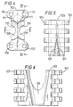
- FIG. 1 there is shown an apparatus for retaining two strings of tubulars, the apparatus being in accordance with the invention.
- the apparatus is generally identified by the reference number 100.
- the apparatus 100 comprises body part 101 which is generally similar to body part 1 of Figure 1, body part 102 which is a mirror image of the body part 1 of Figure 1 and a converting member 103.
- the converting member 103 is generally rectangular in shape with rows of eyelets 104, 105,106,107 at each corner thereof.
- the converting member is provided with two semicircular tapered surfaces 108,109 which taper downwardly from a first diameter 100 to a smaller diameter 111.
- the semicircular tapered surfaces 108,109 oppose each other and merge as the diameter increases from the small diameter to the front diameter as shown in Figure 6.
- corresponding tapered inserts are provided on the tapered surface 108,109 for gripping a tubular.
- the converting member 103 is arranged between the body parts 101 and 102 and are hinged thereto.
- a row of eyelets 112 is integral with one comer of the body part 101 and inter engages with the row of eyelets 104 of the converting member 103 and a hinge pin 113 is located therethrough.
- a row of eyelets 114 is integral with a first corner of the body part 102 and inter engages with the row of eyelets 105 of the converting member 103 and a hinge pin 115 is located therethough.
- a row of eyelets 116 is integral with an opposing comer of body part 101 and inter engages with a row of eyelets 106 of the converting member 103 and a locking pin 117 may be inserted therethrough to lock the body part 101 to the converting member 103.
- a row of eyelets 118 is integral with an opposing corner of body part 102 and inter engages with the row of eyelets 107 of the converting member 103 and a locking pin 119 may be inserted therethrough to lock the body part 102 to the converting member 103.
- Each of the body parts 101 and 102 is provided with corresponding tapered surfaces 120 and 121 and with openings 122 and 123 for receiving actuating pistons and cylinders as described with reference to the device of Figure 1.
- two such apparatuses are used, one as a spider in the platform of an oil rig and the other in the elevator of the oil rig.
- the method of operation is much the same as that described with reference to the device of Figure 1, except that two actuating pistons and cylinders are used to move the tapered inserts along the tapered surfaces 108, 109, 120 and 121 for engaging or disengaging the inserts with a tubular.
- FIG. 7 there is shown a device, generally identified by reference numeral 200.
- the device 200 is generally similar to the device shown in Figure 1 with the additional feature of a recess 201 in the tapered surface 202 of the body part 203.
- the recess 201 in sized to accommodate a loom of cables running substantially parallel to the strings of tubulars. This enables the cable strings to pass through the device for retaining a string of tubulars, for example, through a spider.
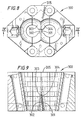
- FIGS 8 and 9 shows an apparatus generally identified by reference numeral 300.
- the device 200 is generally similar to the apparatus 100 of Figure 2 with the additional feature of a recess 301 and 302 in each of the tapered surfaces 303 and 304 of the converting member 305.
- the recesses 301 and 302 are sized to accommodate a loom of cables running substantially parallel to the two strings of tubulars. This enables the cable strings to pass through the device for retaining a string of tubulars, for example, through a spider.
- apparatuses could be used for coiled tubing, as well as tool strings, strings of drill pipe, casing and liners.
Landscapes
- Engineering & Computer Science (AREA)
- Geology (AREA)
- Mining & Mineral Resources (AREA)
- Life Sciences & Earth Sciences (AREA)
- General Life Sciences & Earth Sciences (AREA)
- Fluid Mechanics (AREA)
- Environmental & Geological Engineering (AREA)
- Physics & Mathematics (AREA)
- Geochemistry & Mineralogy (AREA)
- Mechanical Engineering (AREA)
- Earth Drilling (AREA)
- Shaping Of Tube Ends By Bending Or Straightening (AREA)
- Lining Or Joining Of Plastics Or The Like (AREA)
- Supports For Plants (AREA)
- Blinds (AREA)
- Prostheses (AREA)
Applications Claiming Priority (3)
| Application Number | Priority Date | Filing Date | Title |
|---|---|---|---|
| DE19747468A DE19747468C1 (de) | 1997-10-28 | 1997-10-28 | Klemmvorrichtung zum Halten von Rohren |
| DE19747468 | 1997-10-28 | ||
| EP98951562A EP1027522B1 (fr) | 1997-10-28 | 1998-10-27 | Appareil pour maintenir deux colonnes de tubulaires |
Related Parent Applications (1)
| Application Number | Title | Priority Date | Filing Date |
|---|---|---|---|
| EP98951562A Division EP1027522B1 (fr) | 1997-10-28 | 1998-10-27 | Appareil pour maintenir deux colonnes de tubulaires |
Publications (3)
| Publication Number | Publication Date |
|---|---|
| EP1329587A2 true EP1329587A2 (fr) | 2003-07-23 |
| EP1329587A3 EP1329587A3 (fr) | 2004-01-14 |
| EP1329587B1 EP1329587B1 (fr) | 2004-09-08 |
Family
ID=7846802
Family Applications (2)
| Application Number | Title | Priority Date | Filing Date |
|---|---|---|---|
| EP02102890A Expired - Lifetime EP1329587B1 (fr) | 1997-10-28 | 1998-10-27 | Appareil pour maintenir deux colonnes de tubulaires |
| EP98951562A Expired - Lifetime EP1027522B1 (fr) | 1997-10-28 | 1998-10-27 | Appareil pour maintenir deux colonnes de tubulaires |
Family Applications After (1)
| Application Number | Title | Priority Date | Filing Date |
|---|---|---|---|
| EP98951562A Expired - Lifetime EP1027522B1 (fr) | 1997-10-28 | 1998-10-27 | Appareil pour maintenir deux colonnes de tubulaires |
Country Status (7)
| Country | Link |
|---|---|
| US (3) | US6422311B1 (fr) |
| EP (2) | EP1329587B1 (fr) |
| AU (1) | AU9752398A (fr) |
| CA (1) | CA2307630C (fr) |
| DE (3) | DE19747468C1 (fr) |
| NO (1) | NO319487B1 (fr) |
| WO (1) | WO1999022111A1 (fr) |
Families Citing this family (9)
| Publication number | Priority date | Publication date | Assignee | Title |
|---|---|---|---|---|
| US7249637B2 (en) | 1997-09-02 | 2007-07-31 | Weatherford/Lamb, Inc. | Method and device to clamp control lines to tubulars |
| DE19747468C1 (de) * | 1997-10-28 | 1999-04-01 | Weatherford Oil Tool | Klemmvorrichtung zum Halten von Rohren |
| US6987908B2 (en) * | 2001-08-24 | 2006-01-17 | T-Networks, Inc. | Grating dispersion compensator and method of manufacture |
| CA2539319C (fr) * | 2003-09-19 | 2010-05-25 | Weatherford/Lamb, Inc. | Fausse rotation automatique |
| US7717184B2 (en) * | 2004-01-15 | 2010-05-18 | Weatherford/Lamb, Inc. | Safety interlock for control lines |
| US20060065407A1 (en) * | 2004-09-30 | 2006-03-30 | Patterson Services, Inc. | Apparatus and method for handling umbilical or control lines for tubing of a well |
| CN101343985B (zh) * | 2008-08-27 | 2011-07-27 | 中国石油化工股份有限公司胜利油田分公司采油工艺研究院 | 横梁式卡管器 |
| CN112483020A (zh) * | 2020-12-16 | 2021-03-12 | 戴忠宁 | 一种新式采油井口载荷转换装置 |
| CN114320245B (zh) * | 2021-10-21 | 2025-12-23 | 山东交通学院 | 便携式套管安装机 |
Family Cites Families (98)
| Publication number | Priority date | Publication date | Assignee | Title |
|---|---|---|---|---|
| US1541669A (en) | 1924-11-10 | 1925-06-09 | Robert B Summers | Casing spider |
| US2048682A (en) * | 1934-07-16 | 1936-07-28 | John B Borgadt | Electric tube welding machine |
| US2063361A (en) | 1936-06-02 | 1936-12-08 | Lawrence F Baash | Slip |
| US2298507A (en) * | 1939-10-06 | 1942-10-13 | Arthur J Penick | Elevator |
| US2381929A (en) * | 1940-09-06 | 1945-08-14 | Schlumberger Marcel | Well conditioning apparatus |
| US2589159A (en) | 1948-02-19 | 1952-03-11 | Standard Oil Dev Co | Hold-down slip assembly |
| US2620420A (en) * | 1952-02-11 | 1952-12-02 | Utility Appliance Corp | Welding machine |
| US2904836A (en) * | 1956-04-05 | 1959-09-22 | Deluxe Coils Inc | Centrifugal casting apparatus particularly for plastic tubing |
| US2988145A (en) * | 1956-12-03 | 1961-06-13 | Baker Oil Tools Inc | Well bore drilling and cementing apparatus |
| US2934148A (en) * | 1957-04-12 | 1960-04-26 | Cameron Iron Works Inc | Multiple zone well completion |
| US2986364A (en) * | 1959-01-06 | 1961-05-30 | Walter H Vestal | Pump hose handling apparatus |
| US3330354A (en) * | 1959-01-19 | 1967-07-11 | Brown Oil Tools | Pipe hanger assemblies and methods of running and removing multiple strings in well bores |
| US3063509A (en) * | 1959-05-25 | 1962-11-13 | William C Guier | Apparatus for handling stands of pipe |
| US3068344A (en) * | 1960-07-06 | 1962-12-11 | Continental Can Co | Combination electrical and mechanical can separating means on continuous welding machines |
| US3171730A (en) * | 1960-09-19 | 1965-03-02 | Owens Illinois Glass Co | Method and apparatus for forming mouth portions of small glass bottles |
| US3099323A (en) * | 1961-08-02 | 1963-07-30 | Benjamin F Kelley | Transfer platform for drill pipe elevators |
| US3188708A (en) | 1962-03-12 | 1965-06-15 | Homer W O'haver | Slip assembly for parallel tubing strings |
| US3287776A (en) * | 1964-01-13 | 1966-11-29 | Cicero C Brown | Multiple string manual operated elevator |
| US3421130A (en) * | 1964-10-12 | 1969-01-07 | Westinghouse Electric Corp | Fuse and disconnect device for mounting inside a high voltage bushing |
| US3393549A (en) * | 1965-04-29 | 1968-07-23 | Walker Mfg Co | Tube machine |
| US3413046A (en) * | 1967-03-14 | 1968-11-26 | Int Research & Dev Co Ltd | Balancing support stand |
| DE1290148B (de) * | 1967-05-13 | 1969-03-06 | Bayer Ag | Verfahren zur Herstellung von 4, 4'-Dinitrodiphenylaether |
| US3618144A (en) * | 1969-03-06 | 1971-11-09 | North American Rockwell | Cushioning assembly |
| US3675278A (en) * | 1970-07-30 | 1972-07-11 | Thurman O Powell | Combination elevator and spider |
| US3740801A (en) * | 1971-08-23 | 1973-06-26 | Hydril Co | Retention of pressure line to well tubing |
| US3757387A (en) * | 1971-12-17 | 1973-09-11 | Continental Oil Co | Apparatus for securing small diameter conduit to a larger diameter tubing string or the like |
| US3748702A (en) | 1972-06-15 | 1973-07-31 | C Brown | Automated pipe handling apparatus |
| US3907338A (en) * | 1974-06-14 | 1975-09-23 | Zapata Pipeline Technology Inc | Clamp and press for joining dual pipes |
| SE400478B (sv) * | 1975-01-13 | 1978-04-03 | Svenska Flaektfabriken Ab | Anordning for avlegsnande respektive tomning eller inspektion av filter, serskilt slangfilter |
| US4035012A (en) * | 1975-12-31 | 1977-07-12 | Guier William C | Dual elevators |
| US4100780A (en) * | 1976-01-02 | 1978-07-18 | Frank Sassak | Program controlled tube bending machine and a binary feed mechanism for use therein |
| US4090565A (en) * | 1976-09-13 | 1978-05-23 | Gray Tool Company | Control line tubing hanger |
| US4084739A (en) * | 1977-02-28 | 1978-04-18 | Wisconsin Centrifugal, Inc. | Apparatus and method for aligning and welding tubular metal components together |
| US4126348A (en) * | 1977-05-05 | 1978-11-21 | Bj-Hughes, Inc. | Universal handling head for a pipe racker |
| US4417846A (en) * | 1977-12-09 | 1983-11-29 | Hydra-Rig, Inc. | Traveling block elevator latch assembly |
| CA1087162A (fr) | 1978-02-13 | 1980-10-07 | George I Boyadjieff | Coins de retenue |
| US4208158A (en) * | 1978-04-10 | 1980-06-17 | Franklin Enterprises, Inc. | Auxiliary offshore rig and methods for using same |
| US4209066A (en) * | 1978-11-17 | 1980-06-24 | Watson Barry R | Method and apparatus for running tubular goods into and out of a borehole |
| US4354706A (en) | 1980-06-02 | 1982-10-19 | Bilco Tools, Inc. | Dual string elevators |
| US4326745A (en) * | 1980-06-30 | 1982-04-27 | Guier And Affiliates, Inc. | Link control system for use with dual elevators |
| US4318499A (en) * | 1980-08-18 | 1982-03-09 | Hamilton Joel A | Retainer and propulsion apparatus carried in a self-contained handle for use with a removable cartridge |
| US4396216A (en) * | 1980-09-18 | 1983-08-02 | Hughes Tool Company | Link engaging pipe elevator |
| US4381584A (en) * | 1980-12-15 | 1983-05-03 | Bilco Tools, Inc. | Dual string spider |
| US4421447A (en) * | 1981-03-09 | 1983-12-20 | Zena Equipment, Inc. | Elevator transfer and support system |
| US4422504A (en) * | 1981-03-16 | 1983-12-27 | Moore Boyd B | Protective clamp assembly |
| US4523645A (en) * | 1981-05-26 | 1985-06-18 | Moore Boyd B | Method of and apparatus for moving reeled material into and retrieving it from the upper end of a well bore in the earth's surface |
| US4489016A (en) * | 1983-02-11 | 1984-12-18 | Capital Controls Company, Inc. | Apparatus for diffusing gases into liquids |
| US4608754A (en) * | 1983-03-16 | 1986-09-02 | Kloster Kenneth D | Power driven tube cutter |
| US4489794A (en) * | 1983-05-02 | 1984-12-25 | Varco International, Inc. | Link tilting mechanism for well rigs |
| US4543998A (en) * | 1983-11-17 | 1985-10-01 | Regal International, Inc. | Protector clamp for well control lines |
| US4709574A (en) * | 1984-03-02 | 1987-12-01 | Vulcan Tool Company | Machine for cold forming small tubular elements |
| US4600054A (en) * | 1984-03-30 | 1986-07-15 | Equipment Renewal Company | Tubing hanger assembly |
| US4643259A (en) * | 1984-10-04 | 1987-02-17 | Autobust, Inc. | Hydraulic drill string breakdown and bleed off unit |
| US4697830A (en) * | 1984-12-31 | 1987-10-06 | Petro-Tube, Inc. | Stabbing guide |
| US4632739A (en) * | 1985-07-19 | 1986-12-30 | Lavalley Industrial Plastics, Inc. | Electrolytic cell head with replaceable insert and method of protecting the same |
| US4603737A (en) * | 1985-08-29 | 1986-08-05 | Spikes Hugh D | Line protector |
| US4700692A (en) * | 1985-12-23 | 1987-10-20 | Baumgartner George C | Surgical implantation method and apparatus |
| US4715456A (en) | 1986-02-24 | 1987-12-29 | Bowen Tools, Inc. | Slips for well pipe |
| US4809735A (en) * | 1986-11-19 | 1989-03-07 | Perfection Corporation | Valve and tapping tee apparatus and method |
| US4843945A (en) * | 1987-03-09 | 1989-07-04 | National-Oilwell | Apparatus for making and breaking threaded well pipe connections |
| US4773827A (en) * | 1987-07-23 | 1988-09-27 | Hydro-Thermal Corporation | Liquid heating apparatus with temperature control system |
| US4800968A (en) * | 1987-09-22 | 1989-01-31 | Triten Corporation | Well apparatus with tubular elevator tilt and indexing apparatus and methods of their use |
| CA1302391C (fr) * | 1987-10-09 | 1992-06-02 | Keith M. Haney | Languettes pour tubage compact utilise avec machine de forage a entrainement de tete |
| FR2658972B1 (fr) * | 1990-02-23 | 1992-05-15 | Elf Aquitaine | Dispositif de rechauffage de la colonne de production d'un puits et procede de mise en place des enroulements de rechauffage. |
| US5042601A (en) * | 1990-07-23 | 1991-08-27 | Bilco Tools, Inc. | Triple tool with sliding spider bowl |
| US5083356A (en) | 1990-10-04 | 1992-01-28 | Exxon Production Research Company | Collar load support tubing running procedure |
| GB9207388D0 (en) * | 1992-04-03 | 1992-05-13 | Jordan Leslie E | Clamps for use with well tubulars |
| US5330000A (en) * | 1992-09-22 | 1994-07-19 | Halliburton Company | Squeeze packer latch |
| US5335756A (en) | 1992-12-22 | 1994-08-09 | Bilco Tools, Inc. | Slip-type gripping assembly |
| US5528830A (en) * | 1994-02-18 | 1996-06-25 | Hansen; Fredrick M. | Rotary cutting tool for tubing, conduit and the like |
| US6023027A (en) * | 1996-05-03 | 2000-02-08 | Neff; Scott E. | Cable guard having a hinge rod and for protecting cables extending along a tubing string |
| US5907768A (en) * | 1996-08-16 | 1999-05-25 | Kobe Steel Usa Inc. | Methods for fabricating microelectronic structures including semiconductor islands |
| US6056060A (en) * | 1996-08-23 | 2000-05-02 | Weatherford/Lamb, Inc. | Compensator system for wellbore tubulars |
| US6378399B1 (en) * | 1997-09-15 | 2002-04-30 | Daniel S. Bangert | Granular particle gripping surface |
| US5848647A (en) | 1996-11-13 | 1998-12-15 | Frank's Casing Crew & Rental Tools, Inc. | Pipe gripping apparatus |
| US5791410A (en) * | 1997-01-17 | 1998-08-11 | Frank's Casing Crew & Rental Tools, Inc. | Apparatus and method for improved tubular grip assurance |
| NO305668B1 (no) | 1997-08-27 | 1999-07-05 | Karluf Hagen | Apparat og fremgangsmÕte til montering av en sammenhengende ledning i et spor i en r°rstreng |
| GB9718543D0 (en) * | 1997-09-02 | 1997-11-05 | Weatherford Lamb | Method and apparatus for aligning tubulars |
| US7249637B2 (en) * | 1997-09-02 | 2007-07-31 | Weatherford/Lamb, Inc. | Method and device to clamp control lines to tubulars |
| US6742596B2 (en) * | 2001-05-17 | 2004-06-01 | Weatherford/Lamb, Inc. | Apparatus and methods for tubular makeup interlock |
| DE19747468C1 (de) * | 1997-10-28 | 1999-04-01 | Weatherford Oil Tool | Klemmvorrichtung zum Halten von Rohren |
| DE19814033B4 (de) | 1998-03-30 | 2006-01-05 | Tracto-Technik Paul Schmidt Spezialmaschinen | Bohrgestängeführung und Bohrgerät mit Bohrgestängeführung |
| US6089338A (en) | 1998-04-03 | 2000-07-18 | Frank's Casing Crew And Rental Tools, Inc. | Flush mounted self aligning spider |
| MXPA01003057A (es) * | 1998-09-25 | 2003-07-14 | Errol A Sonnier | Sistema, aparato y metodo para instalar lineas de control en un pozo. |
| US6192981B1 (en) * | 1999-06-07 | 2001-02-27 | True Turn Machine, Inc. | Coiled tubing hanger assembly |
| US6237684B1 (en) * | 1999-06-11 | 2001-05-29 | Frank's Casing Crewand Rental Tools, Inc. | Pipe string handling apparatus and method |
| CA2284428A1 (fr) | 1999-10-01 | 2001-04-01 | Universe Machine Corporation | Support de tige a coins ameliore |
| GB2355030A (en) | 1999-10-06 | 2001-04-11 | Weatherford Lamb | Bushing for a drilling rig |
| US6412554B1 (en) | 2000-03-14 | 2002-07-02 | Weatherford/Lamb, Inc. | Wellbore circulation system |
| US6651737B2 (en) * | 2001-01-24 | 2003-11-25 | Frank's Casing Crew And Rental Tools, Inc. | Collar load support system and method |
| US6640939B2 (en) * | 2001-10-09 | 2003-11-04 | David A. Buck | Snubbing unit with improved slip assembly |
| CN100356032C (zh) * | 2002-01-04 | 2007-12-19 | 瓦克I/P公司 | 具有承载环的管子夹持结构 |
| US6889772B2 (en) * | 2002-10-23 | 2005-05-10 | Frank's International, Inc. | Method and apparatus for installing control lines in a well |
| US7216716B2 (en) * | 2002-12-10 | 2007-05-15 | Frank's Casing Crew & Rental Tools, Inc | Control line manipulating arm and method of using same |
| US7222677B2 (en) * | 2002-12-10 | 2007-05-29 | Frank's Casing Crew & Rental Tools, Inc. | Control line guide and method of using same |
| US6920931B1 (en) * | 2002-12-10 | 2005-07-26 | Frank's Casing Crew And Rental Tools, Inc. | Control line guide |
| WO2004090279A1 (fr) * | 2003-04-04 | 2004-10-21 | Weatherford/Lamb, Inc. | Procede et appareil de manipulation de materiel tubulaire pour puits de forage |
| US7044216B2 (en) * | 2003-11-05 | 2006-05-16 | Grant Prideco, L.P. | Large diameter flush-joint pipe handling system |
-
1997
- 1997-10-28 DE DE19747468A patent/DE19747468C1/de not_active Expired - Fee Related
-
1998
- 1998-10-27 DE DE69826154T patent/DE69826154D1/de not_active Expired - Lifetime
- 1998-10-27 DE DE69815140T patent/DE69815140T2/de not_active Expired - Lifetime
- 1998-10-27 EP EP02102890A patent/EP1329587B1/fr not_active Expired - Lifetime
- 1998-10-27 WO PCT/GB1998/003198 patent/WO1999022111A1/fr not_active Ceased
- 1998-10-27 EP EP98951562A patent/EP1027522B1/fr not_active Expired - Lifetime
- 1998-10-27 CA CA002307630A patent/CA2307630C/fr not_active Expired - Fee Related
- 1998-10-27 US US09/530,197 patent/US6422311B1/en not_active Expired - Lifetime
- 1998-10-27 AU AU97523/98A patent/AU9752398A/en not_active Abandoned
-
2000
- 2000-03-01 NO NO20001032A patent/NO319487B1/no not_active IP Right Cessation
-
2002
- 2002-06-18 US US10/174,416 patent/US7124828B2/en not_active Expired - Fee Related
-
2006
- 2006-10-23 US US11/552,023 patent/US7673691B2/en not_active Expired - Fee Related
Also Published As
| Publication number | Publication date |
|---|---|
| DE69826154D1 (de) | 2004-10-14 |
| EP1027522A1 (fr) | 2000-08-16 |
| US7124828B2 (en) | 2006-10-24 |
| DE19747468C1 (de) | 1999-04-01 |
| US20070102162A1 (en) | 2007-05-10 |
| US20040040701A1 (en) | 2004-03-04 |
| US7673691B2 (en) | 2010-03-09 |
| EP1027522B1 (fr) | 2003-05-28 |
| NO319487B1 (no) | 2005-08-22 |
| US6422311B1 (en) | 2002-07-23 |
| NO20001032D0 (no) | 2000-03-01 |
| CA2307630C (fr) | 2006-12-12 |
| DE69815140D1 (de) | 2003-07-03 |
| WO1999022111A1 (fr) | 1999-05-06 |
| EP1329587B1 (fr) | 2004-09-08 |
| NO20001032L (no) | 2000-04-14 |
| EP1329587A3 (fr) | 2004-01-14 |
| DE69815140T2 (de) | 2004-02-26 |
| CA2307630A1 (fr) | 1999-05-06 |
| AU9752398A (en) | 1999-05-17 |
Similar Documents
| Publication | Publication Date | Title |
|---|---|---|
| US8381818B2 (en) | Apparatus for, and method of, landing items at a well location | |
| US7681631B2 (en) | Automatic false rotary | |
| US6920926B2 (en) | Top drive well casing system | |
| US6349764B1 (en) | Drilling rig, pipe and support apparatus | |
| EP1078146B1 (fr) | Appareil et procede permettant de faciliter la connexion d'un element tubulaire avec un train d'elements tubulaires | |
| US6644413B2 (en) | Method of landing items at a well location | |
| EP1329587B1 (fr) | Appareil pour maintenir deux colonnes de tubulaires | |
| US6378614B1 (en) | Method of landing items at a well location | |
| US7025147B2 (en) | Apparatus for, and method of, landing items at a well location | |
| US6364012B1 (en) | Drill pipe handling apparatus | |
| US20120085550A1 (en) | Method and apparatus for stabbing tubular goods | |
| EP1295006B1 (fr) | Dispositif pour manutention de tuyaux et technique de descente de pieces dans un puits |
Legal Events
| Date | Code | Title | Description |
|---|---|---|---|
| PUAI | Public reference made under article 153(3) epc to a published international application that has entered the european phase |
Free format text: ORIGINAL CODE: 0009012 |
|
| 17P | Request for examination filed |
Effective date: 20030107 |
|
| AC | Divisional application: reference to earlier application |
Ref document number: 1027522 Country of ref document: EP Kind code of ref document: P |
|
| AK | Designated contracting states |
Designated state(s): DE FR GB IT NL |
|
| PUAL | Search report despatched |
Free format text: ORIGINAL CODE: 0009013 |
|
| AK | Designated contracting states |
Kind code of ref document: A3 Designated state(s): DE FR GB IT NL |
|
| RIC1 | Information provided on ipc code assigned before grant |
Ipc: 7E 21B 19/10 A Ipc: 7E 21B 33/047 B |
|
| GRAP | Despatch of communication of intention to grant a patent |
Free format text: ORIGINAL CODE: EPIDOSNIGR1 |
|
| GRAS | Grant fee paid |
Free format text: ORIGINAL CODE: EPIDOSNIGR3 |
|
| GRAA | (expected) grant |
Free format text: ORIGINAL CODE: 0009210 |
|
| AC | Divisional application: reference to earlier application |
Ref document number: 1027522 Country of ref document: EP Kind code of ref document: P |
|
| AK | Designated contracting states |
Kind code of ref document: B1 Designated state(s): DE FR GB NL |
|
| PG25 | Lapsed in a contracting state [announced via postgrant information from national office to epo] |
Ref country code: FR Free format text: LAPSE BECAUSE OF FAILURE TO SUBMIT A TRANSLATION OF THE DESCRIPTION OR TO PAY THE FEE WITHIN THE PRESCRIBED TIME-LIMIT Effective date: 20040908 |
|
| REG | Reference to a national code |
Ref country code: GB Ref legal event code: FG4D |
|
| AKX | Designation fees paid |
Designated state(s): DE FR GB NL |
|
| REF | Corresponds to: |
Ref document number: 69826154 Country of ref document: DE Date of ref document: 20041014 Kind code of ref document: P |
|
| PG25 | Lapsed in a contracting state [announced via postgrant information from national office to epo] |
Ref country code: DE Free format text: LAPSE BECAUSE OF FAILURE TO SUBMIT A TRANSLATION OF THE DESCRIPTION OR TO PAY THE FEE WITHIN THE PRESCRIBED TIME-LIMIT Effective date: 20041209 |
|
| PLBE | No opposition filed within time limit |
Free format text: ORIGINAL CODE: 0009261 |
|
| STAA | Information on the status of an ep patent application or granted ep patent |
Free format text: STATUS: NO OPPOSITION FILED WITHIN TIME LIMIT |
|
| 26N | No opposition filed |
Effective date: 20050609 |
|
| EN | Fr: translation not filed | ||
| REG | Reference to a national code |
Ref country code: NL Ref legal event code: SD Effective date: 20150318 |
|
| REG | Reference to a national code |
Ref country code: GB Ref legal event code: 732E Free format text: REGISTERED BETWEEN 20151022 AND 20151028 |
|
| PGFP | Annual fee paid to national office [announced via postgrant information from national office to epo] |
Ref country code: GB Payment date: 20151021 Year of fee payment: 18 |
|
| PGFP | Annual fee paid to national office [announced via postgrant information from national office to epo] |
Ref country code: NL Payment date: 20151012 Year of fee payment: 18 |
|
| REG | Reference to a national code |
Ref country code: NL Ref legal event code: MM Effective date: 20161101 |
|
| GBPC | Gb: european patent ceased through non-payment of renewal fee |
Effective date: 20161027 |
|
| PG25 | Lapsed in a contracting state [announced via postgrant information from national office to epo] |
Ref country code: GB Free format text: LAPSE BECAUSE OF NON-PAYMENT OF DUE FEES Effective date: 20161027 |
|
| PG25 | Lapsed in a contracting state [announced via postgrant information from national office to epo] |
Ref country code: NL Free format text: LAPSE BECAUSE OF NON-PAYMENT OF DUE FEES Effective date: 20161101 |