EP1329652B1 - Four rotatif comportant un joint facial annulaire, joint annulaire pour four rotatif et méthode de fabrication d'un tel joint - Google Patents
Four rotatif comportant un joint facial annulaire, joint annulaire pour four rotatif et méthode de fabrication d'un tel joint Download PDFInfo
- Publication number
- EP1329652B1 EP1329652B1 EP03000924A EP03000924A EP1329652B1 EP 1329652 B1 EP1329652 B1 EP 1329652B1 EP 03000924 A EP03000924 A EP 03000924A EP 03000924 A EP03000924 A EP 03000924A EP 1329652 B1 EP1329652 B1 EP 1329652B1
- Authority
- EP
- European Patent Office
- Prior art keywords
- ring
- butt joint
- threads
- core ring
- rotary furnace
- Prior art date
- Legal status (The legal status is an assumption and is not a legal conclusion. Google has not performed a legal analysis and makes no representation as to the accuracy of the status listed.)
- Expired - Lifetime
Links
- 238000000034 method Methods 0.000 title claims description 14
- 238000007789 sealing Methods 0.000 claims abstract description 35
- 210000001503 joint Anatomy 0.000 claims abstract description 17
- 239000000835 fiber Substances 0.000 claims abstract description 13
- 238000004519 manufacturing process Methods 0.000 claims abstract description 7
- 238000009954 braiding Methods 0.000 claims description 16
- OKTJSMMVPCPJKN-UHFFFAOYSA-N Carbon Chemical compound [C] OKTJSMMVPCPJKN-UHFFFAOYSA-N 0.000 claims description 5
- 239000004760 aramid Substances 0.000 claims description 5
- 229920003235 aromatic polyamide Polymers 0.000 claims description 5
- 239000002390 adhesive tape Substances 0.000 claims description 2
- 238000003490 calendering Methods 0.000 claims description 2
- 229910052799 carbon Inorganic materials 0.000 claims 4
- 238000004026 adhesive bonding Methods 0.000 claims 1
- 230000006835 compression Effects 0.000 claims 1
- 238000007906 compression Methods 0.000 claims 1
- 239000011888 foil Substances 0.000 claims 1
- 230000003014 reinforcing effect Effects 0.000 claims 1
- 239000007858 starting material Substances 0.000 claims 1
- 239000011162 core material Substances 0.000 description 28
- 239000000463 material Substances 0.000 description 5
- 229920000049 Carbon (fiber) Polymers 0.000 description 4
- 239000004917 carbon fiber Substances 0.000 description 4
- 238000009958 sewing Methods 0.000 description 4
- VNWKTOKETHGBQD-UHFFFAOYSA-N methane Chemical compound C VNWKTOKETHGBQD-UHFFFAOYSA-N 0.000 description 3
- 239000000853 adhesive Substances 0.000 description 2
- 230000001070 adhesive effect Effects 0.000 description 2
- 241001416181 Axis axis Species 0.000 description 1
- 238000001311 chemical methods and process Methods 0.000 description 1
- 238000010276 construction Methods 0.000 description 1
- 230000001419 dependent effect Effects 0.000 description 1
- 239000007789 gas Substances 0.000 description 1
- 229910002804 graphite Inorganic materials 0.000 description 1
- 239000010439 graphite Substances 0.000 description 1
- 238000003780 insertion Methods 0.000 description 1
- 230000037431 insertion Effects 0.000 description 1
- 238000012423 maintenance Methods 0.000 description 1
- 230000014759 maintenance of location Effects 0.000 description 1
- 238000002844 melting Methods 0.000 description 1
- 230000008018 melting Effects 0.000 description 1
- 230000002093 peripheral effect Effects 0.000 description 1
- 239000004810 polytetrafluoroethylene Substances 0.000 description 1
- 229920001343 polytetrafluoroethylene Polymers 0.000 description 1
- 230000008719 thickening Effects 0.000 description 1
Images

Classifications
-
- F—MECHANICAL ENGINEERING; LIGHTING; HEATING; WEAPONS; BLASTING
- F16—ENGINEERING ELEMENTS AND UNITS; GENERAL MEASURES FOR PRODUCING AND MAINTAINING EFFECTIVE FUNCTIONING OF MACHINES OR INSTALLATIONS; THERMAL INSULATION IN GENERAL
- F16J—PISTONS; CYLINDERS; SEALINGS
- F16J15/00—Sealings
- F16J15/16—Sealings between relatively-moving surfaces
- F16J15/34—Sealings between relatively-moving surfaces with slip-ring pressed against a more or less radial face on one member
- F16J15/3496—Sealings between relatively-moving surfaces with slip-ring pressed against a more or less radial face on one member use of special materials
-
- F—MECHANICAL ENGINEERING; LIGHTING; HEATING; WEAPONS; BLASTING
- F27—FURNACES; KILNS; OVENS; RETORTS
- F27B—FURNACES, KILNS, OVENS OR RETORTS IN GENERAL; OPEN SINTERING OR LIKE APPARATUS
- F27B7/00—Rotary-drum furnaces, i.e. horizontal or slightly inclined
- F27B7/20—Details, accessories or equipment specially adapted for rotary-drum furnaces
- F27B7/22—Rotary drums; Supports therefor
- F27B7/24—Seals between rotary and stationary parts
Definitions
- the invention relates to a rotary kiln with an annularly closed front seal, an annular closed seal for a rotary kiln and a method for producing such a seal according to the preambles of claims 1, 13 and 15.
- the invention is based on the problem, an endless sealing ring for end wall seals of rotary kilns for all operating temperatures, but especially for such> 400 ° C form so that they ensure a high degree of tightness with ease of assembly.
- a small cross-sectional and diameter tolerance is desired.
- Drehrohrofenstirnwandenddichtitch invention should be particularly wear-resistant and possibly have a life that correspond to the maintenance intervals of the rotary kiln.
- a rotary kiln with the features of claim 1, a sealing ring with the features of claim 13 and a manufacturing method with the features of claim 15 is proposed.
- it is accordingly provided to provide a core ring with a secured against tensile loads joint and to envelop the core ring by a Endlosumflechtung under construction of the desired end cross-section.
- the dimensional stability and service life of such a sealing ring is thereby significantly improved that the Endlosumflechtung has in the region of its polygon edge parallel to the ring circumferential direction extending Formhaltefäden or fibers. This latter measure is taken on its own, so independent of the joint design of independent inventive quality.
- Inventive seal rings are durable and dimensionally stable in a previously unrealizable extent.
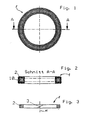
- FIG. 1 consists in a plan view of sealing ring, which is an external view of the outer endless braid layer can be seen, there is, as shown FIGS. 2 and 3 can be seen, from a core ring 2 with joint 3 and designed as Endlosumflechtung 10 wrapping the core ring. 2
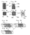
- FIGS. 4A and 4B may be in the material of the core ring, which initially exists as an endless cord and, preferably, already has a polygonal cross-section, a known per se braid, which consists of longitudinal fibers 4A and diagonal braided fibers 4B. Shown in the drawing and insofar preferred is a so-called four-track braiding of the core ring material. As it is for the invention but not on the design of the core material arrives, the core ring in the other drawings is merely schematic, that is not shown as a braid.
- the joint 3 extends obliquely, preferably at 45 ° to the rotary axis axis A. To avoid fraying the interfaces, they can be coated with an adhesive. For the application of the seal in a rotary kiln is suitable for this purpose, a high temperature resistant adhesive, as sold under the trade name PATEX. Thus, the joint can also stick together. To secure the splice this can with a, z. B. fiber reinforced adhesive tape 14 are fixed by wrapping the joint ( Fig. 5A ). Then, on both sides of the joint 3 Ceill.
- Fig. 5B represents in such a way that in the ring extension direction, ie running in the direction of rotation, in particular parallel to each other arranged sewing threads on both sides of the joint 3, the core ring 2, in particular at right angles, penetrate.
- a circumferential sewing between opposing core ring surfaces is provided.
- the Buchentlastungsfäden are arranged in a double position.
- a layer of carbon fibers 5, in particular double-thread carbon fiber yarn is sewn in the manner described above.
- the preferred tensile strength of the carbon fiber threads is between 800 and 1400 N / m 2 .
- These are preferably made of aramid yarn whose tensile strength is preferably between 2,000 and 2,900 Nm 2 per thread.
- the core ring material comparable tensile strength in the joint area of the core ring is achieved, so that a core ring of high dimensional stability is formed.
- the closed core ring produced in this way is then braided in an endless process. This gives the sealing cross section the desired final dimension. Despite this braiding, in which the braiding threads necessarily extend diagonally to the seal circumference, no strains occur and the core ring remains dimensionally stable.
- the two braid layers are in FIGS. 6A to 6C labeled 10a and 10b.
- Formhaltefäden or fibers 8 are stretched along the polygon corners. These are spanned together with the core ring or with an already made braid 10A of the subsequent endless braiding with.
- a tensile force is preferably exerted on the Formhaltefäden, which is higher than the tensile force acting on the braiding threads.
- Out Figure 7a / b is the rotationally driven rotary tube 16 of a known rotary kiln 20 can be seen, at the left mitcardender Stirnend preparation two inventive closed sealing rings 1 in coaxial and coplanar arrangement abut which are rotationally fixed in cross-section matched circular grooves of a Dichtungsstragrings 15 on a fixed end wall 18.
- a calendering of the sealing ring can take place between individual working steps.
- the braiding fibers are finally spliced with the braid present to minimize cross-sectional differences.
Landscapes
- Engineering & Computer Science (AREA)
- General Engineering & Computer Science (AREA)
- Mechanical Engineering (AREA)
- Sealing Devices (AREA)
- Muffle Furnaces And Rotary Kilns (AREA)
- Joints Allowing Movement (AREA)
Claims (22)
- Four tubulaire tournant comportant au moins un joint frontal annulaire fermé entre le tube tournant (16) et les parois frontales fixes (18), selon lequel
au moins ce joint annulaire fermé se compose d'un anneau de base (2), de section polygonale de préférence rectangulaire avec des surfaces de jonction (3) ainsi que d'une gaine réalisée sous la forme d'une tresse périphérique sans fin (10),
caractérisé en ce que
l'anneau de base (2) est fermé dans la zone des surfaces de jonction (3) et il est protégé contre les contraintes de traction par la réunion de ses extrémités. - Four tubulaire tournant selon la revendication 1,
caractérisé en ce que
les surfaces de jonction sont protégées en traction par des fils de reprise de traction (5, 6) ou de fibres s'étendant dans la direction périphérique annulaire et accrochés des deux côtés des surfaces de jonction. - Four tubulaire tournant selon la revendication 1 ou 2,
caractérisé en ce que
la surface de jonction est collée. - Four tubulaire tournant selon l'une des revendications 1 à 3,
caractérisé en ce que
la protection en traction de la surface de jonction de l'anneau de base est réalisée par des fils de couture dirigés dans la direction périphérique annulaire, notamment parallèles entre eux et qui traversent l'anneau de base (2) des deux côtés de la surface de jonction (3). - Four tubulaire tournant selon l'une des revendications 2 à 4,
caractérisé en ce que
les fils de reprise de traction (5) sont notamment des doubles fils de fibres de carbone ayant de préférence une résistance à la traction comprise entre 800 et 1400 N/m2 par fil. - Four tubulaire tournant selon l'une des revendications 1 à 5,
caractérisé en ce que
les fils de reprise de traction (5, 6) sont prévus en une double couche. - Four tubulaire tournant selon la revendication 6,
caractérisé en ce que
les fils de reprise de traction (6) de la couche extérieure (seconde couche) sont des fils d'aramide de préférence avec une résistance à la traction comprise entre 2000 et 2900 N/m2 par fil. - Four tubulaire tournant selon l'une des revendications 1 à 7,
caractérisé en ce que
le tressage périphérique sans fin (10) comporte, dans la zone des arêtes du polygone, des fibres ou des fils de maintien de forme (8), parallèles à la direction périphérique annulaire et notamment des fils de renforcement. - Four tubulaire tournant selon l'une des revendications 1 à 8,
caractérisé en ce que
le tressage périphérique sans fin (10) est à deux couches. - Four tubulaire tournant selon l'une des revendications 1 à 9,
caractérisé en ce que
les extrémités de fils ou de fibres du tressage périphérique sans fin (10) sont intégrées dans le tressage. - Four tubulaire tournant selon l'une des revendications 1 à 10,
caractérisé en ce que
la surface d'assemblage de l'anneau de base (2) est inclinée par rapport à l'axe du tube du four, de préférence à 45°. - Four tubulaire tournant selon l'une des revendications 1 à 11,
caractérisé en ce que
la section de l'anneau de base, au moins dans la zone périphérique des fils de reprise de traction (5, 6), est enroulée de fils de reprise de traction, notamment à fibres de carbone (7). - Joint annulaire fermé pour le joint frontal d'un four tubulaire tournant (20), entre le four tubulaire tournant (16) et les parois frontales fixes (18), composé d'un anneau de base à section polygonale de préférence rectangulaire avec des surfaces de jonction et une enveloppe de l'anneau de base réalisée sous la forme d'un tressage périphérique sans fin,
caractérisé en ce que
la surface de jonction (3) de l'anneau de base (2) est collée et elle est protégée en traction par des fibres ou des fils de décharge en traction (5, 6), s'étendant dans la direction périphérique annulaire et qui sont accrochés des deux côtés de la surface de jonction. - Joint d'étanchéité selon la revendication 13,
caractérisé en ce qu'
il comporte les caractéristiques de l'une des revendications 2 à 10. - Procédé de fabrication d'un joint d'étanchéité annulaire fermé composé d'un noyau de base de section polygonale avec des surfaces de jonction et une gaine de l'anneau de base, réalisée sous la forme d'un tressage périphérique sans fin,
caractérisé en ce que
la surface de jonction de l'anneau de base est tout d'abord collée et ensuite, les fibres ou fils de reprise de traction, sont tendus dans la direction périphérique par-dessus la surface de jonction et sont cousus à l'anneau de base des deux côtés de la surface de jonction. - Procédé selon la revendication 15,
caractérisé en ce que
l'anneau de base est un tressage de fibres à section polygonale, notamment de fibres de carbone non tressées, dirigées longitudinalement. - Procédé selon la revendication 15 ou 16,
caractérisé en ce que
le collage de la surface de jonction est bloqué par l'enroulement à l'aide d'un film ou d'un ruban adhésif, notamment renforcé par des fibres. - Procédé selon les revendications 15 à 17,
caractérisé en ce que
le joint d'étanchéité, le cas échéant également, la matière première de l'anneau de base sont soumis au moins à une étape de fabrication, à une étape de mise en forme donnant la section ou à une étape de maintien de forme, le cas échéant avec compression simultanée, par exemple par calandrage. - Procédé selon l'une des revendications 15 à 18,
caractérisé en ce que
le tressage périphérique sans fin est intégré dans la zone des fils ou des fibres de maintien de forme des arêtes polygonales, en s'étendant dans la direction périphérique annulaire. - Procédé selon la revendication 19,
caractérisé en ce que
les fils de maintien de forme sont installés dans le tressage sans fin. - Procédé selon la revendication 19 ou 20,
caractérisé en ce que
les fils de maintien de forme sont des fibres de carbone, offrant notamment une tenue supérieure à 1400 N/m2. - Procédé selon les revendications 19 à 21,
caractérisé en ce que
les fils de maintien de forme sont tenus pendant le tressage sous une tension plus élevée que celle des fils de tressage.
Applications Claiming Priority (2)
| Application Number | Priority Date | Filing Date | Title |
|---|---|---|---|
| DE10201503 | 2002-01-17 | ||
| DE10201503A DE10201503A1 (de) | 2002-01-17 | 2002-01-17 | Drehrohrofen mit ringförmig geschlossener Stirnenddichtung, ringförmig geschlossene Dichtung für einen Drehrohrofen sowie Verfahren zum Herstellen einer solchen Dichtung |
Publications (3)
| Publication Number | Publication Date |
|---|---|
| EP1329652A2 EP1329652A2 (fr) | 2003-07-23 |
| EP1329652A3 EP1329652A3 (fr) | 2004-01-28 |
| EP1329652B1 true EP1329652B1 (fr) | 2010-04-14 |
Family
ID=7712300
Family Applications (1)
| Application Number | Title | Priority Date | Filing Date |
|---|---|---|---|
| EP03000924A Expired - Lifetime EP1329652B1 (fr) | 2002-01-17 | 2003-01-16 | Four rotatif comportant un joint facial annulaire, joint annulaire pour four rotatif et méthode de fabrication d'un tel joint |
Country Status (5)
| Country | Link |
|---|---|
| US (1) | US6893256B2 (fr) |
| EP (1) | EP1329652B1 (fr) |
| AT (1) | ATE464500T1 (fr) |
| CA (1) | CA2416553C (fr) |
| DE (2) | DE10201503A1 (fr) |
Families Citing this family (6)
| Publication number | Priority date | Publication date | Assignee | Title |
|---|---|---|---|---|
| DE20302000U1 (de) * | 2003-02-08 | 2004-07-08 | Vta Verfahrenstechnik Und Automatisierung Gmbh | Ring-Dichtungsanordnung für einen indirekt beheizten Drehrohrofen |
| US8109009B1 (en) | 2008-07-03 | 2012-02-07 | Collette Jerry R | Air seal for rotary dryer/kiln |
| CN104455437A (zh) * | 2014-12-07 | 2015-03-25 | 无锡高卓流体设备有限公司 | 一种密封圈 |
| CN104455438A (zh) * | 2014-12-07 | 2015-03-25 | 无锡高卓流体设备有限公司 | 一种双端面密封装置 |
| CN107490291A (zh) * | 2017-09-15 | 2017-12-19 | 赵春博 | 一种回转窑双列石墨块密封装置 |
| CN109267229B (zh) * | 2018-09-20 | 2020-10-30 | 慈溪市立基密封制品有限公司 | 一种密封填料及其制备方法和安装方法 |
Family Cites Families (17)
| Publication number | Priority date | Publication date | Assignee | Title |
|---|---|---|---|---|
| DE2338378A1 (de) * | 1973-07-28 | 1975-02-06 | Wegmann & Co | Trittstufenabdeckung fuer mehrstufige einstiege an schienenfahrzeugen, insbesondere reisezugwagen in verbindung mit einer aussenschiebetuer |
| US3976534A (en) | 1973-07-28 | 1976-08-24 | Howaldtswerke-Deutsche Werft Aktiengesellschaft Hamburg Und Kiel | Device for use in uniting the adjacent ends of radially split sealing rings |
| US4212477A (en) * | 1976-03-21 | 1980-07-15 | The United States Of America As Represented By The Administrator Of The National Aeronautics And Space Administration | Circumferential shaft seal |
| US4155559A (en) * | 1977-04-20 | 1979-05-22 | Sieghartner Leonard J | Deformable seal for rotary mechanism |
| US4252352A (en) * | 1980-04-24 | 1981-02-24 | Parker-Hannifin Corporation | Sealing ring |
| DE3127523A1 (de) * | 1981-07-11 | 1983-01-27 | Hecker Werke GmbH & Co. KG Spezialfabriken für Dicht- und Reibelemente, 7031 Weil | Stopfbuchspackung |
| DE3644330A1 (de) * | 1986-12-23 | 1988-07-07 | Burgmann Dichtungswerk Feodor | Dichtung |
| US4932863A (en) * | 1987-09-14 | 1990-06-12 | Anderson Russell W | Heat loss reduction in rotating drum dryers |
| US5221095A (en) * | 1989-06-14 | 1993-06-22 | Inpro Companies, Inc. | Static and dynamic shaft seal assembly |
| DE4035129A1 (de) * | 1990-11-05 | 1992-05-07 | Industriehansa Anlagenbau Gmbh | Gleitringdichtung fuer drehrohrtrommeln |
| GB9101130D0 (en) * | 1991-01-18 | 1991-02-27 | Walker & Co James | Sealing rings |
| US5804316A (en) * | 1993-09-17 | 1998-09-08 | Rm Engineered Products, Inc. | Baked packing for sealing shafts and valve stems |
| DE4343464A1 (de) * | 1993-12-20 | 1995-06-22 | Kloeckner Humboldt Deutz Ag | Hitzebeständige Dichtung |
| BR9400435A (pt) * | 1994-02-04 | 1995-10-17 | Manegro Comercio Ltda | Fita composta para fabricação de gaxetas trançadas gaxeta trançada e processo de formação da referida fita composta |
| DE4433939A1 (de) * | 1994-09-23 | 1995-05-11 | Bernhard Schuette | Ringförmige Endlosdichtung aus fadenförmigen Material |
| US6186510B1 (en) * | 1996-01-30 | 2001-02-13 | Power Packing Company, Inc. | Mechanical contact bearing seal |
| US6325381B1 (en) * | 1999-05-04 | 2001-12-04 | System Seals, Inc. | High-pressure rotary seal |
-
2002
- 2002-01-17 DE DE10201503A patent/DE10201503A1/de not_active Withdrawn
-
2003
- 2003-01-16 CA CA2416553A patent/CA2416553C/fr not_active Expired - Fee Related
- 2003-01-16 EP EP03000924A patent/EP1329652B1/fr not_active Expired - Lifetime
- 2003-01-16 AT AT03000924T patent/ATE464500T1/de active
- 2003-01-16 DE DE50312602T patent/DE50312602D1/de not_active Expired - Lifetime
- 2003-01-17 US US10/346,992 patent/US6893256B2/en not_active Expired - Lifetime
Also Published As
| Publication number | Publication date |
|---|---|
| DE10201503A1 (de) | 2003-10-30 |
| EP1329652A3 (fr) | 2004-01-28 |
| DE50312602D1 (de) | 2010-05-27 |
| US20040086821A1 (en) | 2004-05-06 |
| EP1329652A2 (fr) | 2003-07-23 |
| CA2416553A1 (fr) | 2003-07-17 |
| US6893256B2 (en) | 2005-05-17 |
| CA2416553C (fr) | 2011-05-03 |
| ATE464500T1 (de) | 2010-04-15 |
Similar Documents
| Publication | Publication Date | Title |
|---|---|---|
| EP1738895B1 (fr) | Joint | |
| DE2442335C3 (de) | Verfahren zur Herstellung eines Zahnriemens | |
| EP0150702B1 (fr) | Cordage de fils, filés ou retors issus de matière textile fibreuse | |
| EP0125517B1 (fr) | Câblé de renforcement à fil de guipage | |
| DE60202960T2 (de) | Flacher textilverstärkungsstreifen für leitungen und so verstärkte leitung | |
| DE69412187T2 (de) | Breites Endlosband | |
| DE60026330T2 (de) | Kabel aus parallelen fäden für ein bauwerk, verankerung und verankerungsverfahren für solche kabel | |
| EP0407502A1 (fr) | Cable optique autoporteur. | |
| DE102007049347B4 (de) | Verfahren zur Herstellung eines Vorformlings aus Halbzeug, zur Herstellung eines ringförmigen Rahmenprofils, Verwendung des Vefahrens, sowie Rahmenprofil | |
| EP1112219A1 (fr) | Main courante | |
| AT511080A4 (de) | Sägeseil zur verwendung in einer seilsägemaschine | |
| DE60026214T2 (de) | Strickgarn aus expandiertem Graphit und Stopfbüchsenpackung | |
| DE102015212481A1 (de) | In Längsrichtung endlos geschlossenes Band, insbesondere Rundballenpressband | |
| EP2625325B1 (fr) | Câble de guidage de papier | |
| EP3839287A1 (fr) | Courroie comme moyen de traction sans fin pour bandes transporteuses des presse à balles ou d'enrouleuses de balles | |
| DE10201503A1 (de) | Drehrohrofen mit ringförmig geschlossener Stirnenddichtung, ringförmig geschlossene Dichtung für einen Drehrohrofen sowie Verfahren zum Herstellen einer solchen Dichtung | |
| DE60225517T2 (de) | Strukturmaterial für stopfbüchsenpackung | |
| EP2720840B1 (fr) | Câble de scie destiné à être employé dans une scie à câble | |
| DE60038017T2 (de) | Strickgarn aus expandiertem graphit | |
| DE4141250C2 (de) | Rolle für Rollenherdöfen und Verfahren zu ihrer Herstellung | |
| DE60315318T2 (de) | Material für stopfbuchse und stopfbuchse | |
| EP3124661A1 (fr) | Écartement dynamique de faisceaux de fibres continues pendant un processus de fabrication | |
| DE69723897T2 (de) | Metallkabel für die Verstärkung von Elastomeren | |
| EP1312713B1 (fr) | Enveloppe cylindrique | |
| DE69303256T2 (de) | Geflochtener Graphit-Folieverbund und Verfahren zUr Verwendung |
Legal Events
| Date | Code | Title | Description |
|---|---|---|---|
| PUAI | Public reference made under article 153(3) epc to a published international application that has entered the european phase |
Free format text: ORIGINAL CODE: 0009012 |
|
| AK | Designated contracting states |
Designated state(s): AT BE BG CH CY CZ DE DK EE ES FI FR GB GR HU IE IT LI LU MC NL PT SE SI SK TR |
|
| AX | Request for extension of the european patent |
Extension state: AL LT LV MK RO |
|
| PUAL | Search report despatched |
Free format text: ORIGINAL CODE: 0009013 |
|
| AK | Designated contracting states |
Kind code of ref document: A3 Designated state(s): AT BE BG CH CY CZ DE DK EE ES FI FR GB GR HU IE IT LI LU MC NL PT SE SI SK TR |
|
| AX | Request for extension of the european patent |
Extension state: AL LT LV MK RO |
|
| RIC1 | Information provided on ipc code assigned before grant |
Ipc: 7F 16J 15/34 A Ipc: 7F 16J 15/22 B |
|
| 17P | Request for examination filed |
Effective date: 20040508 |
|
| AKX | Designation fees paid |
Designated state(s): AT BE BG CH CY CZ DE DK EE ES FI FR GB GR HU IE IT LI LU MC NL PT SE SI SK TR |
|
| RAP1 | Party data changed (applicant data changed or rights of an application transferred) |
Owner name: VTA VERFAHRENSTECHNIK UND AUTOMATISIERUNG GMBH |
|
| 17Q | First examination report despatched |
Effective date: 20071108 |
|
| GRAP | Despatch of communication of intention to grant a patent |
Free format text: ORIGINAL CODE: EPIDOSNIGR1 |
|
| GRAS | Grant fee paid |
Free format text: ORIGINAL CODE: EPIDOSNIGR3 |
|
| GRAA | (expected) grant |
Free format text: ORIGINAL CODE: 0009210 |
|
| AK | Designated contracting states |
Kind code of ref document: B1 Designated state(s): AT BE BG CH CY CZ DE DK EE ES FI FR GB GR HU IE IT LI LU MC NL PT SE SI SK TR |
|
| REG | Reference to a national code |
Ref country code: GB Ref legal event code: FG4D Free format text: NOT ENGLISH |
|
| REG | Reference to a national code |
Ref country code: CH Ref legal event code: EP |
|
| REG | Reference to a national code |
Ref country code: IE Ref legal event code: FG4D Free format text: LANGUAGE OF EP DOCUMENT: GERMAN |
|
| REF | Corresponds to: |
Ref document number: 50312602 Country of ref document: DE Date of ref document: 20100527 Kind code of ref document: P |
|
| RAP2 | Party data changed (patent owner data changed or rights of a patent transferred) |
Owner name: BP EUROPA SE |
|
| REG | Reference to a national code |
Ref country code: NL Ref legal event code: VDEP Effective date: 20100414 |
|
| REG | Reference to a national code |
Ref country code: FR Ref legal event code: TP |
|
| PG25 | Lapsed in a contracting state [announced via postgrant information from national office to epo] |
Ref country code: ES Free format text: LAPSE BECAUSE OF FAILURE TO SUBMIT A TRANSLATION OF THE DESCRIPTION OR TO PAY THE FEE WITHIN THE PRESCRIBED TIME-LIMIT Effective date: 20100725 Ref country code: NL Free format text: LAPSE BECAUSE OF FAILURE TO SUBMIT A TRANSLATION OF THE DESCRIPTION OR TO PAY THE FEE WITHIN THE PRESCRIBED TIME-LIMIT Effective date: 20100414 Ref country code: SE Free format text: LAPSE BECAUSE OF FAILURE TO SUBMIT A TRANSLATION OF THE DESCRIPTION OR TO PAY THE FEE WITHIN THE PRESCRIBED TIME-LIMIT Effective date: 20100414 |
|
| REG | Reference to a national code |
Ref country code: IE Ref legal event code: FD4D |
|
| PG25 | Lapsed in a contracting state [announced via postgrant information from national office to epo] |
Ref country code: SI Free format text: LAPSE BECAUSE OF FAILURE TO SUBMIT A TRANSLATION OF THE DESCRIPTION OR TO PAY THE FEE WITHIN THE PRESCRIBED TIME-LIMIT Effective date: 20100414 Ref country code: FI Free format text: LAPSE BECAUSE OF FAILURE TO SUBMIT A TRANSLATION OF THE DESCRIPTION OR TO PAY THE FEE WITHIN THE PRESCRIBED TIME-LIMIT Effective date: 20100414 |
|
| PG25 | Lapsed in a contracting state [announced via postgrant information from national office to epo] |
Ref country code: CY Free format text: LAPSE BECAUSE OF FAILURE TO SUBMIT A TRANSLATION OF THE DESCRIPTION OR TO PAY THE FEE WITHIN THE PRESCRIBED TIME-LIMIT Effective date: 20100414 Ref country code: GR Free format text: LAPSE BECAUSE OF FAILURE TO SUBMIT A TRANSLATION OF THE DESCRIPTION OR TO PAY THE FEE WITHIN THE PRESCRIBED TIME-LIMIT Effective date: 20100715 |
|
| PG25 | Lapsed in a contracting state [announced via postgrant information from national office to epo] |
Ref country code: PT Free format text: LAPSE BECAUSE OF FAILURE TO SUBMIT A TRANSLATION OF THE DESCRIPTION OR TO PAY THE FEE WITHIN THE PRESCRIBED TIME-LIMIT Effective date: 20100816 Ref country code: EE Free format text: LAPSE BECAUSE OF FAILURE TO SUBMIT A TRANSLATION OF THE DESCRIPTION OR TO PAY THE FEE WITHIN THE PRESCRIBED TIME-LIMIT Effective date: 20100414 Ref country code: DK Free format text: LAPSE BECAUSE OF FAILURE TO SUBMIT A TRANSLATION OF THE DESCRIPTION OR TO PAY THE FEE WITHIN THE PRESCRIBED TIME-LIMIT Effective date: 20100414 Ref country code: IE Free format text: LAPSE BECAUSE OF FAILURE TO SUBMIT A TRANSLATION OF THE DESCRIPTION OR TO PAY THE FEE WITHIN THE PRESCRIBED TIME-LIMIT Effective date: 20100414 |
|
| PLBE | No opposition filed within time limit |
Free format text: ORIGINAL CODE: 0009261 |
|
| STAA | Information on the status of an ep patent application or granted ep patent |
Free format text: STATUS: NO OPPOSITION FILED WITHIN TIME LIMIT |
|
| PG25 | Lapsed in a contracting state [announced via postgrant information from national office to epo] |
Ref country code: SK Free format text: LAPSE BECAUSE OF FAILURE TO SUBMIT A TRANSLATION OF THE DESCRIPTION OR TO PAY THE FEE WITHIN THE PRESCRIBED TIME-LIMIT Effective date: 20100414 Ref country code: CZ Free format text: LAPSE BECAUSE OF FAILURE TO SUBMIT A TRANSLATION OF THE DESCRIPTION OR TO PAY THE FEE WITHIN THE PRESCRIBED TIME-LIMIT Effective date: 20100414 |
|
| 26N | No opposition filed |
Effective date: 20110117 |
|
| BERE | Be: lapsed |
Owner name: VTA VERFAHRENSTECHNIK UND AUTOMATISIERUNG G.M.B.H. Effective date: 20110131 |
|
| PG25 | Lapsed in a contracting state [announced via postgrant information from national office to epo] |
Ref country code: MC Free format text: LAPSE BECAUSE OF NON-PAYMENT OF DUE FEES Effective date: 20110131 |
|
| REG | Reference to a national code |
Ref country code: CH Ref legal event code: PL |
|
| PG25 | Lapsed in a contracting state [announced via postgrant information from national office to epo] |
Ref country code: LI Free format text: LAPSE BECAUSE OF NON-PAYMENT OF DUE FEES Effective date: 20110131 Ref country code: CH Free format text: LAPSE BECAUSE OF NON-PAYMENT OF DUE FEES Effective date: 20110131 |
|
| PG25 | Lapsed in a contracting state [announced via postgrant information from national office to epo] |
Ref country code: BE Free format text: LAPSE BECAUSE OF NON-PAYMENT OF DUE FEES Effective date: 20110131 |
|
| REG | Reference to a national code |
Ref country code: DE Ref legal event code: R082 Ref document number: 50312602 Country of ref document: DE Representative=s name: BJOERN MANN, DE Ref country code: DE Ref legal event code: R082 Ref document number: 50312602 Country of ref document: DE Representative=s name: MANN, BJOERN, DE Ref country code: DE Ref legal event code: R082 Ref document number: 50312602 Country of ref document: DE Representative=s name: GROSSE, SCHUMACHER, KNAUER, VON HIRSCHHAUSEN, DE |
|
| PG25 | Lapsed in a contracting state [announced via postgrant information from national office to epo] |
Ref country code: LU Free format text: LAPSE BECAUSE OF NON-PAYMENT OF DUE FEES Effective date: 20110116 |
|
| REG | Reference to a national code |
Ref country code: FR Ref legal event code: CA Effective date: 20130729 |
|
| PG25 | Lapsed in a contracting state [announced via postgrant information from national office to epo] |
Ref country code: BG Free format text: LAPSE BECAUSE OF FAILURE TO SUBMIT A TRANSLATION OF THE DESCRIPTION OR TO PAY THE FEE WITHIN THE PRESCRIBED TIME-LIMIT Effective date: 20100714 Ref country code: TR Free format text: LAPSE BECAUSE OF FAILURE TO SUBMIT A TRANSLATION OF THE DESCRIPTION OR TO PAY THE FEE WITHIN THE PRESCRIBED TIME-LIMIT Effective date: 20100414 |
|
| REG | Reference to a national code |
Ref country code: GB Ref legal event code: 732E Free format text: REGISTERED BETWEEN 20130912 AND 20130918 |
|
| PG25 | Lapsed in a contracting state [announced via postgrant information from national office to epo] |
Ref country code: HU Free format text: LAPSE BECAUSE OF FAILURE TO SUBMIT A TRANSLATION OF THE DESCRIPTION OR TO PAY THE FEE WITHIN THE PRESCRIBED TIME-LIMIT Effective date: 20100414 |
|
| REG | Reference to a national code |
Ref country code: FR Ref legal event code: PLFP Year of fee payment: 14 |
|
| REG | Reference to a national code |
Ref country code: FR Ref legal event code: PLFP Year of fee payment: 15 |
|
| REG | Reference to a national code |
Ref country code: DE Ref legal event code: R082 Ref document number: 50312602 Country of ref document: DE Representative=s name: GROSSE, SCHUMACHER, KNAUER, VON HIRSCHHAUSEN, DE |
|
| REG | Reference to a national code |
Ref country code: DE Ref legal event code: R082 Ref document number: 50312602 Country of ref document: DE Representative=s name: GROSSE, SCHUMACHER, KNAUER, VON HIRSCHHAUSEN, DE Ref country code: DE Ref legal event code: R081 Ref document number: 50312602 Country of ref document: DE Owner name: VTA VERFAHRENSTECHNIK UND AUTOMATISIERUNG GMBH, DE Free format text: FORMER OWNER: BP EUROPA SE, 20457 HAMBURG, DE |
|
| REG | Reference to a national code |
Ref country code: FR Ref legal event code: PLFP Year of fee payment: 16 |
|
| REG | Reference to a national code |
Ref country code: DE Ref legal event code: R082 Ref document number: 50312602 Country of ref document: DE Representative=s name: GROSSE, SCHUMACHER, KNAUER, VON HIRSCHHAUSEN, DE |
|
| REG | Reference to a national code |
Ref country code: AT Ref legal event code: PC Ref document number: 464500 Country of ref document: AT Kind code of ref document: T Owner name: VTA VERFAHRENSTECHNIK UND AUTOMATISIERUNG GMBH, DE Effective date: 20180403 |
|
| REG | Reference to a national code |
Ref country code: FR Ref legal event code: TP Owner name: VTA VERFAHRENSTECHNIK UND AUTOMATISIERUNG GMBH, DE Effective date: 20180625 |
|
| REG | Reference to a national code |
Ref country code: GB Ref legal event code: 732E Free format text: REGISTERED BETWEEN 20181011 AND 20181017 |
|
| PGFP | Annual fee paid to national office [announced via postgrant information from national office to epo] |
Ref country code: DE Payment date: 20190329 Year of fee payment: 17 Ref country code: FR Payment date: 20190123 Year of fee payment: 17 Ref country code: IT Payment date: 20190121 Year of fee payment: 17 Ref country code: GB Payment date: 20190124 Year of fee payment: 17 |
|
| PGFP | Annual fee paid to national office [announced via postgrant information from national office to epo] |
Ref country code: AT Payment date: 20190118 Year of fee payment: 17 |
|
| REG | Reference to a national code |
Ref country code: DE Ref legal event code: R119 Ref document number: 50312602 Country of ref document: DE |
|
| REG | Reference to a national code |
Ref country code: AT Ref legal event code: MM01 Ref document number: 464500 Country of ref document: AT Kind code of ref document: T Effective date: 20200116 |
|
| GBPC | Gb: european patent ceased through non-payment of renewal fee |
Effective date: 20200116 |
|
| PG25 | Lapsed in a contracting state [announced via postgrant information from national office to epo] |
Ref country code: GB Free format text: LAPSE BECAUSE OF NON-PAYMENT OF DUE FEES Effective date: 20200116 Ref country code: FR Free format text: LAPSE BECAUSE OF NON-PAYMENT OF DUE FEES Effective date: 20200131 Ref country code: DE Free format text: LAPSE BECAUSE OF NON-PAYMENT OF DUE FEES Effective date: 20200801 |
|
| PG25 | Lapsed in a contracting state [announced via postgrant information from national office to epo] |
Ref country code: AT Free format text: LAPSE BECAUSE OF NON-PAYMENT OF DUE FEES Effective date: 20200116 |
|
| PG25 | Lapsed in a contracting state [announced via postgrant information from national office to epo] |
Ref country code: IT Free format text: LAPSE BECAUSE OF NON-PAYMENT OF DUE FEES Effective date: 20200116 |