EP1329691A2 - Procédé et dispositif pour la localisation automatique de cibles - Google Patents
Procédé et dispositif pour la localisation automatique de cibles Download PDFInfo
- Publication number
- EP1329691A2 EP1329691A2 EP03002934A EP03002934A EP1329691A2 EP 1329691 A2 EP1329691 A2 EP 1329691A2 EP 03002934 A EP03002934 A EP 03002934A EP 03002934 A EP03002934 A EP 03002934A EP 1329691 A2 EP1329691 A2 EP 1329691A2
- Authority
- EP
- European Patent Office
- Prior art keywords
- target
- fan
- receiving unit
- signals
- unit
- Prior art date
- Legal status (The legal status is an assumption and is not a legal conclusion. Google has not performed a legal analysis and makes no representation as to the accuracy of the status listed.)
- Granted
Links
Images


Classifications
-
- G—PHYSICS
- G01—MEASURING; TESTING
- G01C—MEASURING DISTANCES, LEVELS OR BEARINGS; SURVEYING; NAVIGATION; GYROSCOPIC INSTRUMENTS; PHOTOGRAMMETRY OR VIDEOGRAMMETRY
- G01C15/00—Surveying instruments or accessories not provided for in groups G01C1/00 - G01C13/00
- G01C15/002—Active optical surveying means
Definitions
- the invention relates to a method for automatic detection a target according to the preamble of the claim 1, a device according to the preamble of claim 11, a receiving unit according to the preamble of claim 19, a geodetic measuring device according to the preamble of the claim 23 and geodetic surveying systems according to claim 25 or 26.
- Optoelectronic devices for automatic detection and localization of geodetic targets for example a retroreflector or a reflective tape, are accordingly already in various forms used.
- Complement devices of this type thereby the ones used for geodetic surveying tasks sensory measuring equipment, in particular provides the Combination with a motorized theodolite with automatic Target acquisition has significant advantages.
- Devices for finding target marks and thus also the invention relates in a broader sense to all measuring devices, the directives to be handled directly by humans be optically aligned to measuring points.
- geometric measuring device is intended in this context generally understood a measuring instrument be that about devices for measurement or verification of data with spatial reference or also serves for alignment. This particularly concerns the measurement from distance and / or direction or the angles to a reference or measurement point. Beyond that, however still other devices, e.g. Components for satellite-based Location determination (e.g. GPS or GLONASS), available be used for measurements according to the invention can be.
- the automated theodolites in use today are not only with angle and distance sensors but also with an optoelectronic Target search, positioning and target point measuring device, in the following automatic target acquisition unit Called (AZE).
- AZE automatic target acquisition unit Called
- Such theodolites are able to automatically move to the destination and to measure the spatial coordinates. In the case of integrity is the time saving with such automated Instruments considerably. If the system is also via remote control, for example, from the target point as a one-man station operable, so is the work done and with it achieved cost savings even more pronounced.
- AZE An integral part of these automated surveying instruments is the AZE.
- Various solutions are known such as CCD or CMOS cameras with image processing, optoelectronic position sensitive semiconductor detectors (PSD), 4 quadrant diodes, acousto-optical beam scanners etc.
- a major disadvantage of a small sensor field of view is the difficult goal search, because the measuring target at the beginning of a measurement often outside of the visual field. In many applications, especially in the short-distance range, with which a wide-angle The field of work involved has an extensive scope Sensor field of view advantages.
- the sensor searches for one programmed algorithm or procedure the target independently, but this takes time because of the small field of vision
- the search field is replaced by the User defined so that the target object search is more targeted and takes less time, but this has the Disadvantage that the search field configuration with every change of location must be reprogrammed.
- CH 676 042 is a device with fan-like transmitter and receiver known, which in one rotatable measuring head is housed. From the sending unit light pulses are emitted in a light fan, which reflected pulses are regarding angle information evaluated accordingly.
- this device has the considerable disadvantage, not only the target objects to be measured but also to approach foreign, disturbing objects. Such objects are, among other things, optically reflective Objects, like shop windows or traffic signs, however also reflected sunlight on motor vehicles.
- a continuation of the above target search device for the rough Determination of the target coordinates is described in CH676041. It is combined with an optoelectronic Device for fine measurement.
- the real one Target search device spans two perpendicular to each other Subjects with which the location of the target point is two-dimensional is roughly measured, the subsequent fine measurement the second device can then be used without a destination search be performed.
- the disadvantage of this combination is also the lack of robustness in relation to one incorrect enticing to foreign objects.
- a motorized theodolite, the equipped with a sensor for detecting the target point coordinates is composed of one or two fan-like Transmission bundles and two optical reception channels.
- a special feature this device is that the optical Triaxial axes of the transmission channel and the two receivers lie in one plane, this enables one Panning or searching movement of the theodolite makes the distinction of normal reflective and retroreflective Objects by evaluating the chronological order of the two Receive signals.
- This method of pupil division on the receiver side has the disadvantage, however, that this distinguishing feature only exists at short distances, moreover is the device is expensive because of the two reception channels or expensive.
- a major disadvantage of all previously known devices is insufficient robustness against highly reflective Foreign objects that are mistakenly interpreted as the target object as well as disruption or at least delay the search process due to strong sunlight or sun reflections.
- the search process is done manually Radiotelephony or data radio supported.
- a additional optical receiver unit attached to the target object checked whether the theodolite's search beam Target object hits. If a corresponding search signal is received, the target object reports its identification via radio data transmission on the theodolites. While this solution is robust, but affects the ergonomics of the target object.
- the objects of the present invention are Improvement of the sensor devices defined at the beginning.
- One task is a geodetic measuring device to provide rough target search that with regard to the fastest possible localization and identification of target objects and their determination of the rough coordinates is suitable and that a shorter search time for a Has a range of up to 1000m.
- the search for a target is a main problem since requires a large sensor field of view, correspondingly large fan angle is reached. With bigger however, the fan angle decreases the range. It is therefore the object of the invention to cover the range of geodetic applications and at the same time one to achieve high search speed.
- Another task is to enable a search process compared to extraneous light and self-reflexes at external targets is robust.
- the search process must not go through Foreign targets with a high degree of reflection or through objects be delayed or interrupted with solar reflex.
- the task involves simultaneous identification of the target objects to be measured using suitable identification features even during the search.
- the present invention relates essentially to an optoelectronic Target search device consisting of a fan-like Send channel, which is the target to be located irradiated, a fan-like receiving channel, which the receives light reflected from the target object, a motorized one Measuring device, for example a theodolite, which around one of the two axes during the search moved, at least one electronic evaluation unit Determination of the rough target point position, signal strength of the reflected Signal, the extent of the target in Scan direction, and the distance to the target object. Optionally can also recorded the duration of the reflected optical signal become.
- Both the levels of the two optoelectronic light fans as well as the axis of rotation of the theodolite are oriented parallel to each other.
- Hereinafter are supposed to be the terms of horizontal and vertical movement to be understood in such a way that with a movement always a corresponding component and a corresponding movement available.
- a horizontal movement of the transmitter unit can therefore also in particular by one movement inclined to the horizon can be achieved.
- a powerful and sensory sensitive transit time meter serves as a destination search device. Suitable time meter with pulse modulation have a long range and short measuring time.
- the achievable optical transmission powers with the pulse laser diodes, which are only millimeters in size are over 100 watts. This also allows fan-like expansion of the transmission beam the required Realize ranges for geodetic applications.
- the transmitter emits optical pulses at a rate in the kHz range. Since the device in Single shot evaluation process is information over the scanned environment in the nanosecond to Microsecond range available.
- the received impulses are scanned with a fast AD converter, thereby an intensity picture of the surroundings is created.
- the sampled pulses for example in a 2D memory filed and subsequently evaluated or it an initial analysis and further evaluation are carried out promptly is based on these first results, e.g. a Accumulation or contraction of the impulses can be.
- the dimensioning of the optical transmission fan is dimensioned in such a way that this is the typical environment to be measured covers in the vertical direction.
- the divergence in vertical Diffraction direction is preferably limited narrow.
- the robustness against sun reflecting surfaces and reflecting foreign goals is improved according to the invention or only reached. Because of the strong laser pulses are sun reflecting surfaces in 2-dimensional Intensity image not visible for two reasons. First the laser radiation from the transmitter is spectrally narrow and permitted a comparatively narrow interference filter in the receive beam path, sunlight is largely blocked. Second, the pulse lasers generate strong flashes of light, whose radiance is greater than that of solar reflections. A robustness against sun reflecting This achieves surfaces.
- the correct target objects must be from those contained in the 2-dimensional intensity image Objects are identified according to the invention.
- Each target type generates a characteristic signal curve a characteristic extension as well Function of the distance.
- Target identification is therefore possible using the two distance-dependent measurement curves.
- at the measured respective object distance is checked whether Object extension and signal strength in the tolerance band of the sought Are the target.
- a comparison with only one limit value, e.g. a comparison against the lower limit regarding the signal and against the upper limit regarding the object size.
- the instrument is installed immediately first scanned the entire area. This creates a 2-dimensional intensity image, which contains all highly reflective objects.
- the coordinates of the irrelevant target objects such as Störund Foreign goals are calculated and saved. With the Knowledge of the coordinates of all interfering objects and foreign targets can be hidden from all other searches become. This saves additional search time, because the objects that are not relevant for the measurement task are sensory no longer exist.
- the target object If a target object is found, then there is a distance and a direction coordinate known. Next is the second spatial direction measured. This is done according to the well-known search procedure with the automated in the theodolite Target acquisition unit (AZE) implemented.
- AZE the automated in the theodolite Target acquisition unit
- the AZE search and In this case the measuring process is very efficient and fast, since only one-dimensional movement or driving is required.
- the combination of the two devices creates an additional one Use. Because the AZE is the position of the target accurate to the second of an angle are at the end of the AZE search and Measuring process the target point coordinates not only roughly, but with geodetic accuracy in the mm to submm range known.
- the combination of the target search device according to the invention with an automated target acquisition unit (AZE) thus the complete and mm-precise determination of the 3D coordinates of target objects.
- An essential property of the method according to the invention or the device is the speed of the search process.
- One difficulty is the great one, because of the geodetic distance range given signal dynamics.
- this task supported or resolved by measures on the transmitter side.
- the Great signal dynamics can be achieved by sending out several laser pulses different intensity are intercepted.
- the This divides signal dynamics between transmitter and receiver. In the short distance range the weak pulses with a smaller amplitude and in the long distance range the strong pulses are evaluated with high amplitude.
- a suitable use of the device according to the invention represents the modular integration in a motorized Theodolite with automatic target acquisition unit (AZE) according to Patent US 6,031,606.
- AZE automatic target acquisition unit
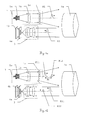
- Fig.1a is arranged in the transmitter unit 1 Pulse laser diode 1a as a transmitter diode with pulse modulation electromagnetic Radiation with pulses P1 generated as a signal.
- a suitable pulse duration is 50, for example Nanoseconds.
- the strong signals generated by this with optical performance in the watt range are robust against Ambient light reflections. Even sunlit reflecting surfaces are therefore weaker than the received signal pulse.
- the radiation generated is oriented in a vertically Fan emitted, the device side by a combination from a lens 1b and a cylindrical lens array 1c is produced.
- a lens 1b and a cylindrical lens array 1c is produced.
- Components are used, e.g. Microlens arrays or diffractive optical elements.
- the fan-like field of view becomes the receiver side through a slit diaphragm 4a in front of a receiving diode photosensitive element 4b together with a lens 3 realized with a cylindrical effect.
- FIG. 1b In the second implementation form shown in FIG. 1b are the same on the device side in the transmission unit 1 Components of pulse laser diode 1a, lens 1b and cylindrical lens array 1c used.
- the pulse rate is in the kHz range.
- the emitted radiation now has a pulse P11 with a larger one and a pulse P12 with a lower maximum pulse height, which follow one another in time and thus in this form of realization represent a double pulse.
- the reflected pulses P21 and P22 detected by the receiving unit. This exists again from a lens 3 with a cylindrical effect and a slit diaphragm 4a in front of a receiving diode as photosensitive Element 4b.
- the one in the reception dynamic range of the recipient When receiving the impulses of different intensity evaluated the one in the reception dynamic range of the recipient.
- This example is for a shorter one Measuring distance, the limit of which is, for example, 20 m can, the reflected pulse P22 with low pulse height and for a larger measuring distance the reflected pulse P21 used with a larger pulse height.
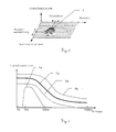
- FIG 2 is a section of a two-dimensional schematic Intensity image shown with target object.
- the individual signal pulses 5 detected by the receiver depending on the time of their issue with time resolved sampling detected. With every laser pulse Another signal track is created along the intensity image the distance axis. With the time-resolved sampling there is an assignment with regard to the distance, and the Emission times determine the horizontal angle belonging to the signal track firmly.
- the signal-distance model forms the basis of the plausibility check and the object width-distance model (tolerance value tables).
- the object width or extent is based on the product of pulse number and angular velocity calculated. There is also a consideration or calculation of the reflectance of the target object possible.
- the extent of the object is an important identifier, since traffic signs consistently compared to the actual ones Target marks, have large reflective surface.
- object-specific characteristics there can be one for each target type own, specific tolerance value table. there can also freely select a tolerance table for special, user-specific target types are used.
- Alternative or additional plausibility checks can also be carried out based on other criteria. For example can be spectrally different if necessary Reflectivity of different objects analyzed become.
- FIG. 3 shows an example of a plausibility check regarding the signal amplitude using a Plausibility band (tolerance value table).
- the plausibility check is done by checking whether a measured Value of a target within a plausibility band lies, which by a lower tolerance limit 8a and an upper tolerance limit 8b is defined.
- the theoretical The curve of all values of a target is determined by the distance Profile 7a shown. For example would like a value for a foreign target on its profile for example the profile 6a of a traffic sign, and thus outside of the plausibility band and thus as Foreign target can be identified.
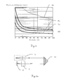
- FIG.4 Another plausibility check procedure regarding the apparent object size, again using a plausibility band (tolerance value table) shown in Fig.4.
- a tolerance value table is shown, which is the apparent object width in units of time with logarithmic scale for a horizontal scan of the Includes measuring device for the different distances, in which a target can be found.
- Also here is a check whether the measured value is within by the lower tolerance limit 8c and the upper tolerance limit 8d defined plausibility band. On Value for a foreign target would be on or in the Close to its theoretical profile 6b and thus outside of the plausibility band.
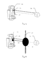
- 5a-b show the conditions in the reflection of the emitted pulses on a retroreflector compared to Reflection on a foreign target for the close range.
- Fig.5a the reflection on a retroreflector is shown schematically 2a shown in the vicinity.
- the Radiation emitted by the transmitter unit 1 is emitted by the retroreflector 2a reflected parallel offset and can thus in the axis defined by lens 3 and detector 4 of the receiving unit.
- Fig. 5b The deviating situation with the reflection on one Foreign target 2b is shown in Fig. 5b.
- the foreign goal does not lead to a parallel offset from that of the transmission unit 1 emitted radiation, so this is not in the through Objective 3 and detector 4 defined axis recorded can be.
- a biaxial arrangement of the visual fields of Sending unit 1 and receiving unit thus enable suppression an acquisition of external targets for the close range.
- the fan-shaped Field of vision can be divided into several sectors alternatively, several subjects can be placed side by side be used.
- the Figures 6a-c show accordingly alternative embodiments of an inventive Receiver unit with structured compartments, horizontal Tuft of fans and two-dimensional structured field of vision.
- the sensor fan is on the receiving side divided into segments. This creates a rough spatial Position determination also possible in the direction of the subject.
- FIG. 6a shows the structuring of the fan of the receiving unit.
- the one emitted by the transmitter unit 1 and one Retroreflector 2a reflected radiation is now transmitted through a division of the receiving fan with additional location information receive.
- This division of the fan 9a can be divided into several sectors by a slit diaphragm 11a in the first focal point of the cylindrical receiver optics.
- a switchable slot cover can be used for optionally the transmission of the relevant slot can be changed.
- the photosensitive element 12a is placed in the area of the second focal plane to the visual field the receiving optics 10 perpendicular in the spatial direction to cover fan with high transmission.
- the slit aperture 11a becomes the receiving fan in, for example 3 sectors divided, which is a rough position measurement also in the vertical direction.
- the one from the retroreflector 2a coming radiation happens in the shown Example the middle opening of the slit diaphragm 11a, see above that a rough estimate of the angular range in vertical Direction can take place.
- FIG. 6b shows several compartments.
- the production several receiving compartments arranged side by side as a fan cluster 9b is carried out by using a structured photosensitive receiving surface 12b in the second focal plane, especially in connection with a slot diaphragm 11b structured in the same arrangement.
- This division of the photosensitive receiving surface 12b e.g. in a linear array of photodetectors the clump of search subjects lying side by side.
- another number of subjects can be selected by choosing a suitable subdivision cause.
- tufts are also included two or four compartments possible.
- the middle fan of this example which is parallel to the transmission axis, reacts to the retroreflector 2a, which is towards the transmission axis inclined fan reacts to objects with single mirroring, the third subject only on sun reflections.
- a structured one photosensitive receiving surface 12b therefore increases the Security regarding correct identification reflective Objects.
- a receiving unit according to the invention with two-dimensional Structuring of the visual field is shown in Fig.6c.
- the receiving optics 10 with radiation detected in their visual field is transmitted via a Beam splitter 13 directed to two different detectors.
- the first detector consists of a vertically structured one photosensitive receiving surface 12b and a corresponding Slit aperture 11b in the second focal plane.
- the second detector consists of a horizontally structured one photosensitive receiving surface 12c with associated Slit aperture 11c in the first focal plane.
- photosensitive elements 12a or Receiving surfaces 12b and 12c can be of any suitable shape of location-sensitive detectors such as Receiving diodes or Receive diode arrays or PSD can be used.
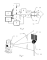
- Fig. 7a-b the combination of an inventive Device 15 with an AZE system 16 together with the schematic sequence of the method is shown.
- FIG. 7 a shows the structural integration of an inventive one Device 15 and an AZE system into a geodetic Measuring device 14. This complements the inventive Device 15 as, for example, in a theodolite geodesic measuring device 14 already existing AZE system 16.
- the emission to recognize a retroreflector 2a as Target mark by the device 15 and AZE system according to the invention 16 takes place in this example essentially in parallel to each other.
- FIG. 7b shows the combination of the two searches shown schematically.
- the device according to the invention 15 there is a quick environmental scan with a vertical one Compartments 17 for determining the horizontal angle one Target.
- a Retroreflector 2a found as target and its location roughly determined.
- the measurement data of the device according to the invention 15 can be used to support other sensors be forwarded in the geodetic measuring device 14, for example to an AZE system 16.
- This AZE system 16 searches for the retroreflector with his fan 18 2a and thus also determines the vertical angle.
- There is a channel separation to other optical sensors by means of suitable optical carrier wavelengths, a simultaneous use of several sensors in the geodetic measuring device or several geodetic measuring devices.
- a system clock A serves as a common time base, with the image memory I, the electronic evaluation unit C, the control and signal processing unit B, the Analog-to-digital converter H and the laser driver and controller E is connected.
- the laser F emits radiation that via a beam-shaping optics 19 onto a retroreflector is sent. After the reflection has taken place, it becomes Receive radiation and via an image-forming mask 20 the detector G directed.
- the signal of this detector G is converted by the analog-to-digital converter H and in the electronic Processing unit C further processed.
- This is connected to the control and signal processing unit B, the image memory I and the tolerance value tables J for all possible target types. Via an interface there is the possibility of a connection to one other system D, e.g. a geodetic measuring device or the evaluation unit of a turning device.
- FIG. 9 shows a geodetic surveying system according to the invention with automatic target recognition based on of a barcode pattern on the target mark.
- the target marking which are exemplarily designed as a retroreflector 2a is additionally attached a coded target plate 22.
- the coding consists of optically highly reflective Stripes, which are scanned sequentially during a search become.
- the vertical compartments 17 make one sufficient large vertical angle swept over so that parallel illumination or detection of target plate 22 and retroreflector 2a is possible.
- the one received by the search sensor The signal is amplitude modulated in time, the code the target plate is transformed into a chronological sequence. The result is a very quick target search and identification of the target mark possible.
- By means of a Coordinate database certain target marks, but also hide disruptive objects. Such points are not approached.
- the data image is next to the object distance and object size also the coded information of the target plate.
Landscapes
- Physics & Mathematics (AREA)
- Engineering & Computer Science (AREA)
- General Physics & Mathematics (AREA)
- Radar, Positioning & Navigation (AREA)
- Remote Sensing (AREA)
- Optical Radar Systems And Details Thereof (AREA)
- Radar Systems Or Details Thereof (AREA)
Priority Applications (1)
| Application Number | Priority Date | Filing Date | Title |
|---|---|---|---|
| EP20030002934 EP1329691B1 (fr) | 2002-01-22 | 2003-01-16 | Procédé et dispositif pour la localisation automatique de cibles |
Applications Claiming Priority (3)
| Application Number | Priority Date | Filing Date | Title |
|---|---|---|---|
| EP02001487 | 2002-01-22 | ||
| EP02001487A EP1329690A1 (fr) | 2002-01-22 | 2002-01-22 | Procédé et dispositif pour la localisation automatique de cibles |
| EP20030002934 EP1329691B1 (fr) | 2002-01-22 | 2003-01-16 | Procédé et dispositif pour la localisation automatique de cibles |
Publications (3)
| Publication Number | Publication Date |
|---|---|
| EP1329691A2 true EP1329691A2 (fr) | 2003-07-23 |
| EP1329691A3 EP1329691A3 (fr) | 2009-05-27 |
| EP1329691B1 EP1329691B1 (fr) | 2014-03-26 |
Family
ID=26077569
Family Applications (1)
| Application Number | Title | Priority Date | Filing Date |
|---|---|---|---|
| EP20030002934 Expired - Lifetime EP1329691B1 (fr) | 2002-01-22 | 2003-01-16 | Procédé et dispositif pour la localisation automatique de cibles |
Country Status (1)
| Country | Link |
|---|---|
| EP (1) | EP1329691B1 (fr) |
Cited By (7)
| Publication number | Priority date | Publication date | Assignee | Title |
|---|---|---|---|---|
| DE102006060062A1 (de) * | 2006-12-19 | 2008-07-03 | Sick Ag | Objektfeststellungssensor |
| EP2006633A3 (fr) * | 2007-06-20 | 2009-01-14 | Mitutoyo Corporation | Interféromètre laser de suivi et son procédé de réinitialisation |
| CN101738202B (zh) * | 2009-12-22 | 2011-12-28 | 中国科学院长春光学精密机械与物理研究所 | 光电经纬仪测量电视图像采样录取时间一致性的检测方法 |
| EP3736602A1 (fr) | 2019-05-06 | 2020-11-11 | Hexagon Technology Center GmbH | Recherche automatique de marques cibles |
| CN114485581A (zh) * | 2021-12-16 | 2022-05-13 | 广州南方卫星导航仪器有限公司 | 一种可微调的超级搜索结构 |
| US11733043B2 (en) | 2019-05-06 | 2023-08-22 | Hexagon Technology Center Gmbh | Automatic locating of target marks |
| EP4386316A1 (fr) | 2022-12-13 | 2024-06-19 | Leica Geosystems AG | Dispositif d'arpentage pour classification de cibles améliorée |
Family Cites Families (2)
| Publication number | Priority date | Publication date | Assignee | Title |
|---|---|---|---|---|
| CH676042A5 (en) * | 1988-07-22 | 1990-11-30 | Wild Leitz Ag | Surveying unit with theodolite and range finder - determines coordinates of target point includes light pulse transmitter and receiver |
| DE19528465C2 (de) * | 1995-08-03 | 2000-07-06 | Leica Geosystems Ag | Verfahren und Vorrichtung zur schnellen Erfassung der Lage einer Zielmarke |
-
2003
- 2003-01-16 EP EP20030002934 patent/EP1329691B1/fr not_active Expired - Lifetime
Cited By (11)
| Publication number | Priority date | Publication date | Assignee | Title |
|---|---|---|---|---|
| DE102006060062A1 (de) * | 2006-12-19 | 2008-07-03 | Sick Ag | Objektfeststellungssensor |
| EP2006633A3 (fr) * | 2007-06-20 | 2009-01-14 | Mitutoyo Corporation | Interféromètre laser de suivi et son procédé de réinitialisation |
| US7872733B2 (en) | 2007-06-20 | 2011-01-18 | Mitutoyo Corporation | Tracking type laser interferometer and method for resetting the same |
| CN101738202B (zh) * | 2009-12-22 | 2011-12-28 | 中国科学院长春光学精密机械与物理研究所 | 光电经纬仪测量电视图像采样录取时间一致性的检测方法 |
| EP3736602A1 (fr) | 2019-05-06 | 2020-11-11 | Hexagon Technology Center GmbH | Recherche automatique de marques cibles |
| US11733043B2 (en) | 2019-05-06 | 2023-08-22 | Hexagon Technology Center Gmbh | Automatic locating of target marks |
| US11859976B2 (en) | 2019-05-06 | 2024-01-02 | Hexagon Technology Center Gmbh | Automatic locating of target marks |
| CN114485581A (zh) * | 2021-12-16 | 2022-05-13 | 广州南方卫星导航仪器有限公司 | 一种可微调的超级搜索结构 |
| CN114485581B (zh) * | 2021-12-16 | 2026-02-10 | 广州南方测绘科技股份有限公司 | 一种可微调的超级搜索结构 |
| EP4386316A1 (fr) | 2022-12-13 | 2024-06-19 | Leica Geosystems AG | Dispositif d'arpentage pour classification de cibles améliorée |
| US12467750B2 (en) | 2022-12-13 | 2025-11-11 | Leica Geosystems Ag | Surveying device for improved target classification |
Also Published As
| Publication number | Publication date |
|---|---|
| EP1329691A3 (fr) | 2009-05-27 |
| EP1329691B1 (fr) | 2014-03-26 |
Similar Documents
| Publication | Publication Date | Title |
|---|---|---|
| EP1329690A1 (fr) | Procédé et dispositif pour la localisation automatique de cibles | |
| AT412032B (de) | Verfahren zur aufnahme eines objektraumes | |
| EP2201330B1 (fr) | Procédé de mesure de distance pour un appareil projetant des lignes de référence, et appareil correspondant | |
| DE69734623T2 (de) | Vermessungssystem | |
| DE19840049C2 (de) | Vorrichtung zur optischen Distanzmessung | |
| EP0842395B1 (fr) | Procede et dispositif de detection rapide de la position d'un repere cible | |
| DE69119500T2 (de) | System und Verfahren zur dreidimensionalen Positionserfassung | |
| DE19757849C5 (de) | Scanner und Vorrichtung zur optischen Erfassung von Hindernissen, sowie deren Verwendung | |
| EP3693698A1 (fr) | Appareil de mesure pourvu de caméra à base d'événements | |
| EP1703300A1 (fr) | Procédé et dispositif pour déterminer la position et l'orientation d'un objet | |
| EP2620746A1 (fr) | Dispositif d'arpentage doté d'une fonctionnalité de balayage et d'un mode de mesure à point unique | |
| EP3199913B1 (fr) | Dispositif de recherche automatique d'un objet cible geodesique mobile | |
| EP2805180A1 (fr) | Suiveur laser présentant une fonctionnalité de production de cible graphique | |
| EP2742319A1 (fr) | Appareil de mesure pour déterminer la position spatiale d'un instrument de mesure auxiliaire | |
| EP3339803A1 (fr) | Appareil de mesure de coordonnées doté d'une reconnaissance d'objet cible automatique | |
| DE112012007096T5 (de) | Trackereinheit und Verfahren in einer Trackereinheit | |
| DE102010042650A1 (de) | System zur Bodenvermessung | |
| EP3330741B1 (fr) | Capteur optoélectronique et procédé de détection d'objets dans une zone de détection | |
| EP3502617A1 (fr) | Dispositif de mesure à homogénéisation du faisceau de mesure | |
| EP1329691B1 (fr) | Procédé et dispositif pour la localisation automatique de cibles | |
| CH676042A5 (en) | Surveying unit with theodolite and range finder - determines coordinates of target point includes light pulse transmitter and receiver | |
| EP3933442A1 (fr) | Capteur pour la mesure optique en trois dimensions d'un objet | |
| EP0396822A1 (fr) | Mine placée à distance avec fusée chercheuse optique | |
| DE4341645C2 (de) | Verfahren zur Echtzeit-Messung von dynamischen dreidimensionalen Verformungen eines Meßobjektes | |
| DE102012101640B4 (de) | Verfahren und System zum Ermitteln einer Position und Orientierung eines Objekts in einem Bezugssystem |
Legal Events
| Date | Code | Title | Description |
|---|---|---|---|
| PUAI | Public reference made under article 153(3) epc to a published international application that has entered the european phase |
Free format text: ORIGINAL CODE: 0009012 |
|
| AK | Designated contracting states |
Designated state(s): AT BE BG CH CY CZ DE DK EE ES FI FR GB GR HU IE IT LI LU MC NL PT SE SI SK TR |
|
| AX | Request for extension of the european patent |
Extension state: AL LT LV MK RO |
|
| PUAL | Search report despatched |
Free format text: ORIGINAL CODE: 0009013 |
|
| AK | Designated contracting states |
Kind code of ref document: A3 Designated state(s): AT BE BG CH CY CZ DE DK EE ES FI FR GB GR HU IE IT LI LU MC NL PT SE SI SK TR |
|
| AX | Request for extension of the european patent |
Extension state: AL LT LV MK RO |
|
| 17P | Request for examination filed |
Effective date: 20091103 |
|
| 17Q | First examination report despatched |
Effective date: 20091210 |
|
| AKX | Designation fees paid |
Designated state(s): AT BE BG CH CY CZ DE DK EE ES FI FR GB GR HU IE IT LI LU MC NL PT SE SI SK TR |
|
| GRAP | Despatch of communication of intention to grant a patent |
Free format text: ORIGINAL CODE: EPIDOSNIGR1 |
|
| INTG | Intention to grant announced |
Effective date: 20131001 |
|
| GRAS | Grant fee paid |
Free format text: ORIGINAL CODE: EPIDOSNIGR3 |
|
| GRAA | (expected) grant |
Free format text: ORIGINAL CODE: 0009210 |
|
| AK | Designated contracting states |
Kind code of ref document: B1 Designated state(s): AT BE BG CH CY CZ DE DK EE ES FI FR GB GR HU IE IT LI LU MC NL PT SE SI SK TR |
|
| REG | Reference to a national code |
Ref country code: GB Ref legal event code: FG4D Free format text: NOT ENGLISH |
|
| REG | Reference to a national code |
Ref country code: CH Ref legal event code: EP |
|
| REG | Reference to a national code |
Ref country code: AT Ref legal event code: REF Ref document number: 659220 Country of ref document: AT Kind code of ref document: T Effective date: 20140415 |
|
| REG | Reference to a national code |
Ref country code: IE Ref legal event code: FG4D Free format text: LANGUAGE OF EP DOCUMENT: GERMAN |
|
| REG | Reference to a national code |
Ref country code: DE Ref legal event code: R096 Ref document number: 50315005 Country of ref document: DE Effective date: 20140508 |
|
| REG | Reference to a national code |
Ref country code: CH Ref legal event code: NV Representative=s name: KAMINSKI HARMANN PATENTANWAELTE AG, LI |
|
| REG | Reference to a national code |
Ref country code: NL Ref legal event code: T3 |
|
| REG | Reference to a national code |
Ref country code: SE Ref legal event code: TRGR |
|
| PG25 | Lapsed in a contracting state [announced via postgrant information from national office to epo] |
Ref country code: FI Free format text: LAPSE BECAUSE OF FAILURE TO SUBMIT A TRANSLATION OF THE DESCRIPTION OR TO PAY THE FEE WITHIN THE PRESCRIBED TIME-LIMIT Effective date: 20140326 |
|
| PG25 | Lapsed in a contracting state [announced via postgrant information from national office to epo] |
Ref country code: CY Free format text: LAPSE BECAUSE OF FAILURE TO SUBMIT A TRANSLATION OF THE DESCRIPTION OR TO PAY THE FEE WITHIN THE PRESCRIBED TIME-LIMIT Effective date: 20140326 Ref country code: BG Free format text: LAPSE BECAUSE OF FAILURE TO SUBMIT A TRANSLATION OF THE DESCRIPTION OR TO PAY THE FEE WITHIN THE PRESCRIBED TIME-LIMIT Effective date: 20140626 Ref country code: CZ Free format text: LAPSE BECAUSE OF FAILURE TO SUBMIT A TRANSLATION OF THE DESCRIPTION OR TO PAY THE FEE WITHIN THE PRESCRIBED TIME-LIMIT Effective date: 20140326 Ref country code: EE Free format text: LAPSE BECAUSE OF FAILURE TO SUBMIT A TRANSLATION OF THE DESCRIPTION OR TO PAY THE FEE WITHIN THE PRESCRIBED TIME-LIMIT Effective date: 20140326 |
|
| PG25 | Lapsed in a contracting state [announced via postgrant information from national office to epo] |
Ref country code: SK Free format text: LAPSE BECAUSE OF FAILURE TO SUBMIT A TRANSLATION OF THE DESCRIPTION OR TO PAY THE FEE WITHIN THE PRESCRIBED TIME-LIMIT Effective date: 20140326 Ref country code: ES Free format text: LAPSE BECAUSE OF FAILURE TO SUBMIT A TRANSLATION OF THE DESCRIPTION OR TO PAY THE FEE WITHIN THE PRESCRIBED TIME-LIMIT Effective date: 20140326 |
|
| PG25 | Lapsed in a contracting state [announced via postgrant information from national office to epo] |
Ref country code: PT Free format text: LAPSE BECAUSE OF FAILURE TO SUBMIT A TRANSLATION OF THE DESCRIPTION OR TO PAY THE FEE WITHIN THE PRESCRIBED TIME-LIMIT Effective date: 20140728 |
|
| REG | Reference to a national code |
Ref country code: DE Ref legal event code: R097 Ref document number: 50315005 Country of ref document: DE |
|
| PG25 | Lapsed in a contracting state [announced via postgrant information from national office to epo] |
Ref country code: DK Free format text: LAPSE BECAUSE OF FAILURE TO SUBMIT A TRANSLATION OF THE DESCRIPTION OR TO PAY THE FEE WITHIN THE PRESCRIBED TIME-LIMIT Effective date: 20140326 |
|
| PLBE | No opposition filed within time limit |
Free format text: ORIGINAL CODE: 0009261 |
|
| STAA | Information on the status of an ep patent application or granted ep patent |
Free format text: STATUS: NO OPPOSITION FILED WITHIN TIME LIMIT |
|
| 26N | No opposition filed |
Effective date: 20150106 |
|
| PG25 | Lapsed in a contracting state [announced via postgrant information from national office to epo] |
Ref country code: IT Free format text: LAPSE BECAUSE OF FAILURE TO SUBMIT A TRANSLATION OF THE DESCRIPTION OR TO PAY THE FEE WITHIN THE PRESCRIBED TIME-LIMIT Effective date: 20140326 |
|
| REG | Reference to a national code |
Ref country code: DE Ref legal event code: R097 Ref document number: 50315005 Country of ref document: DE Effective date: 20150106 |
|
| PG25 | Lapsed in a contracting state [announced via postgrant information from national office to epo] |
Ref country code: BE Free format text: LAPSE BECAUSE OF NON-PAYMENT OF DUE FEES Effective date: 20150131 |
|
| PG25 | Lapsed in a contracting state [announced via postgrant information from national office to epo] |
Ref country code: SI Free format text: LAPSE BECAUSE OF FAILURE TO SUBMIT A TRANSLATION OF THE DESCRIPTION OR TO PAY THE FEE WITHIN THE PRESCRIBED TIME-LIMIT Effective date: 20140326 |
|
| PG25 | Lapsed in a contracting state [announced via postgrant information from national office to epo] |
Ref country code: LU Free format text: LAPSE BECAUSE OF FAILURE TO SUBMIT A TRANSLATION OF THE DESCRIPTION OR TO PAY THE FEE WITHIN THE PRESCRIBED TIME-LIMIT Effective date: 20150116 |
|
| PG25 | Lapsed in a contracting state [announced via postgrant information from national office to epo] |
Ref country code: MC Free format text: LAPSE BECAUSE OF FAILURE TO SUBMIT A TRANSLATION OF THE DESCRIPTION OR TO PAY THE FEE WITHIN THE PRESCRIBED TIME-LIMIT Effective date: 20140326 |
|
| REG | Reference to a national code |
Ref country code: IE Ref legal event code: MM4A |
|
| REG | Reference to a national code |
Ref country code: FR Ref legal event code: PLFP Year of fee payment: 14 |
|
| PG25 | Lapsed in a contracting state [announced via postgrant information from national office to epo] |
Ref country code: IE Free format text: LAPSE BECAUSE OF NON-PAYMENT OF DUE FEES Effective date: 20150116 |
|
| REG | Reference to a national code |
Ref country code: AT Ref legal event code: MM01 Ref document number: 659220 Country of ref document: AT Kind code of ref document: T Effective date: 20150116 |
|
| PG25 | Lapsed in a contracting state [announced via postgrant information from national office to epo] |
Ref country code: AT Free format text: LAPSE BECAUSE OF NON-PAYMENT OF DUE FEES Effective date: 20150116 |
|
| PG25 | Lapsed in a contracting state [announced via postgrant information from national office to epo] |
Ref country code: GR Free format text: LAPSE BECAUSE OF FAILURE TO SUBMIT A TRANSLATION OF THE DESCRIPTION OR TO PAY THE FEE WITHIN THE PRESCRIBED TIME-LIMIT Effective date: 20140627 |
|
| REG | Reference to a national code |
Ref country code: FR Ref legal event code: PLFP Year of fee payment: 15 |
|
| PG25 | Lapsed in a contracting state [announced via postgrant information from national office to epo] |
Ref country code: HU Free format text: LAPSE BECAUSE OF FAILURE TO SUBMIT A TRANSLATION OF THE DESCRIPTION OR TO PAY THE FEE WITHIN THE PRESCRIBED TIME-LIMIT; INVALID AB INITIO Effective date: 20030116 |
|
| PG25 | Lapsed in a contracting state [announced via postgrant information from national office to epo] |
Ref country code: TR Free format text: LAPSE BECAUSE OF FAILURE TO SUBMIT A TRANSLATION OF THE DESCRIPTION OR TO PAY THE FEE WITHIN THE PRESCRIBED TIME-LIMIT Effective date: 20140326 |
|
| REG | Reference to a national code |
Ref country code: FR Ref legal event code: PLFP Year of fee payment: 16 |
|
| PGFP | Annual fee paid to national office [announced via postgrant information from national office to epo] |
Ref country code: NL Payment date: 20200121 Year of fee payment: 18 Ref country code: SE Payment date: 20200121 Year of fee payment: 18 |
|
| REG | Reference to a national code |
Ref country code: SE Ref legal event code: EUG |
|
| REG | Reference to a national code |
Ref country code: NL Ref legal event code: MM Effective date: 20210201 |
|
| PG25 | Lapsed in a contracting state [announced via postgrant information from national office to epo] |
Ref country code: NL Free format text: LAPSE BECAUSE OF NON-PAYMENT OF DUE FEES Effective date: 20210201 |
|
| PG25 | Lapsed in a contracting state [announced via postgrant information from national office to epo] |
Ref country code: SE Free format text: LAPSE BECAUSE OF NON-PAYMENT OF DUE FEES Effective date: 20210117 |
|
| PGFP | Annual fee paid to national office [announced via postgrant information from national office to epo] |
Ref country code: GB Payment date: 20220119 Year of fee payment: 20 Ref country code: DE Payment date: 20220119 Year of fee payment: 20 Ref country code: CH Payment date: 20220119 Year of fee payment: 20 |
|
| PGFP | Annual fee paid to national office [announced via postgrant information from national office to epo] |
Ref country code: FR Payment date: 20220119 Year of fee payment: 20 |
|
| REG | Reference to a national code |
Ref country code: DE Ref legal event code: R071 Ref document number: 50315005 Country of ref document: DE |
|
| REG | Reference to a national code |
Ref country code: CH Ref legal event code: PL |
|
| REG | Reference to a national code |
Ref country code: GB Ref legal event code: PE20 Expiry date: 20230115 |
|
| PG25 | Lapsed in a contracting state [announced via postgrant information from national office to epo] |
Ref country code: GB Free format text: LAPSE BECAUSE OF EXPIRATION OF PROTECTION Effective date: 20230115 |