EP1329785A2 - Elektromagnetisch betätigtes Druckregelungsventil mit variablem Durchlass, das ein integriertes Absperrorgan aufweist - Google Patents
Elektromagnetisch betätigtes Druckregelungsventil mit variablem Durchlass, das ein integriertes Absperrorgan aufweist Download PDFInfo
- Publication number
- EP1329785A2 EP1329785A2 EP03000794A EP03000794A EP1329785A2 EP 1329785 A2 EP1329785 A2 EP 1329785A2 EP 03000794 A EP03000794 A EP 03000794A EP 03000794 A EP03000794 A EP 03000794A EP 1329785 A2 EP1329785 A2 EP 1329785A2
- Authority
- EP
- European Patent Office
- Prior art keywords
- valving
- valve
- valving surface
- annular
- port
- Prior art date
- Legal status (The legal status is an assumption and is not a legal conclusion. Google has not performed a legal analysis and makes no representation as to the accuracy of the status listed.)
- Withdrawn
Links
- 230000000694 effects Effects 0.000 claims description 2
- 238000000034 method Methods 0.000 claims 5
- 230000002093 peripheral effect Effects 0.000 claims 1
- 230000005540 biological transmission Effects 0.000 description 6
- 239000012530 fluid Substances 0.000 description 5
- 230000004907 flux Effects 0.000 description 3
- 230000000717 retained effect Effects 0.000 description 3
- 238000002788 crimping Methods 0.000 description 2
- 238000004519 manufacturing process Methods 0.000 description 2
- 230000000740 bleeding effect Effects 0.000 description 1
- 239000000463 material Substances 0.000 description 1
- 230000004048 modification Effects 0.000 description 1
- 238000012986 modification Methods 0.000 description 1
- 230000036316 preload Effects 0.000 description 1
- 230000002035 prolonged effect Effects 0.000 description 1
- 238000007789 sealing Methods 0.000 description 1
- 230000007704 transition Effects 0.000 description 1
Images



Classifications
-
- F—MECHANICAL ENGINEERING; LIGHTING; HEATING; WEAPONS; BLASTING
- F16—ENGINEERING ELEMENTS AND UNITS; GENERAL MEASURES FOR PRODUCING AND MAINTAINING EFFECTIVE FUNCTIONING OF MACHINES OR INSTALLATIONS; THERMAL INSULATION IN GENERAL
- F16H—GEARING
- F16H61/00—Control functions within control units of change-speed- or reversing-gearings for conveying rotary motion ; Control of exclusively fluid gearing, friction gearing, gearings with endless flexible members or other particular types of gearing
-
- F—MECHANICAL ENGINEERING; LIGHTING; HEATING; WEAPONS; BLASTING
- F16—ENGINEERING ELEMENTS AND UNITS; GENERAL MEASURES FOR PRODUCING AND MAINTAINING EFFECTIVE FUNCTIONING OF MACHINES OR INSTALLATIONS; THERMAL INSULATION IN GENERAL
- F16K—VALVES; TAPS; COCKS; ACTUATING-FLOATS; DEVICES FOR VENTING OR AERATING
- F16K31/00—Actuating devices; Operating means; Releasing devices
- F16K31/02—Actuating devices; Operating means; Releasing devices electric; magnetic
- F16K31/06—Actuating devices; Operating means; Releasing devices electric; magnetic using a magnet, e.g. diaphragm valves, cutting off by means of a liquid
- F16K31/0644—One-way valve
- F16K31/0655—Lift valves
- F16K31/0665—Lift valves with valve member being at least partially ball-shaped
-
- G—PHYSICS
- G05—CONTROLLING; REGULATING
- G05D—SYSTEMS FOR CONTROLLING OR REGULATING NON-ELECTRIC VARIABLES
- G05D16/00—Control of fluid pressure
- G05D16/20—Control of fluid pressure characterised by the use of electric means
- G05D16/2006—Control of fluid pressure characterised by the use of electric means with direct action of electric energy on controlling means
- G05D16/2013—Control of fluid pressure characterised by the use of electric means with direct action of electric energy on controlling means using throttling means as controlling means
- G05D16/2024—Control of fluid pressure characterised by the use of electric means with direct action of electric energy on controlling means using throttling means as controlling means the throttling means being a multiple-way valve
-
- Y—GENERAL TAGGING OF NEW TECHNOLOGICAL DEVELOPMENTS; GENERAL TAGGING OF CROSS-SECTIONAL TECHNOLOGIES SPANNING OVER SEVERAL SECTIONS OF THE IPC; TECHNICAL SUBJECTS COVERED BY FORMER USPC CROSS-REFERENCE ART COLLECTIONS [XRACs] AND DIGESTS
- Y10—TECHNICAL SUBJECTS COVERED BY FORMER USPC
- Y10T—TECHNICAL SUBJECTS COVERED BY FORMER US CLASSIFICATION
- Y10T137/00—Fluid handling
- Y10T137/8593—Systems
- Y10T137/87169—Supply and exhaust
- Y10T137/87217—Motor
Definitions
- the present invention relates to solenoid operated valves and particularly valves of the type having a valving chamber connected to a highpressure inlet port, a pressure control signal outlet port and an exhaust or bleed port where the valve operates by controlling pressure bleed from the valving chamber to an exhaust typically connected to a pump return or sump.
- Pressure control valves of this type have found widespread use in control systems for hydraulically actuated devices and particularly for electronically controlled automatically shifted power transmissions for motor vehicles.
- Automatic transmissions for passenger cars and light trucks utilize hydraulically controlled actuators for controlling the clutches to effect speed ratio changes in the transmission with a solenoid operated valve controlling the pressure of pilot hydraulic fluid applied to a valve, such as a spool valve for controlling flow to the clutch hydraulic actuator.
- solenoid operated valves are used for controlling pilot flow to a spool valve for actuating a shift control clutch in an automatic power transmission, it has been found desirable to minimize the flow of pressurized fluid in the pilot circuit when shift actuator movement is not required and to thereby reduce the overall load on the transmission hydraulic fluid pump.
- the present invention provides a solenoid operated pressure control valve having an inlet shutoff comprising a ball check valve between the high pressure inlet and the valving chamber with the valving chamber in open communication with a control pressure signal outlet port.
- An annular valve seat is formed between the valving chamber and exhaust port and a poppet-type valve is connected to the armature and moveable for control with respect to the valve seat for controlling bleed flow to the exhaust port for providing the control pressure to the signal outlet port.
- the poppet valve has a rod extending therefrom through the valve seat for effecting opening of the ball check valve.
- the check valve Upon initial energization of the solenoid at predetermined current levels the check valve is opened admitting fluid at supply pressure to the valving chamber; and, the bleed flow from the valving chamber to the exhaust port is thereafter controlled by energizing the solenoid for effecting movement of the poppet with respect to the valve seat.
- the control pressure in the signal outlet port is intended for connection to a hydraulic load circuit.
- FIG. 1 is a cross-section of the lower portion of the solenoid in the present invention
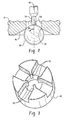
- FIG. 2 is an enlarged view of a portion of FIG. 1 showing the check ball seat
- FIG. 3 is a perspective view of the check ball retainer valve of FIG. 1;
- FIG. 4a is the left hand portion of a perspective view of the valve of FIG. 1 divided along dividing lines IV-IV;
- FIG. 4b is the right-hand portion of a perspective view of the valve of FIG. 1 divided along dividing lines IV-IV;
- FIG. 5 graphically presents exhaust port flow plotted as a function of coil current for the valve assembly of the present invention and for the prior art.
- the valve assembly of the present invention is indicated generally at 10 and includes a solenoid operator indicated generally at 12 having a coil 14 and an armature 16 moveably disposed therewithin with the solenoid operator 12 being mounted on a valve body subassembly indicated generally at 18.
- the solenoid operator may be secured to the valve body by an outer casing or cover received over a flange 22 provided on the upper end of the valve body 19 with the casing having an inwardly extending flange denoted by reference numeral 24 registered against the undersurface of body flange 22.
- the upper end of the casing (not shown in FIG. 1) is then retained over the operator 12 as for example by crimping or staking.
- Valve body 19 has a valving chamber denoted by reference numeral 26 which has at least one and preferably a plurality of exhaust or sump return ports 28 formed therein spaced from at least one and preferably a plurality of control pressure signal outlet ports 30.
- An inlet pressure valve seat 32 is spaced from the control pressure ports 30.
- the inlet pressure valve seat communicates with a high pressure inlet passage 34 which may be formed in a retaining ring 36 threadedly engaged in the lower end of the valve body 18.
- An inlet valve member in the form of a check ball 38 is disposed against the valve seat 32 and retained thereon by a fluted or grooved retaining ring 40 which is illustrated in perspective in FIG. 3.
- Ring 40 may have a plurality of radially inwardly extending projections 42 from the material intermittent a plurality of circumferentially spaced radially extending grooves to form a support for the check ball 38.
- the retainer 40 is biased against the check ball by a spring 44 with a calibrated preload provided by rotatably adjusting the threaded ring 36.
- the valve seat 32 is preferably formed as a sharp edge by the conical surface 46 formed in the valve body with the intersection of the conical surface 46 and a passage 50 through valve seat for communicating inlet 34 with the valving chamber 26.
- the diameter of the valve seat 32 is chosen to make an angle ⁇ as shown in FIG. 2 of about 60 degrees with the center line 48 of the armature. This arrangement of a relatively sharp edge between the conically tapered surface 46 and the passage 50 through the valve provides reliable seating of the ball 38 on the seat 32 and thus ensures complete shutoff of the flow from the inlet to the control pressure signal outlet port 30.
- the armature 16 has an operating rod 52 connected thereto, preferably by press fitting through the annular armature 16, for movement therewith.
- Rod 52 has a reduced diameter portion 54 provided on the lower end thereof which extends through the valving passage 26 and through valve seat passage 50 with the end thereof making contact with ball 38.
- the operating rod has provided thereon an annular valving surface 56 on the shoulder formed by the transition to the smaller diameter 54; and, the valving surface 56 is positioned for movement with respect to an annular valve seat 58 formed in the valving chamber 26 between the pressure control signal outlet port 30 and the exhaust port 28.
- Valve body 19 has a seal preferably in the form of a flexible diaphragm 60 provided therein which provides a moveable seal about the operating rod 52 for sealing the upper end of the valving chamber 26.
- the diaphragm may be preassembled onto a washer 62 and the washer press fitted into a counterbore 64 formed in the body.
- Coil 14 is wound on a bobbin 66 and is supported by an annular lower flux collector 68.
- An outer sleeve 70 is received over the coil for spacing the lower flux collector 68 and an upper flux collector 72 (see FIG. 4a).
- the body is put together as a subassembly indicated by reference numeral 18 in FIG. 4b; and, the solenoid actuator is put together as a subassembly indicated by reference numeral 12 in FIG. 4a.
- the two subassemblies 12, 18 are then assembled together and the outer casing 20 is assembled thereover with the upper end thereof retained thereover by any suitable expedient, such as by crimping or staking, to retain the complete assembly 10.
- O-ring seals 74, 76 may be provided in annular grooves 78, 80 formed on axially opposite sides of the control pressure signal ports 30.
- the spring 44 biases the ball retainer 40 against the under side of check ball 38 maintaining the check ball against valve seat 32 with the coil in the de-energized state.
- armature 16 moves operating rod 52 to cause the lower end thereof to press against ball 38 to overcome the force of spring 44 at a desired current level and move ball 38 away from seat 32, whereupon flow is permitted through passage 34 and through passage 50 to the valving chamber 26 providing a pressure control signal through outlet ports 30.
- the pressure in the valving chamber and outlet ports 30 is controlled by the valving surface 56 moving with respect to the valve seat 58 to control bleed flow through the exhaust ports 28. It will be understood that the movement of the valving surface 56 is controlled by applying a desired current to the coil 14. If full current is applied through coil 14, the valving surface 56 closes against valve seat 50 preventing flow to the exhaust ports 28 and thereby applying full inlet pressure to the pressure signal control ports 30.
- the present invention thus provides a solenoid operated valve for providing a fluid pressure control signal proportional to the electric current applied to the solenoid in which a ball check valve provides complete inlet shutoff when the valve is de-energized to prevent unwanted bleed flow in the system and eliminating the pump energy which results from such bleed flow.
- the flow from the supply inlet port to the exhaust port with the control signal port blocked in cubic centimeters per second (CC/S) is plotted as a function of coil current in amperes separately for both the valve assembly of the present invention and a prior art valve without the inlet shutoff ball valve. It will be seen from the graphs of FIG. 5 that unlike a valve without the ball shutoff, the valve assembly of the present invention does not permit flow until a desired amount of coil energization of about 0.3 amperes is provided.
Landscapes
- Engineering & Computer Science (AREA)
- General Engineering & Computer Science (AREA)
- Physics & Mathematics (AREA)
- Fluid Mechanics (AREA)
- Mechanical Engineering (AREA)
- General Physics & Mathematics (AREA)
- Automation & Control Theory (AREA)
- Magnetically Actuated Valves (AREA)
Applications Claiming Priority (2)
| Application Number | Priority Date | Filing Date | Title |
|---|---|---|---|
| US51524 | 2002-01-18 | ||
| US10/051,524 US20030136449A1 (en) | 2002-01-18 | 2002-01-18 | Solenoid operated variable bleed pressure control valve with integral shutoff feature |
Publications (2)
| Publication Number | Publication Date |
|---|---|
| EP1329785A2 true EP1329785A2 (de) | 2003-07-23 |
| EP1329785A3 EP1329785A3 (de) | 2004-12-08 |
Family
ID=21971837
Family Applications (1)
| Application Number | Title | Priority Date | Filing Date |
|---|---|---|---|
| EP03000794A Withdrawn EP1329785A3 (de) | 2002-01-18 | 2003-01-14 | Elektromagnetisch betätigtes Druckregelungsventil mit variablem Durchlass, das ein integriertes Absperrorgan aufweist |
Country Status (7)
| Country | Link |
|---|---|
| US (1) | US20030136449A1 (de) |
| EP (1) | EP1329785A3 (de) |
| JP (1) | JP2003214553A (de) |
| KR (1) | KR20030063187A (de) |
| AU (1) | AU2003200125A1 (de) |
| CA (1) | CA2416774A1 (de) |
| MX (1) | MXPA03000583A (de) |
Cited By (2)
| Publication number | Priority date | Publication date | Assignee | Title |
|---|---|---|---|---|
| EP1911999A1 (de) * | 2006-10-10 | 2008-04-16 | Robert Bosch Gmbh | Ventilkörper und zugehöriges Magnetventil |
| US7823602B2 (en) | 2004-12-18 | 2010-11-02 | Luk Lamellen Und Kupplungsbau Beteiligungs Kg | Hydraulic system having at least one hydraulic valve for actuating a component |
Families Citing this family (12)
| Publication number | Priority date | Publication date | Assignee | Title |
|---|---|---|---|---|
| DE10359364B4 (de) * | 2003-12-18 | 2012-10-11 | Schaeffler Technologies Gmbh & Co. Kg | Elektromagnetisches Hydraulikventil, insbesondere 3/2-Wegeschaltventil zur Steuerung eines varialblen Ventiltriebes einer Brennkraftmaschine |
| US7331564B2 (en) * | 2005-04-22 | 2008-02-19 | Delphi Technologies, Inc. | Normally open high flow hydraulic pressure control actuator |
| US7766040B2 (en) * | 2007-03-13 | 2010-08-03 | Eaton Corporation | Pressure control valve assembly |
| JP4301318B2 (ja) * | 2007-04-19 | 2009-07-22 | 株式会社デンソー | ブリード式バルブ装置 |
| KR100836403B1 (ko) | 2007-07-06 | 2008-06-09 | 현대자동차주식회사 | 차량의 브레이크 마스터실린더 차단밸브 및 그를 이용한차간거리 제어 해제방법 |
| DE102008000106A1 (de) * | 2008-01-21 | 2009-07-23 | Zf Friedrichshafen Ag | Druckregelventilvorrichtung |
| DE102011079366A1 (de) | 2011-07-19 | 2013-01-24 | Zf Friedrichshafen Ag | Druckregelventilvorrichtung mit einer Strömungsführungseinrichtung |
| DE102011087264B4 (de) * | 2011-11-29 | 2023-01-19 | Zf Friedrichshafen Ag | Druckregelventilvorrichtung |
| CN102889405A (zh) * | 2012-10-12 | 2013-01-23 | 机科发展科技股份有限公司 | 一种高速定量排油阀 |
| US10364136B2 (en) * | 2016-09-26 | 2019-07-30 | Gate Cfv Solutions, Inc. | Valve device |
| KR102579702B1 (ko) * | 2021-11-26 | 2023-09-18 | 하이드로텍(주) | 유압제어용 솔레노이드 체크밸브 |
| CN120938529B (zh) * | 2025-09-08 | 2026-04-07 | 北京华信医院(清华大学第一附属医院) | 止血带 |
Family Cites Families (20)
| Publication number | Priority date | Publication date | Assignee | Title |
|---|---|---|---|---|
| US4338966A (en) * | 1979-02-09 | 1982-07-13 | Chrysler Corporation | Direct solenoid operated directional control valve |
| US4998559A (en) * | 1988-09-13 | 1991-03-12 | Coltec Industries Inc. | Solenoid operated pressure control valve |
| DE3938136A1 (de) * | 1989-11-16 | 1991-05-23 | Bosch Gmbh Robert | Elektromagnetisch betaetigbares ventil |
| US5104091A (en) * | 1991-05-14 | 1992-04-14 | United Technologies Corporation | Spring assisted ball valve |
| JP3131015B2 (ja) * | 1992-04-03 | 2001-01-31 | 株式会社鷺宮製作所 | 電磁式制御弁 |
| DE4337763A1 (de) * | 1993-11-05 | 1995-05-11 | Teves Gmbh Alfred | Druckregelventil |
| US5606992A (en) * | 1994-05-18 | 1997-03-04 | Coltec Industries Inc. | Pulse width modulated solenoid |
| EP0689015A1 (de) * | 1994-06-21 | 1995-12-27 | Staefa Control System Scs Ag | Regelventil mit Stellantrieb |
| US5651391A (en) * | 1996-05-06 | 1997-07-29 | Borg-Warner Automotive, Inc. | Three-way solenoid valve |
| US5711344A (en) * | 1996-08-23 | 1998-01-27 | Saturn Electronics & Engineering, Inc. | Electromechanical fluid control valve with spiral centering member for valve actuating pin |
| DE19744696A1 (de) * | 1997-10-10 | 1999-04-15 | Zahnradfabrik Friedrichshafen | Druckregelventil |
| US6418967B1 (en) * | 1997-04-18 | 2002-07-16 | Zf Friedrichshafen Ag | Pressure regulating valve |
| JP3471568B2 (ja) * | 1997-06-18 | 2003-12-02 | 三菱電機株式会社 | 三方電磁弁 |
| DE19733660A1 (de) * | 1997-08-04 | 1999-02-25 | Bosch Gmbh Robert | Elektromagnetisches Druckregelventil |
| DE19810241C2 (de) * | 1998-03-10 | 2001-07-05 | Bosch Gmbh Robert | Elektromagnetisches Wegeventil |
| US6116269A (en) * | 1998-07-07 | 2000-09-12 | Fasco Controls Corporation | Solenoid pressure transducer |
| DE50012876D1 (de) * | 1999-02-22 | 2006-07-20 | Hydraulik Ring Gmbh | Wegesitzventil |
| DE19927047A1 (de) * | 1999-06-14 | 2000-12-21 | Kendrion Binder Magnete Gmbh | Magnetregelventil |
| JP2001173816A (ja) * | 1999-12-17 | 2001-06-29 | Denso Corp | 逆止弁及びそれを用いた燃料噴射ポンプ |
| DE10034959A1 (de) * | 2000-07-19 | 2002-02-21 | Zahnradfabrik Friedrichshafen | Proportional-Druckregelventil |
-
2002
- 2002-01-18 US US10/051,524 patent/US20030136449A1/en not_active Abandoned
-
2003
- 2003-01-13 AU AU2003200125A patent/AU2003200125A1/en not_active Abandoned
- 2003-01-14 EP EP03000794A patent/EP1329785A3/de not_active Withdrawn
- 2003-01-17 KR KR10-2003-0003306A patent/KR20030063187A/ko not_active Withdrawn
- 2003-01-17 CA CA002416774A patent/CA2416774A1/en not_active Abandoned
- 2003-01-20 MX MXPA03000583A patent/MXPA03000583A/es unknown
- 2003-01-20 JP JP2003011076A patent/JP2003214553A/ja active Pending
Non-Patent Citations (1)
| Title |
|---|
| None |
Cited By (2)
| Publication number | Priority date | Publication date | Assignee | Title |
|---|---|---|---|---|
| US7823602B2 (en) | 2004-12-18 | 2010-11-02 | Luk Lamellen Und Kupplungsbau Beteiligungs Kg | Hydraulic system having at least one hydraulic valve for actuating a component |
| EP1911999A1 (de) * | 2006-10-10 | 2008-04-16 | Robert Bosch Gmbh | Ventilkörper und zugehöriges Magnetventil |
Also Published As
| Publication number | Publication date |
|---|---|
| EP1329785A3 (de) | 2004-12-08 |
| CA2416774A1 (en) | 2003-07-18 |
| KR20030063187A (ko) | 2003-07-28 |
| MXPA03000583A (es) | 2003-07-29 |
| US20030136449A1 (en) | 2003-07-24 |
| JP2003214553A (ja) | 2003-07-30 |
| AU2003200125A1 (en) | 2003-08-07 |
Similar Documents
| Publication | Publication Date | Title |
|---|---|---|
| EP1329785A2 (de) | Elektromagnetisch betätigtes Druckregelungsventil mit variablem Durchlass, das ein integriertes Absperrorgan aufweist | |
| US4121619A (en) | Tapered valves with conical seats | |
| US9669533B2 (en) | Multi-operational valve | |
| EP2449290B1 (de) | Hydraulikventil zur verwendung in einem steuermodul eines automatikgetriebes | |
| US6899313B2 (en) | Magnetic actuator and method | |
| US6866063B2 (en) | Low leak pressure control actuator | |
| JPH10509928A (ja) | 圧力制御弁 | |
| US6810909B2 (en) | Solenoid operated pressure control valve | |
| AU4384001A (en) | Solenoid operated pressure control valve | |
| JPH02286976A (ja) | 圧力作動式逆止弁 | |
| US4298027A (en) | Three-way normally closed pilot valve | |
| EP3129660B1 (de) | Servoventil | |
| EP0341513B1 (de) | Direktwirkendes magnetbetätigtes Ventil mit nicht engem Luftspalt | |
| WO2010088168A1 (en) | Solenoid actuated hydraulic valve for use in an automatic transmission | |
| EP1143178B1 (de) | Servolenkung mit variabler Unterstützung und Durchflussregelventil dafür | |
| EP1186815A2 (de) | Solenoidventil mit Proportionalkontrol des Druckablasses | |
| KR20070118960A (ko) | 압력 조절 밸브 | |
| CN114402154A (zh) | 具有增加的流速的低功率液压阀 | |
| US4949752A (en) | Thermally compensated noise control device for a solenoid-actuated valve | |
| JP2017115990A (ja) | バルブ装置 | |
| US9476514B2 (en) | Valve, in particular a pressure regulating valve or pressure limiting valve | |
| JP2008506910A (ja) | 電気的に制御可能な弁 | |
| GB2103337A (en) | Three-way normally closed pilot valve | |
| EP0310733B1 (de) | Hydropneumatischer Betätiger für Kraftfahrzeuge | |
| US20020117216A1 (en) | Solenoid operated valve with hydraulic dampening |
Legal Events
| Date | Code | Title | Description |
|---|---|---|---|
| PUAI | Public reference made under article 153(3) epc to a published international application that has entered the european phase |
Free format text: ORIGINAL CODE: 0009012 |
|
| AK | Designated contracting states |
Designated state(s): AT BE BG CH CY CZ DE DK EE ES FI FR GB GR HU IE IT LI LU MC NL PT SE SI SK TR |
|
| AX | Request for extension of the european patent |
Extension state: AL LT LV MK RO |
|
| PUAL | Search report despatched |
Free format text: ORIGINAL CODE: 0009013 |
|
| AK | Designated contracting states |
Kind code of ref document: A3 Designated state(s): AT BE BG CH CY CZ DE DK EE ES FI FR GB GR HU IE IT LI LU MC NL PT SE SI SK TR |
|
| AX | Request for extension of the european patent |
Extension state: AL LT LV MK RO |
|
| AKX | Designation fees paid | ||
| REG | Reference to a national code |
Ref country code: DE Ref legal event code: 8566 |
|
| STAA | Information on the status of an ep patent application or granted ep patent |
Free format text: STATUS: THE APPLICATION IS DEEMED TO BE WITHDRAWN |
|
| 18D | Application deemed to be withdrawn |
Effective date: 20050801 |