EP1329888B1 - Mehrschichtiges Informationsaufzeichnungsmedium, Wiedergabegerät, Aufzeichnungsgerät, Wiedergabeverfahren und Aufzeichnungsverfahren - Google Patents
Mehrschichtiges Informationsaufzeichnungsmedium, Wiedergabegerät, Aufzeichnungsgerät, Wiedergabeverfahren und Aufzeichnungsverfahren Download PDFInfo
- Publication number
- EP1329888B1 EP1329888B1 EP03000696.9A EP03000696A EP1329888B1 EP 1329888 B1 EP1329888 B1 EP 1329888B1 EP 03000696 A EP03000696 A EP 03000696A EP 1329888 B1 EP1329888 B1 EP 1329888B1
- Authority
- EP
- European Patent Office
- Prior art keywords
- area
- defect list
- storing area
- storing
- recording medium
- Prior art date
- Legal status (The legal status is an assumption and is not a legal conclusion. Google has not performed a legal analysis and makes no representation as to the accuracy of the status listed.)
- Expired - Lifetime
Links
- 238000000034 method Methods 0.000 title claims description 88
- 230000007547 defect Effects 0.000 claims description 481
- 230000002950 deficient Effects 0.000 claims description 171
- 230000003287 optical effect Effects 0.000 claims description 91
- 239000010410 layer Substances 0.000 description 401
- 238000007726 management method Methods 0.000 description 205
- 230000008569 process Effects 0.000 description 52
- 238000010586 diagram Methods 0.000 description 34
- 230000015556 catabolic process Effects 0.000 description 7
- 238000006731 degradation reaction Methods 0.000 description 7
- 238000001514 detection method Methods 0.000 description 5
- 230000000694 effects Effects 0.000 description 5
- 238000004519 manufacturing process Methods 0.000 description 5
- 238000006243 chemical reaction Methods 0.000 description 3
- 230000006870 function Effects 0.000 description 3
- 230000000717 retained effect Effects 0.000 description 3
- 239000000758 substrate Substances 0.000 description 3
- 238000012937 correction Methods 0.000 description 2
- 230000001965 increasing effect Effects 0.000 description 2
- 239000000463 material Substances 0.000 description 2
- 230000009467 reduction Effects 0.000 description 2
- 238000013459 approach Methods 0.000 description 1
- 230000001174 ascending effect Effects 0.000 description 1
- 230000015572 biosynthetic process Effects 0.000 description 1
- 230000000295 complement effect Effects 0.000 description 1
- 230000006866 deterioration Effects 0.000 description 1
- 230000002708 enhancing effect Effects 0.000 description 1
- 230000006872 improvement Effects 0.000 description 1
- 238000012986 modification Methods 0.000 description 1
- 230000004048 modification Effects 0.000 description 1
- 230000002093 peripheral effect Effects 0.000 description 1
- 239000011347 resin Substances 0.000 description 1
- 229920005989 resin Polymers 0.000 description 1
- 230000004044 response Effects 0.000 description 1
- 230000000630 rising effect Effects 0.000 description 1
- 238000004904 shortening Methods 0.000 description 1
- 239000002356 single layer Substances 0.000 description 1
- 238000000547 structure data Methods 0.000 description 1
- 238000012360 testing method Methods 0.000 description 1
- 238000012795 verification Methods 0.000 description 1
Images


Classifications
-
- G—PHYSICS
- G11—INFORMATION STORAGE
- G11B—INFORMATION STORAGE BASED ON RELATIVE MOVEMENT BETWEEN RECORD CARRIER AND TRANSDUCER
- G11B20/00—Signal processing not specific to the method of recording or reproducing; Circuits therefor
- G11B20/10—Digital recording or reproducing
- G11B20/18—Error detection or correction; Testing, e.g. of drop-outs
- G11B20/1883—Methods for assignment of alternate areas for defective areas
-
- G—PHYSICS
- G11—INFORMATION STORAGE
- G11B—INFORMATION STORAGE BASED ON RELATIVE MOVEMENT BETWEEN RECORD CARRIER AND TRANSDUCER
- G11B7/00—Recording or reproducing by optical means, e.g. recording using a thermal beam of optical radiation by modifying optical properties or the physical structure, reproducing using an optical beam at lower power by sensing optical properties; Record carriers therefor
- G11B7/007—Arrangement of the information on the record carrier, e.g. form of tracks, actual track shape, e.g. wobbled, or cross-section, e.g. v-shaped; Sequential information structures, e.g. sectoring or header formats within a track
-
- G—PHYSICS
- G11—INFORMATION STORAGE
- G11B—INFORMATION STORAGE BASED ON RELATIVE MOVEMENT BETWEEN RECORD CARRIER AND TRANSDUCER
- G11B20/00—Signal processing not specific to the method of recording or reproducing; Circuits therefor
- G11B20/10—Digital recording or reproducing
- G11B20/12—Formatting, e.g. arrangement of data block or words on the record carriers
-
- G—PHYSICS
- G11—INFORMATION STORAGE
- G11B—INFORMATION STORAGE BASED ON RELATIVE MOVEMENT BETWEEN RECORD CARRIER AND TRANSDUCER
- G11B27/00—Editing; Indexing; Addressing; Timing or synchronising; Monitoring; Measuring tape travel
- G11B27/10—Indexing; Addressing; Timing or synchronising; Measuring tape travel
- G11B27/19—Indexing; Addressing; Timing or synchronising; Measuring tape travel by using information detectable on the record carrier
- G11B27/28—Indexing; Addressing; Timing or synchronising; Measuring tape travel by using information detectable on the record carrier by using information signals recorded by the same method as the main recording
- G11B27/32—Indexing; Addressing; Timing or synchronising; Measuring tape travel by using information detectable on the record carrier by using information signals recorded by the same method as the main recording on separate auxiliary tracks of the same or an auxiliary record carrier
- G11B27/327—Table of contents
- G11B27/329—Table of contents on a disc [VTOC]
-
- G—PHYSICS
- G11—INFORMATION STORAGE
- G11B—INFORMATION STORAGE BASED ON RELATIVE MOVEMENT BETWEEN RECORD CARRIER AND TRANSDUCER
- G11B7/00—Recording or reproducing by optical means, e.g. recording using a thermal beam of optical radiation by modifying optical properties or the physical structure, reproducing using an optical beam at lower power by sensing optical properties; Record carriers therefor
- G11B7/004—Recording, reproducing or erasing methods; Read, write or erase circuits therefor
-
- G—PHYSICS
- G11—INFORMATION STORAGE
- G11B—INFORMATION STORAGE BASED ON RELATIVE MOVEMENT BETWEEN RECORD CARRIER AND TRANSDUCER
- G11B7/00—Recording or reproducing by optical means, e.g. recording using a thermal beam of optical radiation by modifying optical properties or the physical structure, reproducing using an optical beam at lower power by sensing optical properties; Record carriers therefor
- G11B7/24—Record carriers characterised by shape, structure or physical properties, or by the selection of the material
- G11B7/2403—Layers; Shape, structure or physical properties thereof
- G11B7/24035—Recording layers
- G11B7/24038—Multiple laminated recording layers
-
- G—PHYSICS
- G11—INFORMATION STORAGE
- G11B—INFORMATION STORAGE BASED ON RELATIVE MOVEMENT BETWEEN RECORD CARRIER AND TRANSDUCER
- G11B20/00—Signal processing not specific to the method of recording or reproducing; Circuits therefor
- G11B20/10—Digital recording or reproducing
- G11B20/18—Error detection or correction; Testing, e.g. of drop-outs
- G11B20/1816—Testing
- G11B2020/1826—Testing wherein a defect list or error map is generated
-
- G—PHYSICS
- G11—INFORMATION STORAGE
- G11B—INFORMATION STORAGE BASED ON RELATIVE MOVEMENT BETWEEN RECORD CARRIER AND TRANSDUCER
- G11B20/00—Signal processing not specific to the method of recording or reproducing; Circuits therefor
- G11B20/10—Digital recording or reproducing
- G11B20/18—Error detection or correction; Testing, e.g. of drop-outs
- G11B20/1883—Methods for assignment of alternate areas for defective areas
- G11B2020/1893—Methods for assignment of alternate areas for defective areas using linear replacement to relocate data from a defective block to a non-contiguous spare area, e.g. with a secondary defect list [SDL]
-
- G—PHYSICS
- G11—INFORMATION STORAGE
- G11B—INFORMATION STORAGE BASED ON RELATIVE MOVEMENT BETWEEN RECORD CARRIER AND TRANSDUCER
- G11B2220/00—Record carriers by type
- G11B2220/20—Disc-shaped record carriers
-
- G—PHYSICS
- G11—INFORMATION STORAGE
- G11B—INFORMATION STORAGE BASED ON RELATIVE MOVEMENT BETWEEN RECORD CARRIER AND TRANSDUCER
- G11B2220/00—Record carriers by type
- G11B2220/20—Disc-shaped record carriers
- G11B2220/21—Disc-shaped record carriers characterised in that the disc is of read-only, rewritable, or recordable type
- G11B2220/215—Recordable discs
- G11B2220/216—Rewritable discs
-
- G—PHYSICS
- G11—INFORMATION STORAGE
- G11B—INFORMATION STORAGE BASED ON RELATIVE MOVEMENT BETWEEN RECORD CARRIER AND TRANSDUCER
- G11B2220/00—Record carriers by type
- G11B2220/20—Disc-shaped record carriers
- G11B2220/23—Disc-shaped record carriers characterised in that the disc has a specific layer structure
- G11B2220/235—Multilayer discs, i.e. multiple recording layers accessed from the same side
- G11B2220/237—Multilayer discs, i.e. multiple recording layers accessed from the same side having exactly two recording layers
-
- G—PHYSICS
- G11—INFORMATION STORAGE
- G11B—INFORMATION STORAGE BASED ON RELATIVE MOVEMENT BETWEEN RECORD CARRIER AND TRANSDUCER
- G11B2220/00—Record carriers by type
- G11B2220/20—Disc-shaped record carriers
- G11B2220/25—Disc-shaped record carriers characterised in that the disc is based on a specific recording technology
- G11B2220/2537—Optical discs
- G11B2220/2562—DVDs [digital versatile discs]; Digital video discs; MMCDs; HDCDs
- G11B2220/2575—DVD-RAMs
Definitions
- the present invention relates to a multi-layered information recording medium comprising at least two recording layers, a reproduction apparatus, a recording apparatus for use with the multi-layered information recording medium, a reproduction method for reproducing information from the multi-layered information recording medium, and a recording method for recording information in the multi-layered information recording medium.
- a typical information recording medium which has a sector structure is an optical disc.
- AV data such as audio data, video data, and the like
- an optical disc having a higher recording density and a larger capacity has been demanded.
- Providing a plurality of recording layers is useful in increasing the capacity of a disc. For example, the capacity of a read-only DVD has been increased about two times by providing two recording layers to the DVD.
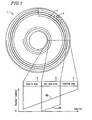
- Figure 1 shows a structure of a typical optical disc medium 1 including a track 2 and sectors 3.
- the track 2 is turned multiple times in a spiral arrangement.
- the track 2 is divided into a large number of small sectors 3 .
- Regions formed on the disc medium 1 are roughly classified into a lead-in area 4 , a user data area 8 , and a lead-out area 6 . Recording or reproduction of user data is performed on the user data area 8 .
- the lead-in area 4 and the lead-out area 6 are provided as margins such that an optical head (not shown) can appropriately follow a track even if overrunning of the optical head occurs when the optical head approaches an end portion of the user data area 8.
- the lead-in area 4 includes a disc information area which stores parameters necessary for accessing the disc medium 1 .
- Physical sector numbers (hereinafter, abbreviated as "PSN(s)”) are assigned to the sectors 3 in order to identify the respective sectors 3 .
- consecutive logical sector numbers (hereinafter, abbreviated as "LSN(s)”) which start with 0 are assigned to the sectors 3 included in the user data area 8 such that a high level apparatus (not shown) such as a host computer identifies the respective sectors 3 .
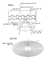
- Figure 2 illustrates a principle of reproduction of data from a read-only optical disc 30 having two recording layers.
- production of the read-only optical disc 30 of Figure 2 is briefly described.
- Grooves are formed on transparent substrates 31 and 32 so as to form spiral tracks .
- recording layers 33 and 34 are attached so as to cover the grooved surfaces, respectively.
- the substrates 31 and 32 are attached together so as to sandwich a transparent light-curable resin 35 between the recording layers 33 and 34, thereby obtaining a single read-only optical disc 30.
- a recording layer 34 closer to the incoming laser light 38 is referred to as a first recording layer 34; whereas the other recording layer 33 is referred to as a second recording layer 33.
- the thickness and composition of the first recording layer 34 are adjusted such that the first recording layer 34 reflects a half of the incoming laser light 38 and transmits the other half of the incoming laser light 38.
- the thickness and composition of the second recording layer 33 are adjusted such that the second recording layer 33 reflects all of the incoming laser light 38.
- An objective lens 37 for converging the laser light 38 is moved toward or away from the read-only optical disc 30 such that the convergence point (beam spot) 36 of the laser light 38 is placed on the first recording layer 34 or the second recording layer 33.
- Figures 3A , 3B, 3C and 3D show tracks of two recording layers 41 and 42 of a read-only DVD, which are called parallel paths, and the reproduction direction and sector numbers.
- Figure 3A shows a spiral groove pattern of the second recording layer 42.
- Figure 3B shows a spiral groove pattern of the first recording layer 41.
- Figure 3C shows the reproduction direction in user data areas 8 provided on the recording layers 41 and 42.
- Figure 3D shows sector numbers assigned to the recording layers 41 and 42.
- the read-only DVD disc is rotated clockwise when it is viewed from the back face side of the disc in the direction along which laser light comes onto the disc, i.e., when it is viewed from the back side of the sheets of Figures 3A and 3B .
- the laser light moves along the track 2 from the inner periphery to the outer periphery of the recording layers 41 and 42.
- reproduction is first performed from the innermost periphery to the outermost periphery of the user data area 8 of the first recording layer 41 .
- reproduction is performed from the innermost periphery to the outermost periphery of the user data area 8 of the second recording layer 42 .
- the user data areas 8 of the first and second recording layers 41 and 42 are sandwiched by the lead-in area 4 and the lead-out area 6 such that an optical head can appropriately follow the track 2 even if overrunning of the optical head occurs.
- the PSNs and LSNs of each of the recording layers 41 and 42 are incrementally assigned along the reproduction direction. The PSNs do not necessarily need to start with 0 in view of convenience of disc formation.
- the PSNs do not necessarily need to be continuously assigned between the first and second recording layers 41 and 42 (for example, a value corresponding to the layer number may be provided at the first location of each sector number).
- LSNs consecutive numbers which start with 0 are assigned to all of the user data areas 8 included in the optical disc. That is, in the user data area 8 of the first recording layer 41, the LSN at the innermost periphery is 0, and increases by ones toward the outermost perimeter.
- the LSN at the innermost periphery of the user data area 8 of the second recording layer 42 is a number obtained by adding 1 to the maximum LSN of the first recording layer 41 .
- the LSN of the second recording layer 42 also increments by ones toward the outermost perimeter.
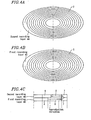
- Figures 4A, 4B, 4C and 4D show tracks of two recording layers 43 and 44 of a read-only DVD, which is called an opposite path arrangement, and the reproduction direction and sector numbers.
- Figure 4A shows a spiral groove pattern of the second recording layer 44.
- Figure 4B shows a spiral groove pattern of the first recording layer 43.
- Figure 4C shows the reproduction direction in user data areas 8 provided on the recording layers 43 and 44.
- Figure 4D shows sector numbers assigned to the recording layers 43 and 44.
- the read-only DVD disc is rotated clockwise when it is viewed from the back face side of the disc in the direction along which laser light comes onto the disc, i.e., when it is viewed from the back side of the sheets of Figures 4A and 4B .
- the laser light moves along the track 2 from the inner periphery to the outer periphery in the first recording layer 43 , but from the outer periphery to the inner periphery in the second recording layer 44.
- reproduction is first performed from the innermost periphery to the outermost periphery of the user data area 8 of the first recording layer 43 , and then, reproduction is performed from the outermost periphery to the innermost periphery of the user data area 8 of the second recording layer 44.
- the user data area 8 of the first recording layer 43 is sandwiched by the lead-in area 4 and a middle area 7 such that an optical head can appropriately follow the track 2 even if overrunning of the optical head occurs.
- the user data area 8 of the second recording layer 44 is sandwiched by the middle area 7 and the lead-out area 6 .
- the function of the middle area 7 is the same as that of the lead-out area 6 .
- the PSNs and LSNs of each of the recording layers 43 and 44 are incrementally assigned along the reproduction direction as in the above-described parallel paths, except that the relationship between the sector numbers and the radial direction is changed because the spiral direction of the track 2 of the second recording layer 44 is inverse to the spiral direction of the track 2 of the first recording layer 43.
- the LSN is 0 at the innermost periphery, and increments by ones toward the outer periphery.
- the LSN at the outermost periphery in the user data area 8 of the second recording layer 44 is a number obtained by adding 1 to the maximum LSN in the user data area 8 of the first recording layer 43, and increments by ones toward the innermost perimeter.
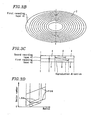
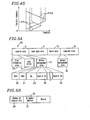
- Figure 5A shows an area layout of a typical rewritable disc 45.
- the rewritable disc 45 includes only one recording layer.
- a lead-in area 4 of the rewritable disc 45 includes a disc information area 10 and an OPC (Optimum Power Calibration) area 11 , and a defect management area 12 .
- the lead-out area 6 includes another defect management area 12.
- a user data area 8 and a spare area 13 are provided between a lead-in area 4 and a lead-out area 6 .
- a disc information area 10 stores disc information regarding a parameter(s) or a format necessary for recording/reproduction of data of the optical disc.
- the disc information area 10 is also included in a read-only optical disc, but the disc information area 10 of the read-only optical disc includes nothing important other than a format identifier used for identifying the optical disc.
- specific recommended values for the characteristics of the laser light used for recording such as laser power, pulse width, and the like, are stored for each generated mark width.
- the disc information area 10 is a read-only area in which information is typically written at the time of production of the disc.
- pits are formed in the disc surface as in a DVD-ROM or a CD-ROM.
- a recording principle different from such a "pit” recording principle For example, in a CD-RW, information is embedded in a meandering pattern (called "wobble") of a groove.)
- the OPC area 11 is provided for optimally adjusting the recording power of laser light.
- a disc manufacturer stores recommended laser parameters for a recording operation in the disc information area 10.
- a laser element used by the disc manufacturer for obtaining the recommended values is different from a laser element incorporated in an optical disc drive apparatus, in respect to laser characteristics, such as the wavelength, the rising time of the laser power, and the like.
- the laser characteristics thereof vary because of a variation of the ambient temperature or deterioration which occurs over time.
- test recording is performed on the OPC area 11 while increasingly and decreasingly changing the laser parameters stored in the disc information area 10 so as to obtain an optimum recording power.
- a defect management area 12 and a spare areas 13 are provided for defect management, i.e., provided for replacing a sector of the user data area 8 in which recording/reproduction cannot be appropriately performed (referred to as a "defective sector") with another well-conditioned (i.e., sufficiently usable) sector.
- defect management is generally performed in a rewritable single-layer optical disc, such as a 650 MB phase-change optical disc (called a PD) defined in the ECMA-240 format, or the like.
- the spare area 13 includes a sector for replacing a defective sector (referred to as a spare sector).
- a sector which is already employed in place of a defective sector is referred to as a replacement sector.
- spare areas 13 are placed at two positions, one at the inner periphery and the other at the outer periphery of the user data area 8 .
- spare areas 13 are provided at 10 positions, and their arrangement varies depending on the medium.
- a spare area 13 is provided at only one portion at the outer periphery of the user data area 8 .
- the defect management area 12 includes: a disc definition structure (DDS) storing area 20 storing a format designed for defect management, which includes the size of the spare area 13 and the position where the spare area 13 is placed; a defect management sector (DMS) storing area 21 storing data for managing the defect of the defect management area 12 itself; a defect list (DL) storing area 22 storing a list of defects containing the positions of defective sectors and the positions of replacement sectors; and a spare defective list (spare DL) storing area 23 which is used to replace the defect list (DL) storing area 22 when it is not usable.
- DDS disc definition structure
- DMS defect management sector
- DL defect list
- spare defective list spare defective list
- each of the inner perimeter portion and outer perimeter portion of a disc has one defect management area 12, and each defect management area 12 duplicately stores the same contents, i.e., the defect management areas 12 of the disc have the four copies of the same contents in total.
- Figure 5B shows data stored in a DMS 21.
- the data stored in the DMS 21 are the number of DL sectors 30 which indicates the number of sectors storing a defect list, and a list of DL sector addresses 31 each of which indicates the address of a sector.
- DL storing areas 22 each are herein assumed to include only one sector. If it is determined that a DL storing area 22 is defective when updating a defect list because of detection of a new defective sector, the following spare DL storing area 23 is used to record the defect list. In this case, the DL sector address list 31 is updated so as to indicate the sector address of the spare DL storing 23 .
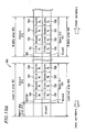
- Figure 5C shows data stored in a DL storing area 22.
- the data stored in the DL storing area 22 are a DL identifier 32 which is a unique identifier for identifying a defect list, and the number of defective sectors 33 registered on the defect list.
- the DL storing area 22 further includes a plurality of defect entry areas 34 each including the address of a defective sector and the address of a replacement sector. It is now assumed that there are n defects registered (n is an integer greater than or equal to 3). In this case, the number of defective sectors 33 indicates n.
- a first defect entry area 34 stores a replacement status 40 , a defective sector address 41 , and a replacement sector address 42.
- a single defect entry area stores information relating to a process for replacing a single defective sector.
- the replacement status 40 is a flag indicating whether or not replacement is applied to a defective sector.
- a value 0 is set in the replacement status 40 .
- a value 1 is set in the replacement status 40.
- an optical disc drive apparatus accesses a defective sector. In this case, even if an error occurs in a read out process, the error is ignored and the read out process is continued while data contains the error.
- the defective sector address 41 contains the address of a sector which is determined to be defective.
- the replacement sector address 42 contains the address of a sector in a spare area 13 , which sector replaces a defective sector indicated by the defective sector address 41 .
- the n defect entry areas are arranged in ascending order of the address of a defective sector.
- defect management is essential for rewritable optical discs to obtain substantially the same data reliability as that of read-only optical discs.
- defect management as described above was simply applied to an optical disc having a plurality of recording layers, a defect management area would be provided for each recording layer. A defect management is separately performed for each recording layer.
- a typical recording/reproduction apparatus for rewritable optical discs transfers a defect list into a memory within the apparatus when the apparatus is actuated (initial process). This is because defect management information can be accessed at high speed, which is constantly referenced in recording and reproduction of user data. Therefore, when a recording/reproduction apparatus handles an optical disc having a plurality of recording layers, the apparatus needs to read all defect management areas in all recording layers when loading a disk into the apparatus. This poses a problem such that it takes a long time before starting actual recording or reproduction of a disc.
- defect management is separately performed for each recording layer, and therefore, if a finite defect list storing area is exhausted in a certain recording layer, any defect list storing areas of other recording layers are not available for that exhausted recording layer. This poses a problem such that defect list storing areas cannot be efficiently used.
- the term "initial process" for an optical disc refers to a process in which defect management information or the like is read out before recording or reproduction user data or the like on the disc when a recording/reproduction apparatus is actuated.
- the invention described herein makes possible the advantages of providing a defect management method capable of shortening the time required to read a defect management area in an initial process for a disc and efficiently managing defective areas.
- a multi-layered information recording medium refers to an information recording medium comprising at least two recording layers.
- FIG. 6 is a diagram showing a multi-layered information recording medium 600 according to Embodiment 1 of the present invention.
- the multi-layered information recording medium 600 comprises two recording layers 51 and 52 .
- the multi-layered information recording medium 600 contains a user data area 602 for recording user data.
- the user data area 602 straddles a boundary between the two recording layers 51 and 52 .
- the upper recording layer ( 51 ) shown in Figure 6 is referred to as a first recording layer
- the lower recording layer ( 52 ) is referred to as a second recording layer.
- the first recording layer 51 is located at a predetermined distance from a surface of the multi-layered information recording medium 600 through which data is read out (data read-out surface).
- the first recording layer 51 is referred to as a reference layer. This predetermined distance is equal to a distance from the data read-out surface of an optical disc comprising only one recording layer to the recording layer.
- a reference layer is predetermined among a plurality of recording layers.
- the first recording layer 51 contains, from the inner periphery to the outer periphery along the recording/reproduction direction of the multi-layered information recording medium 600 , alead-inarea 601 , afirst user data area 15 which is a portion of the user data area 602 , and a middle area 603 .
- the second recording layer 52 contains, from the outer periphery to the inner periphery along the recording/reproduction direction of the multi-layered information recording medium 600 , a middle area 603 , a second user data area 16 which is a portion of the user data area 602 , and a lead-out area 604 .
- the lead-in area 601 provided in the first recording layer 51 contains a control data area 610 for storing control information for the multi-layered information recording medium 600 , and a first defect management area 611 (DMA1) and a second defect management area 612 (DMA2) for recording defect management information relating to a defective area (defect management information contains disc definition structure data, a defect list, and the like).
- the middle area 603 of the first recording layer 51 contains a third defect management area 613 (DMA3) and a fourth defect management area 614 (DMA4).
- the first defect management area 611 , the second defect management area 612 , the third defect management area 613 , and the fourth defect management area 614 each store the same defect management information.
- a defective area is herein a defective sector.
- the middle area 603 of the second recording layer 52 contains a third spare defect list (DL) area 622 (spare DL3) and a fourth spare DL storing area 623 (spare DL4) for storing spare a defect list.
- the third spare DL storing area 622 (spare DL3) may be used in place of the third defect management area 613 (DMA3) of the first recording layer 51 when DMA3 is no longer appropriately recordable (unusable) due to degradation or the like.
- the fourth spare DL storing area 623 (spare DL4) may be used in place of the fourth defect management area 613 (DMA4) of the first recording layer 51 when DMA4 is no longer appropriately recordable (unusable) due to degradation or the like.
- the lead-out area 604 contains a first spare DL storing area 620 (spare DL1) and a second spare DL storing area 621 (spare DL2) for storing a spare defect list.
- the first spare DL storing area 620 (spare DL1) may be used in place of the first defect management area 611 (DMA1) of the first recording layer 51 when DMA1 is no longer appropriately recordable (unusable) due to degradation or the like.
- the second spare DL storing area 621 (spare DL2) may be used in place of the second defect management area 612 (DMA2) of the first recording layer 51 when DMA2 is no longer appropriately recordable (unusable) due to degradation or the like.
- a defective area A 630 is present in the first user data area 15
- a defective area B 631 is present in the second user data area 16 .
- the optical disc comprising the spare area 13 is described in the DESCRIPTION OF THE RELATED ART Section ( Figure 5A )
- the multi-layered information recording medium 600 of Embodiment 1 does not contain such a spare area. Therefore, none of the defective area A 630 and the defective area B 631 is replaced with a spare area.
- the first defect management area 611 (DMA1) a data structure of the first defect management area 611 (DMA1) will be described below.
- the first defect management area 611 (DMA1), the second defect management area 612 (DMA2), the third defect management area 613 (DMA3), and the fourth defect management area 614 (DMA4) each store the same defect management information.
- the first defect management area 611 (DMA1) will be described.
- the first defect management area 611 (DMA1) of the first recording layer 51 (reference layer) contains a disc definition structure (DDS) area 700 (DDS) and a plurality of defect list (DL) storing areas.
- the first defect management area 611 (DMA1) contains a first DL storing area 701 , a second DL storing area 702 , a third DL storing area 703 , and a fourth DL storing area 704 . Not all of these DL storing areas are simultaneously used. Any one of the DL storing areas is used.
- the first DL storing area 701 is a defective area
- the second DL storing area 702 is used.
- the third DL storing area 703 and the fourth DL storing area 704 are unused.
- the second DL storing area 702 stores a defect list (DL) 709 .
- the defect list 709 is used to manage the detected defective area.
- the defect list 709 contains the defective area(s) detected in the user data area 602 and the location information of their replacement area(s).
- the DDS area 700 functions as a defect list location information storing area for storing defect list location information indicating the location of a DL storing area storing the defect list 709 (e.g., the second DL storing area 702 in Figure 7 ).
- the DDS area 700 also stores information indicating a defect verification status or the like. If the second DL storing area 702 becomes defective due to repetition of write operations or the like, the third DL storing area 703 is used.
- the DDS area 700 contains a DDS identifier 710 for identifying a DDS, a DL start sector layer number 711 indicating a recording layer containing a DL storing area currently used among a plurality of recording layers (a layer number may be any information which permits to distinguish a plurality of recording layers from each other), a DL start sector number 712 indicating the location of a DL storing area currently used in a recording layer using a sector number which is uniquely identifiable in the recording layer, and a spare area size area 713 for storing information relating to the size of a spare area.
- the DL start sector layer number 711 and the DL start sector number area 712 contain defect list location information.
- the spare area size area 713 can contain the number of recording layers, or a plurality of sizes depending on the location of a spare area. For the sake of simplicity, it is here assumed that when the multi-layered information recording medium 600 is provided with spare areas, a spare area having a size specified by the spare area size area 713 is provided in both the inner periphery and the outer periphery of each recording layer.
- the defect list 709 contains a DL header 720 and two pieces of defect entry data.
- the DL header area 720 contains a DL identifier 731 for identifying a defect list, a DL update count 732 for indicating the number of repetitions of rewriting the defect list, and a number of DL entries 733 for indicating the number of defect entries stored in areas following the DL header 720.
- two pieces of defect entry data i.e. , a defect entry A 721 and a defect entry B 722
- the number of DL entries 733 indicates two.
- the defect entry A 721 contains a replacement status flag 734 , a defective sector layer number 735 , a defective sector number 736 , a replacement sector layer number 737 , and a replacement sector number 738 .
- the defect entry B 722 contains a replacement status flag 739 , a defective sector layer number 740 , a defective sector number 741 , a replacement sector layer number 742 , and a replacement sector number 743 .
- the replacement status flag 734 is a flag indicating whether or not a defective area is replaced with a spare area (normal area) and indicates a value 1 when no replacement is performed. In Embodiment 1, no spare area is allocated in the multi-layered information recording medium 600 , and therefore, a value 1 indicating no replacement is set in the replacement status flag 734 .
- the defective sector layer number 735 indicates the layer number of a recording layer in which a defective area is detected.
- the replacement sector layer number 737 indicates the layer number of a recording layer in which a replacement area is provided. These layer numbers are any information which permits to distinguish a plurality of recording layers from each other.
- the defect entry A 721 is used to manage the defective area A 630 ( Figure 6 ).
- the defect entry B 722 is used to manage the defective area B 631 ( Figure 6 ). In this case, for example, a value 1 indicating the first recording layer 51 is set in the defective sector layer number 735 , while a value 2 indicating the second recording layer 52 is set in the defective sector layer number 740 .
- the defective sector number 736 indicates an identification value from which the location of a defective area is uniquely determined in the recording layer in which the defective area is detected.
- the sector number is a value which increments by ones from the inner periphery toward the outer periphery of the multi-layered information recording medium 600 , for example.
- the sector number of any sector in the first recording layer 51 is the two's complement of the sector number of a corresponding sector in the second recording layer 52 where the sectors are placed at the same radial position, the above-described conditions are satisfied as in the opposite paths of a DVD-ROM.
- PSNs physical sector numbers
- the PSNs of the first recording layer 51 are within the range of 0000000h to OFFFFFFh ("h" means that the value is represented by a hexadecimal number).
- the PSN of a certain sector in the first recording layer 51 is 0123450h
- the PSN of a corresponding sector in the second recording layer 52 at the same radial position is FEDCBAFh.
- the most significant bit of the PSN for the first layer is constantly 0 and the most significant bit of the PSN for the second layer is constantly F.
- the most significant bit can be used to indicate the layer number.
- a value capable of uniquely identifying the location of an area replacing a defective area is set in each of the replacement sector layer number 737 and the replacement sector number 738 .
- 0 is set in each of the replacement sector layer numbers 737 and 742
- 00000000h is set in each of the replacement sector numbers 738 and 743 .
- the multi-layered information recording medium 600 can obtain defect management information for all of the recording layers only by reading the defect management information from the reference layer. Therefore, it is possible to perform an initial process for the multi-layered information recording medium 600 simply and in a short time.
- the defective areas of all of the recording layers are managed in a unified manner. Therefore, DL storing areas can be used more efficiently than when defective areas are managed for each recording layer.
- an optical disc is assumed to comprise two recording layers containing a maximum total of 1000 sectors for which occurrence of a defective area is managed.
- defect management information is separately stored in each recording layer, it is necessary to provide each layer with a DL storing area which can contain defect entries of a maximum of 1000 sectors. This is because it is necessary to handle an unbalanced situation such that 950 defective sectors are present in the first recording layer 51 while no defective area is present in the second recording layer 52 .
- the first spare DL storing area 620 (spare DL1) included in the second recording layer 52 contains a plurality of DL storing areas.
- the first spare DL storing area 620 (spare DL1) contains four DL storing areas, i.e. , a fifth DL storing area 705 , a sixth DL storing area 706 , a seventh DL storing area 707 , and an eighth DL storing area 708 , each of which is unused.
- a DL storing area contained in the first spare DL storing area 620 (spare DL1) is used in place of the DL storing areas contained in the first defect management area 611 (DMA1) when all of them are determined to be defective and unusable.
- a defect list having the same contents as those of a defect list stored in a DL storing area contained in the first defect management area 611 (DMA1) is stored in a DL storing area contained in the first spare DL storing area 620 (spare DL1).
- the first spare DL storing area 620 (spare DL1), the second spare DL storing area 621 (spare DL2), the third spare DL storing area 622 (spare DL3), and the fourth spare DL storing area 623 (spare DL4) each contain a plurality of DL storing areas.
- a DL storing area contained in the second spare DL storing area 621 (spare DL2) is used in place of the DL storing areas contained in the second defect management area 612 (DMA2) when all of them are determined to be defective and unusable.
- a DL storing area contained in the third spare DL storing area 622 (spare DL3) is used in place of the DL storing areas contained in the third defect management area 613 (DMA3) when all of them are determined to be defective and unusable.
- a DL storing area contained in the fourth spare DL storing area 623 (spare DL4) is used in place of the DL storing areas contained in the fourth defect management area 614 (DMA4) when all of them are determined to be defective and unusable.
- the first spare DL storing area 620 (spare DL1) is used.
- another spare DL storing area such as the second spare DL storing area 621 or the like, may be used.
- Figure 9 shows an example of use of the first spare DL storing area 620 (spare DL1) in the second recording layer 52 .
- four DL storing areas in the first defect management area 611 (DMA1) are determined to be defective.
- a defect list is recorded in a DL storing area of the first spare DL storing area 620 (spare DL1) contained in the second recording layer 52 .
- the defect list 709 is recorded in the sixth DL storing area 706 .
- a value 2 which indicates the use of a DL storing area contained in the second recording layer 52 is set in the DL start sector layer number 711 of the DDS area 700 .
- the sector number of the starting position of the sixth DL storing area 706 is stored in the DL start sector number 712 .
- the recording layer other than the reference layer contains a spare DL storing area. Therefore, even if a DL storing area in the reference layer becomes unusable, the spare DL storing area can be used to keep the reliability of defect management information. Particularly, this technique is useful for improvement of reliability of recording media which are likely to be degraded due to repetition of write operations.
- the fifth DL storing area 705 , the sixth DL storing area 706 , the seventh DL storing area 707 , and the eighth DL storing area 708 are used in this order, however, these areas may be used in descending order from the eighth DL storing area 708 when data is recorded in the second recording layer 52 from the outer periphery to the inner periphery of the multi-layered information recording medium 600 .
- Figure 10A is an enlarged diagram showing locations of the lead-in area 601 , the middle area 603 , and the lead-out area 604 in the multi-layered information recording medium 600 according to Embodiment 1 of the present invention. It is now assumed that the first spare DL storing area 620 (spare DL1) is used.
- a defect list is stored in the first spare DL storing area 620 (spare DL1), which is indicated by the DL start sector number 712 of the DDS area 700 .
- the first spare DL storing area 620 (spare DL1) and the first defect management area 611 (DMA1) are desirably located at substantially the same radial positions. If so, a recording/reproduction head needs to be shifted by only a small distance in a radial direction.
- the first DL storing area 701 in the first defect management area 611 (DMA1) and the fifth DL storing area 705 in the first spare DL storing area 620 (spare DL1) are desirably located at substantially the same radial positions. This is because when the contents of the first defect management area 611 (DMA1) are read out in an initial process for the multi-layered information recording medium 600 and it is determined according to the DDS area 700 that a defect list is stored in the fifth DL storing area 705 of the first spare DL storing area 620 (spare DL1), having substantially the same radial position makes it possible to access the area quickly.
- an error occurs due to the inaccuracy of control of lens positions, the eccentricity of a disc, or the like when a focal point is switched between the first recording layer 51 and the second recording layer 52. Therefore, an error in radial position between the first recording layer 51 and the second recording layer 52 may be tolerable within a predetermined range based on the attachment precision of recording layers in a disc fabrication process as shown in Figure 10 B.
- each DL storing area in a spare DL storing area may be shifted toward the inner periphery by a used area in a spare DL storing area.
- the multi-layered information recording medium 600 according to Embodiment 1 of the present invention has been heretofore described.
- defect management information relating to all of the recording layers is stored in a single recording layer. Therefore, it is possible to read out the defect management information more simply and rapidly.
- the multi-layered information recording medium 600 In the multi-layered information recording medium 600 according to Embodiment 1 of the present invention, all defect management information relating to a plurality of recording layers is stored in a reference layer. Therefore, even if a larger number of defective areas are intensively present in one recording layer, it is possible to use a defect entry area efficiently.
- a spare DL storing area is provided in a recording layer other than a reference layer. Therefore, it is possible to significantly improve the reliability of defect management information of defects due to degradation of medium material.
- a spare DL storing area is placed within a predetermined error range from the radial position of a defect management area in a reference layer. Therefore, it is possible to reduce an access time required to read a spare DL storing area after reading a DDS area.
- Embodiment 1 shows an opposite path disc in which recording and reproduction are performed from the inner periphery to the outer periphery of the first recording layer 51 and from the outer periphery to the inner periphery of the second recording layer 52 , though a parallel path disc can be similarly managed in which recording and reproduction are performed from the inner periphery to the outer periphery in all recording layers.
- the arrangement of recording layers is not particularly limited as long as a defect management area and a spare DL storing area are located near each other. Therefore, the arrangement may be slightly adjusted depending on the difference in a recording and reproduction direction between an opposite path disc and a parallel path disc.
- a second recording layer is accessed from the outer periphery to the inner periphery. Therefore, a spare DL storing area in the second recording layer may be placed closer to the inner periphery than a defect management area provided on the inner periphery.
- the multi-layered information recording medium may store DL storing area management information in order to manage the statuses of DL storing areas in a defect management area and a spare DL storing area.
- DL storing area management information is such that a value 0 is set when the DL storing area is unused, a value 1 is set when the DL storing area is used, and a value 2 is set when the DL storing area is determined to be defective.
- a reference layer is the upper recording layer of a plurality of recording layer in the figures, though the reference layer is not so limited and may be any of the recording layers uniquely determined under a predetermined rule.
- a reference layer may be a recording layer of a plurality of recording layers which is located at the shortest distance from the data read-out surface of a multi-layered information recording medium, or a recording layer which is located at the longest distance from the data read-out surface.
- Embodiment 1 the multi-layered information recording medium 600 comprising two recording layers is described, though an information recording medium may comprise a larger number (at least 3) of recording layers.
- a defect management area is provided in any one of recording layers while a spare DL storing area is provided in other recording layers.
- FIG 11 is a diagram showing a multi-layered information recording medium 800 according to Embodiment 2 of the present invention.
- the multi-layered information recording medium 800 of Embodiment 2 comprises a first recording layer 53 and a second recording layer 54 .
- defect management areas and spare DL storing areas are arranged in a manner similar to that in the first recording layer 51 and the second recording layer 52 shown in Embodiment 1.
- the multi-layered information recording medium 800 is different from the multi-layered information recording medium 600 of Embodiment 1 in that in the multi-layered information recording medium 800 , the first recording layer 53 contains a head spare area 1101 and an intermediate spare area 1102 , and the second recording layer 54 contains an intermediate spare area 1102' and an end space area 1103 .
- the sizes of these spare areas can be separately determined, however, for the sake of simplicity, it is assumed that all spare areas have the same size (the size is indicated by the spare area size 713 ( Figure 12 )).
- a data area 1100 is an area which contains a user data area 602 and the above-described spare areas.
- the head spare area 1101 , the intermediate spare area 1102, the intermediate spare area 1102' , and the end space area 1103 contain a replacement area.
- the replacement area may be used in place of the defective area.
- a defective area is herein a defective sector.
- a defective area A 1110 and a defective area B 1112 each are a defective area in which user data cannot be appropriately recorded and reproduced.
- the defective area A 1110 is replaced with a replacement area A 1111 containing the intermediate spare area 1102 .
- user data which was to be recorded in the defective area A 1110 is recorded in the replacement area A 1111 .
- a defective area B 1112 in the second recording layer 54 is replaced with a replacement area B 1113 containing the head spare area 1101 in the first recording layer 53 .
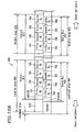
- Figure 12 shows locations of areas in a first defect management area 611 (DMA1).
- DMA1 first defect management area 611
- a defect list 1209 stored in the second DL storing area 702 contains two defect entries, i.e. , a defect entry A 1201 and a defect entry B 1202 .
- the defect entry A 1201 is information indicating that the defective area A 1110 of Figure 11 is replaced with the replacement area A 1111 .
- the defect entry B 1202 stores information indicating that the defective area B 1112 of Figure 11 is replaced with the replacement area B 1113.
- a replacement status flag contained in the defect entry A 1201 and a replacement status flag contained in the defect entry B 1202 each are 0. This is because a replacement status flag has a value 0 when a corresponding defective area is replaced with a replacement area, and has a value 1 when the defective area is not replaced and is registered.
- a defective sector layer number and a defective sector number indicate a number which permits to identify a recording layer and a sector number which permits to uniquely determine the location of a sector in a recording layer, respectively, as in Embodiment 1.
- the defective area A 1110 and its replacement area B 1111 are both contained in the first recording layer 53 , and therefore, a defective sector layer number 735 and a replacement sector layer number 737 contained in the defect entry A 1201 both indicate 1.
- the defective area B 1112 is contained in the second recording layer 54
- the replacement area B 1113 is contained in the first recording layer 53 . Therefore, a defective sector layer number 740 contained in the defect entry B 1202 indicates a value 2 representing the second recording layer 54 , and a replacement sector layer number 742 indicates a value 1 representing the first recording layer 53 . Note that the replacement sector numbers 737 and 742 represent a sector number which uniquely determines the starting position of a replacement area in a recording layer as do the defective sector numbers 735 and 740 .
- the defective area B 1112 in the second recording layer 54 is replaced with the replacement area B 1113 in the first recording layer 53. It is now assumed that, for example, a total of 1000 defective sectors can be present in two recording layers. If defect management was performed separately for each recording layer, a spare area(s) corresponding to at least 1000 sectors has to be allocated in each recording layer. In other words, a spare area(s) corresponding to a total of at least 2000 sectors is required for two recording layers. On the other hand, in Embodiment 2, a defect list for all recording layers is stored in a unified manner while a defective area in a certain recording layer can be replaced with a spare area in another recording layer.
- a spare area(s) corresponding to a total of 1000 sectors is required for the two recording layers (e.g., 500 sectors are provided in each of the two recording layers). Therefore, the volume of an area allocated as a spare area can be reduced, thereby making it possible to increase the volume of the user data area 602 .
- the multi-layered information recording medium 800 according to Embodiment 2 of the present invention has been heretofore described.
- the multi-layered information recording medium 800 according to Embodiment 2 of the present invention will be described below in terms of its effects in addition to the effects of the present invention described in Embodiment 1.
- Defect management information relating to all recording layers contained in a multi-layered information recording medium is managed by a single defect list, thereby making it possible to replace a defective area in a certain layer with a replacement area in a dif f erent layer. Therefore, even if defective areas occur intensively in a certain recording layer and all spare area in this layer are exhausted, spare areas in other recording layers can be used for replacement. Therefore, even if defective areas occur intensively in a specific recording layer due to degradation of a medium material or the like, spare areas in all recording layers can be efficiently used and the reliability of recorded data can be achieved. It is clearly appreciated that a method of using a spare DL in Embodiment 2 is the same as that in Embodiment 1, though a description thereof is omitted.
- the disc medium of Embodiment 2 is an opposite path disc in which recording and reproduction are performed from the inner periphery to the outer periphery of the first recording layer 53 and from the outer periphery to the inner periphery of the second recording layer 54 .
- defective areas can be similarly managed in a parallel path disc in which recording and reproduction are performed from the inner periphery to the outer periphery in all recording layers.
- Embodiment 3 of the present invention performs recording and reproduction using the multi-layered information recording mediums 600 and 800 described in Embodiments 1 and 2, respectively.
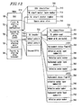
- FIG 13 is a block diagram showing the information recording/reproduction apparatus 500 according to Embodiment 3 of the present invention.
- the information recording/reproduction apparatus 500 comprises a disc motor 502, a preamplifier 508, a servo circuit 509, a binarization circuit 510, a modulation/demodulation circuit 511, an ECC circuit 512, a buffer 513, a CPU 514, an internal bus 534, and an optical head section 535.
- the multi-layered information recording medium 800 is loaded.
- the optical head section 535 comprises a lens 503 , an actuator 504 , a laser driving circuit 505 , a photodetector 506 , and a transport table 507 .
- Reference numeral 520 denotes a rotation detection signal.
- Reference numeral 521 denotes a disc motor driving signal.
- Reference numeral 522 denotes a laser emission permission signal.
- Reference numeral 523 denotes a light detection signal.
- Reference numeral 524 denotes a servo error signal.
- Reference numeral 525 denotes an actuator driving signal.
- Reference numeral 526 denotes a transport table driving signal.
- Reference numeral 527 denotes an analog data signal.
- Reference numeral 528 denotes a binarized data signal.
- Reference numeral 529 denotes a demodulated data signal.
- Reference numeral 530 denotes a corrected data signal.
- Reference numeral 531 denotes a stored data signal.
- Reference numeral 532 denotes an encoded data signal.
- Reference numeral 533 denotes a modulated data signal.
- the CPU 514 functions as a control section.
- the CPU 514 controls the entire operation of the information recording/reproduction apparatus 500 via the internal bus 534 according to an incorporated control program.
- the optical head section 535 can optically write information in the multi-layered information recording medium 800 from one side of the multi-layered information recording medium 800 .
- the optical head section 535 can optically read information from the multi-layered information recording medium 800.
- the CPU 514 controls execution of a defect management process using the optical head section 535 as described below.
- the laser driving circuit 505 In response to the laser emission permission signal 522 output from the CPU 514, the laser driving circuit 505 emits laser light 536 onto the multi-layered information recording medium 800 .
- the light reflected by the multi-layered information recording medium 800 is converted by the photodetector 506 to the light detection signal 523 .
- the light detection signal 523 is subjected to addition/subtraction in the preamplifier 508 so as to generate the servo error signal 524 and the analog data signal 527 .
- the analog data signal 527 is A/D (analog/digital) converted by the binarization circuit 510 to the binarized data signal 528 .
- the binarized data signal 528 is demodulated by the modulation/demodulation circuit 511 to generate the demodulated data signal 529 .
- the demodulated data signal 529 is converted by the ECC circuit 512 to the corrected data signal 530 which does not include any error.
- the corrected data signal 530 is stored in a buffer 513 .
- the servo circuit 509 outputs the actuator driving signal 525 based on the servo error signal 524 , thereby feeding a servo error back to the actuator 504 for focusing control or tracking control of the lens 503 .
- An error correction code is added by the ECC circuit 512 to the stored data signal 531 which is an output of data from the buffer 513 , so as to generate the encoded data signal 532 .
- the encoded data signal 532 is modulated by the modulation/demodulation circuit 511 to generate the modulated data signal 533 .
- the modulated data signal 533 is input to the laser driving circuit 505 so as to modulate the power of laser light.
- the information recording/reproduction apparatus 500 may be used as a peripheral device for a computer, such as a CD-ROM drive or the like, along with the computer.
- a host interface circuit (not shown) is additionally provided, and data is transmitted between a host computer (not shown) and the buffer 513 through a host interface bus (not shown) such as a SCSI or the like.
- an AV decoder/encoder circuit(not shown) isadditionallyprovided so as to compress a moving image or sound or decompress a compressed moving image or sound and the resultant data is transmitted between the host computer and the buffer 513 .
- a high level apparatus such as a host computer or the like, outputs location information specifying an area which recording and reproduction are to be performed, which information is represented by a logical sector number (LSN).
- LSN logical sector number
- Physical location information on the recording medium is represented by physical sector numbers (PSNs). It is now assumed that a PSN contains a sector layer number indicating a layer in which a sector is present, and a sector number with which it is possible to identify the location of a sector in a layer in which the sector is present.
- Figure 14 shows a flowchart 1400 for illustrating a procedure of obtaining defect management information in Embodiment 3 of the present invention.
- the CPU 514 instructs the servo circuit 509 to control the focal point of laser light so as to follow a track in a reference layer.
- the optical head section 535 reproduces a sector which stores disc information
- the CPU 514 confirms parameters and a format which are necessary for recording/reproduction of the multi-layered information recording medium 800 .
- the optical head section 535 reproduces a DDS area 700 stored in a reference layer.
- the reproduced DDS data is retained in a predetermined place of the buffer 513 .
- the CPU 514 determines whether or not a DL starting layer is present in a reference layer, by referencing a DL start sector layer number 711 in the DDS data within the buffer 513 . If the DL starting layer is present in the reference layer, the process proceeds to step 1406. If the DL starting layer is present in a recording layer other than the reference layer, the process proceeds to step 1405.
- the CPU 514 instructs the servo circuit 509 to control the focal point of laser light so as to follow a track in a recording layer indicated by the DL start sector layer number 711 .
- the optical head section 535 reads a predetermined size portion of a defect list from a sector indicated by the DL start sector number 712 .
- the read defect list is retained at a predetermined place in the buffer 513 .
- Figure 15 is a flowchart 1500 for illustrating a reproduction procedure of sectors according to Embodiment 3 of the present invention, wherein replacement is considered.
- this reproduction process assume that defect management information including DDS data and a defect list have already been retained in the buffer 513 .
- the CPU 514 converts LSNs, which are assigned to respective areas to be reproduced, to PSNs (detailed descriptions of this step will be described later with reference to Figure 16 ).
- the CPU 514 references to the layer number of the PSN of an area to be reproduced to determine whether or not a recording layer in which the focal point of laser light currently exists is identical to a recording layer to be reproduced. If identical, the process proceeds to step 1504; if not, the process proceeds to step 1503.
- the CPU 514 instructs the servo circuit 509 to control the focal point of the laser light 536 so as to follow a track in a recording layer to be reproduced.
- the optical head section 535 reproduces information recorded in a sector indicated by the PSN obtained at conversion step 1501.
- Figure 16 is a flowchart 1600 for illustrating a procedure of converting LSNs to PSNs (i.e., step 1501 of Figure 15 ) according to Embodiment 3 of the present invention.
- LSN is converted to PSN without considering the presence or absence of replacement, i.e., in a manner similar to when no defective sector is present.
- PSN Smallest PSN in the first user data area 15 + LSN .
- PSN Smallest PSN in the second user data area 16 + LSN - the total number of sectors in the first user data area 15 .
- a sector in the second user data area 16 to which the smallest PSN is assigned is located at the outermost perimeter portion of the second user data area 16 (i.e., being adjacent to the intermediate spare area 1002' ).
- the CPU 514 references defect entry data in a defect list to determine whether or not the PSN obtained in the above-described step matches a defective sector layer number and a defective sector number stored in the defect list. If registered, the process proceeds to step 1603; if not (i.e., no replacement), the process ends.
- the CPU 514 selects a replacement sector layer number and a replacement sector number indicated by a defect entry (i.e., a defective sector layer number and a defective sector number) indicating the PSN from defect entry data registered in the defect list.
- a defect entry i.e., a defective sector layer number and a defective sector number
- step 1603 when data is reproduced from the multi-layered information recording medium 600 ( Figure 6 ) having no spare area, the process indicated by step 1603 is omitted or the processes indicated by steps 1602 and 1603 are omitted.
- the information recording/reproduction apparatus 500 can reproduce data from a multi-layered information recording medium containing a defect management area.
- the reproduction operation of user data which is performed after the focal point of the laser light 536 has been moved to a recording layer to be accessed, is basically the same as the reproduction operation of user data performed for a single-layered information recording medium.
- any reproduction procedure for an information recording/reproducing apparatus designed for a single-layered disc can be used.
- Figure 17 is a flowchart for illustrating a procedure of updating defect management information according to Embodiment 3 of the present invention.
- this embodiment as an example of a formatting process for a multi-layered information recording medium, initialization and updating of defect management information will be described.
- the CPU 514 produces DDS data having predetermined definition values for a recording/reproduction apparatus and a defect list containing a DL header 720 in which the number of DL entries is set to be 0, in the buffer memory 513 .
- a DL start sector layer number 711 and a DL start sector number 712 in a DDS 700 before a formatting process are set in a newly produced DDS.
- step 1702 it is determined whether or not a recording layer indicated by the DL start sector layer number 712 is identical to a recording layer currently followed by the focal point of the laser light 536. If identical, the process proceeds to step 1704; if not, the process proceeds to step 1703.
- the CPU 514 instructs the servo circuit 509 to control the focal point of the laser light 536 so as to follow a track in a recording layer indicated by the DL start sector layer number 711 .
- the CPU 514 records a newly produced defect list in an area having a predetermined size which starts with a sector number indicated by the DL start sector number 712 .
- a defect list has been previously recorded in the area indicated by the DL start sector number 712 (e.g., the defect list 1209 ( Figure 12 ))
- the previously recorded defect list is updated to a newly produced defect list.
- the CPU 514 determines whether or not data is correctly recorded in a DL storing area. If correctly recorded, the process proceeds to step 1707. If not (the area is not usable), the process proceeds to step 1706.
- the determination of the correctness of data recording is carried out by reading data recorded in the DL storing area and judging whether or not the read data is identical to data to be recorded.
- the CPU 514 selects another usable DL storing area. Initially, the CPU 514 determines whether or not a defect management area (or a spare DL) of a recording layer, in which data is currently recorded, contains a usable DL storing area. In the same recording layer, a DL storing area having a radial position close to that of a currently used DL storing area is selected. If no DL storing area is usable in the same recording layer, the CPU 514 selects a usable DL storing area containing an unused spare DL storing area in an adjacent recording layer. The CPU 514 records a defect list, which has the same contents as those of a defect list stored in a DL storing area which has been determined to be unusable, in a newly selected DL storing area.
- the CPU 514 determines whether or not a track currently followed by the focal point of the laser light 536 is of the reference layer. If so, the process proceeds to step 1709; if not, the process proceeds to step 1708.
- the CPU 514 instructs the servo circuit 509 to control the focal point of the laser light 536 so as to follow a track in the reference layer.
- the CPU 514 records the starting PSN of a DL area (containing a DL storing area selected in step 1706), in which a defect list is recorded, in DDS data produced in the buffer memory 513 . Specifically, a DL start sector layer number 712 and a DL start sector number 712 are updated.
- the CPU 514 records the DDS data produced in the buffer memory 513 in a DDS area of a multi-layered information recording medium using the optical head section 535 .
- an area in which a defect list is recorded is not limited to a defect list storing area before a formatting process. It is clearly appreciated that, for example, all defect list storing areas before a formatting process may be made invalid, and the CPU 514 may record a defect list in a newly designated area.
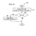
- Figure 18 is a flowchart 1800 for illustrating a recording procedure according to Embodiment 3 of the present invention, wherein replacement is considered.
- the CPU 514 converts LSNs, which specify sectors in which data is to be recorded, to PSNs (see Figure 21 ).
- the CPU 514 references to the layer number of a PSN to determine whether or not a recording layer currently followed by the focal point of the laser light 536 is identical to a recording layer in which data is to be recorded. If identical, the process proceeds to step 1804 ; if not, the process proceeds to step 1803.
- the CPU 514 instructs the servo circuit 509 to control the focal point of the laser light 536 so as to follow a track in the recording layer in which data is to be recorded.
- the CPU 514 records data in a sector indicated by the PSN obtained at step 1801 using the optical head section 535 .
- step 1805 the CPU 514 determines whether or not the data recording was successful at step 1804. If successful, the process proceeds to step 1807; if not, the CPU 514 determines that the sector in which it is attempted to record data is defective, and the process proceeds to step 1806.
- the CPU 514 allocates a spare sector for the sector which is determined to be defective.
- the CPU 514 replaces the defective area with an unused replacement area which contains a spare area at the shortest radial distance from the defective area and is present in a recording layer containing the defective area (in this case, the replacement area is a spare sector).
- the replacement area is a spare sector. For example, when the defective area is detected on the outer periphery of the first recording layer 53 ( Figure 11 ), a replacement area is allocated from the first intermediate spare area 1102 provided in the recording layer 53 . If the intermediate spare area 1102 in the first recording layer 53 contains no usable replacement area, a usable replacement area is allocated from the intermediate spare area 1102' of the second recording layer 54 .
- the intermediate spare area 1102' of the second recording layer 54 contains no usable replacement area, a usable replacement area is allocated from the head spare area 1101 of the first recording layer 53 .
- any one of spare areas in a multi-layered information recording medium is assigned as a replacement area.
- the CPU 514 determines whether or not a spare sector has been newly allocated at step 1806. If not, the recording process ends; if so, the process proceeds to step 1808.
- the newly allocated replacement sector is registered in the defect list stored in the buffer memory 513 .
- the defective sector is already registered in the defect list, only a replacement sector layer number and a replacement sector number are updated.
- the detected defective sector is added to the defect list.
- step 1806 When data is recorded in the multi-layered information recording medium 600 ( Figure 6 ) containing no spare area, the process indicated by step 1806 is omitted. In this case, information which is used to manage the detected defective sector is registered in the defect list.
- the information recording/reproduction apparatus 500 can record data in a multi-layered information recording medium having a defect management area.
- a spare sector can be allocated from a spare area provided in a recording layer different from a recording layer in which a defective sector is present.
- the information recording/reproduction apparatus 500 can allocate spare sectors in a manner that gives a greater weight to reduction of a seek time or in a manner that gives a greater weight to reduction of the time required for setting recording power.
- the recording operation of user data to the user data area which is performed after the focal point of laser light has been moved to a recording layer to be accessed, is basically the same as the recording operation of user data performed for a single-layered information recording medium.
- any recording procedure for an information recording/reproducing apparatus designed for a single-layered disc can be used.
- reproduction/recording of information and defect management are performed on a sector-by-sector basis
- the present invention is applicable even when reproduction/recording of information and defect management is performed on a block-by-block basis (a block contains a plurality of sectors), or on an ECC block-by-ECC block basis (an ECC block is a unit based on which an error correction code of, for example, a DVD disc is calculated).
- a block-by-block basis a block contains a plurality of sectors
- ECC block-by-ECC block basis an ECC block is a unit based on which an error correction code of, for example, a DVD disc is calculated.
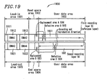
- FIG 19 is a diagram showing a multi-layered information recording medium 1900 according to Embodiment 4 of the present invention.
- the multi-layered information recording medium 1900 comprises two recording layers 55 and 56 .
- the multi-layered information recording medium 1900 comprises a user data area 1903 for recording user data.
- the upper recording layer ( 55 ) shown in Figure 19 is referred to as a first recording layer
- the lower recording layer ( 56 ) is referred to as a second recording layer.
- the first recording layer 55 is located at a predetermined distance from a surface of the multi-layered information recording medium 1900 through which data is read out (data read-out surface).
- the first recording layer 55 is referred to as a reference layer. This predetermined distance is equal to a distance from the data read-out surface of an optical disc comprising only one recording layer to the recording layer.
- a reference layer is predetermined among a plurality of recording layers.
- the first recording layer 55 contains, from the inner periphery to the outer periphery along the recording/reproduction direction of the multi-layered information recording medium 1900 , a lead-in area 1901 , a head spare area 1902 , and a first user data area 1931 which is a portion of the user data area 1903 .
- the second recording layer 56 contains, from the outer periphery to the inner periphery along the recording/reproduction direction of the multi-layered information recording medium 1900, a second user data area 1932 which is a portion of the user data area 1903 , an end spare area 1904 , and a lead-out area 1905 .
- the lead-in area 1901 contains a control data area 1911 for storing control information for the multi-layered information recording medium 1900 , and a first defect management area 1912 (DMA1) and a second defect management area 1913 (DMA2) for recording defect management information relating to a defective area.
- the head spare area 1902 and the end spare area 1904 contain a replacement area which may be used in place of a defective area in the user data area 1903 .
- the lead-out area 1905 contains a third defect management area 1921 (DMA3) and a fourth defect management area 1922 (DMA4) for recording defect management information relating to a defective area.
- the first defect management area 1912 (DMA1), the second defect management area 1913 (DMA2), the third defect management area 1921 (DMA3), and the fourth defect management area 1922 (DMA4) each store the same defect management information. This is because by duplicately recording the same defect management information in a plurality of areas in the multi-layered information recording medium 1900 , the reliability of the defect management information is improved.
- the user data area 1903 contains a first user data area 1931 and a second user data area 1932 .
- a defective area A 1915 is present in the first user data area 1931 .
- a defective area B 1924 is present in the second user data area 1932.
- the defective area A 1915 is replaced with a replacement area A 1914.
- the defective area B 1924 is replaced with a replacement area B 1923.
- the multi-layered information recording medium 1900 according to Embodiment 4 of the present invention contains four defect management areas having the same contents, thereby making it possible to obtain the reliability of defect management information. All of the four defect management areas are provided intensively on the inner periphery of the multi-layered information recording medium 1900 , thereby making it possible to minimize a distance over the optical head section is moved. According to this feature, the time required for the initial process of the multi-layered information recording medium 1900 can be advantageously reduced. Further, no defect management area is provided on the outer periphery, and therefore, the entire outer periphery of the multi-layered information recording medium 1900 can be used as a user data area. Therefore, a larger user data capacity can be obtained.
- a data structure of the first defect management area 1912 will be described with reference to Figure 20 .
- the first defect management area 1912 (DMA1), the second direct management area 1913 (DMA2), the third defect management area 1921, and the fourth direct management area 1922 each have the same defect management information.
- the first defect management area 1912 will be described and a description of the other defect management areas is omitted.
- Figure 20 shows a data structure of the first defect management area 1912 .
- a DDS area 2000 , first to fourth DL storing areas 2001 to 2004 , and a DL header area 2020 have the same data structure as that of the DDS area 700 , the first to fourth DL storing areas 701 to 704 , and the DL header area 720 , respectively, shown in Figure 7 , and a description thereof is omitted.
- a defect entry A 2021 and a defect entry B 2022 contained in a defect list 2009 will be described.
- the defect entry A 2021 contains defect management information relating to a defective area A 1915 ( Figure 19 ).
- the defective area A 1915 is replaced with a replacement area A 1914. Therefore, a replacement status 734 contained in the defect entry A 2021 indicates 0 which means the presence of replacement.
- a defective sector layer number 735 indicates a value 1 which means the first recording layer 55 .
- a defective sector number 736 indicates an identification number which permits to uniquely identify the defective area A 1915 in the first recording layer 55 .
- a replacement sector layer number 737 indicates a value 1.
- a replacement sector number 738 indicates an identification number which permits to uniquely identify the replacement area A 1914 in the first recording layer 55 .
- the defect entry B 2022 contains defect management information relating to a defective area B 1924 ( Figure 19 ).
- the defective area B 1924 is replaced with a replacement area B 1923 . Therefore, a replacement status 739 contained in the defect entry B 2022 indicates 0 which means the presence of replacement.
- a defective sector layer number 741 indicates a value 2 which means the second recording layer 56 .
- a defective sector number 741 indicates an identification number which permits to uniquely identify the defective area B 1924 in the second recording layer 56 .
- a replacement sector layer number 742 indicates a value 2.
- a replacement sector number 743 indicates an identification number which permits to uniquely identify the replacement area B 1923 in the second recording layer 56 .
- the disc medium of Embodiment 4 is an opposite path disc in which recording and reproduction are performed from the inner periphery to the outer periphery of the first recording layer 55 and from the outer periphery to the inner periphery of the second recording layer 56 .
- defective areas can be managed in a parallel path disc in which recording and reproduction are performed from the inner periphery to the outer periphery in all recording layers.
- two spare areas i.e., the head spare area 1902 and the end space area 1904 are provided in the multi-layered information recording medium 1900, however, either or both of them may be omitted.
- the multi-layered information recording medium 1900 having two recording layers has been described, however, even in the case of a multi-layered information recording medium having at least three recording layers, the above-described effect is obtained if a defect management area is provided on the inner periphery of a reference layer and the inner periphery of a recording layer other than the reference layer.
- a defect management area may be provided on the inner peripherys of all recording layers other than the reference layer.
- FIG 21 is a diagram showing a multi-layered information recording medium 2100 according to Embodiment 5 of the present invention.
- the multi-layered information recording medium 2100 comprises two recording layers 57 and 58 .
- the multi-layered information recording medium 2100 contains a user data area 2103 for recording user data.
- the user data area 2103 straddles a boundary of the first and second recording layers 57 and 58 .
- the upper recording layer ( 57 ) shown in Figure 21 is referred to as a first recording layer
- the lower recording layer ( 58 ) is referred to as a second recording layer.
- the first recording layer 57 is located at a predetermined distance from a surface of the multi-layered information recording medium 2100 through which data is read out (data read-out surface).
- the first recording layer 57 is referred to as a reference layer.
- This predetermined distance is equal to a distance from the data read-out surface of an optical disc comprising only one recording layer to the recording layer.
- a reference layer is predetermined among a plurality of recording layers.
- the first recording layer 57 contains, from the inner periphery to the outer periphery along the recording/reproduction direction of the multi-layered information recording medium 2100 , a lead-in area 2101 , a head spare area 2102 , and a first user data area 2131 which is a portion of the user data area 2103 .
- the second recording layer 58 contains, from the inner periphery to the outer periphery along the recording/reproduction direction of the multi-layered information recording medium 2100 , a second user data area 2132 which is a portion of the user data area 2103 , an end spare area 2104 , and a lead-out area 2105 .
- the lead-in area 2101 contains a control data area 2111 for storing control information for the multi-layered information recording medium 2100 , and a first defect management area 2112 (DMA1) and a second defect management area 2113 (DMA2) for recording defect management information relating to a defective area.
- the head spare area 2102 and the end spare area 2104 contain a replacement area which may be used in place of a defective area in the user data area 2103 .
- the lead-out area 2105 contains a third defect management area 2121 (DMA3) and a fourth defect management area 2122 (DMA4) for recording defect management information relating to a defective area.
- the first defect management area 2112 (DMA1), the second defect management area 2113 (DMA2), the third defect management area 2121 (DMA3), and the fourth defect management area 2122 (DMA4) each store the same defect management information. This is because by duplicately recording the same defect management information in a plurality of areas in the multi-layered information recording medium 2100 , the reliability of the defect management information is improved.
- the user data area 2103 contains a first user data area 2131 and a second user data area 2132 .
- a defective area A 2115 is present in the first user data area 2131 .
- a defective area B 2124 is present in the second user data area 2132 .
- the defective area A 2115 is replaced with a replacement area A 2114 .
- the defective area B 2124 is replaced with a replacement area B 2123 .
- the multi-layered information recording medium 2100 according to Embodiment 5 of the present invention contains defect management areas on the inner periphery in the first recording layer 57 while containing direct management areas on the outer periphery in the second layer 58 , thereby dramatically improving the possibility that any direct management area on either the inner periphery or the outer periphery can be used for reproduction even if a stain (e.g., a fingerprint or the like) or a scratch is present on the multi-layered information recording medium 2100 ; and making it possible to obtain the reliability of defect management information.
- Defect management areas are provided on only one of the inner periphery and the outer periphery of each recording layer, thereby obtaining a larger usable area as a user data area. Therefore, a larger user data capacity can be obtained.
- a data structure of the defect management area in Example 5 is the same as that of Example 4 described with reference to Figure 20 , and a description thereof is omitted.
- the reliability of defect management information can be improved while a larger user data capacity is obtained.
- the disc medium of Embodiment 5 is a parallel path disc in which recording and reproduction are performed from the inner periphery to the outer periphery of the first recording layer 57 and from the inner periphery to the outer periphery of the second recording layer 58 .
- defective areas can be managed in an opposite path disc in which recording and reproduction are performed from the inner periphery to the outer periphery in the recording layer 57 and from the outer periphery to the inner periphery in the recording layer 58 .
- two spare areas i.e., the head spare area 2102 and the end space area 2104 are provided in the multi-layered information recording medium 2100 , however, either or both of them may be omitted. If none of the spare areas are present in the multi-layered information recording medium 2100 , a defect list is used to manage information relating to a defective area with no replacement area allocated.
- the multi-layered information recording medium 2100 having two recording layers has been described, however, even in the case of a multi-layered information recording medium having at least three recording layers, the above-described effect is obtained if a defect management area is provided on the inner periphery of a reference layer and the inner periphery of a recording layer other than the reference layer.
- FIG 22 is a diagram showing a multi-layered information recording medium 2200 according to Embodiment 6 of the present invention.
- the multi-layered information recording medium 2200 comprises two recording layers 59 and 60 .
- the multi-layered information recording medium 2200 contains a user data area 2203 for recording user data.
- the user data area 2203 straddles a boundary of the first and second recording layers 59 and 60 .
- the upper recording layer ( 59 ) shown in Figure 21 is referred to as a first recording layer
- the lower recording layer ( 60 ) is referred to as a second recording layer.
- the first recording layer 59 is located at a predetermined distance from a surface of the multi-layered information recording medium 2200 through which data is read out (data read-out surface).
- the first recording layer 59 is referred to as a reference layer.
- This predetermined distance is equal to a distance from the data read-out surface of an optical disc comprising only one recording layer to the recording layer.
- a reference layer is predetermined among a plurality of recording layers.
- the first recording layer 59 contains, from the inner periphery to the outer periphery along the recording/reproduction direction of the multi-layered information recording medium 2200 , a lead-in area 2201 , a head spare area 2202 , a first user data area 2231 which is a portion of the user data area 2203 , a first intermediate spare area 2204 , and a first lead-out area 2205 .
- the second recording layer 60 contains, from the inner periphery to the outer periphery along the recording/reproduction direction of the multi-layered information recording medium 2200 , a second lead-in area 2206 , a second intermediate spare area 2207 , a second user data area 2232 which is a portion of the user data area 2203 , an end spare area 2208 , and a second lead-out area 2209 .
- the first lead-in area 2201 contains a control data area 2211 for storing control information for the multi-layered information recording medium 2200 , and a first defect management area 2212 (DMA1) and a second defect management area 2213 (DMA2) for recording defect management information relating to a defective area.
- the head spare area 2202 , the first spare area 2204, the second spare area 2207 , and the end spare area 2104 contain a replacement area which may be used in place of a defective area in the user data area 2203 .
- the first lead-out area 2205 contains a third defect management area 2216 (DMA3) and a fourth defect management area 2217 (DMA4) for recording defect management information relating to a defective area.
- the second lead-in area 2206 contains a control data area 2211 for storing control information for the multi-layered information recording medium 2200 , and a fifth defect management area 2221 (DMA5) and a sixth defect management area 2222 (DMA6) for recording defect management information relating to a defective area.
- the second lead-out area 2209 contains a seventh defect management area 2223 (DMA7) and an eighth defect management area 2224 (DMA8) for recording defect management information relating to a defective area.
- the first defect management area 2212 (DMA1), the second defect management area 2213 (DMA2), the third defect management area 2216 (DMA3), the fourth defect management area 2217 (DMA4), the fifth defect management area 2221 (DMA5), the sixth defect management area 2222 (DMA6), the seventh defect management area 2223 (DMA7), and the eighth defect management area 2224 (DMA8) each store the same defect management information. This is because by duplicately recording the same defect management information in a plurality of areas in the multi-layered information recording medium 2200 , the reliability of the defect management information is improved.
- the user data area 2203 contains a first user data area 2231 and a second user data area 2232 .
- a defective area A 2215 is present in the first user data area 2231 .
- a defective area B 2225 is present in the second user data area 2232 .
- the defective area A 2215 is replaced with a replacement area A 2214 .
- the defective area B 2225 is replaced with a replacement area B 2226 .
- the multi-layered information recording medium 2200 according to Embodiment 6 of the present invention contains defect management areas on the inner periphery and the outer periphery in both the first recording layer 59 and the second recording layer 60 , thereby making it possible to obtain the reliability of defect management information.
- defect management information For example, the possibility that any direct management area on either the inner periphery or the outer periphery can be used for reproduction even if a stain (e.g., a fingerprint or the like) or a scratch is present on the multi-layered information recording medium 2100 , is dramatically improved, thereby enhancing the reliability of defect management information.
- a data structure of the defect management area in Example 6 is the same as that of Example 4 described with reference to Figure 20 , and a description thereof is omitted.
- the reliability of defect management information can be significantly improved.
- the disc medium of Embodiment 6 is a parallel path disc in which recording and reproduction are performed from the inner periphery to the outer periphery of the first recording layer 59 and from the inner periphery to the outer periphery of the second recording layer 60 .
- defective areas can be managed in an opposite path disc in which recording and reproduction are performed from the inner periphery to the outer periphery in the recording layer 59 and from the outer periphery to the inner periphery in the recording layer 60 .
- Embodiment 6 four spare areas, i.e., the head spare area 2202 , the first intermediate spare area 2204 , the second intermediate spare area 2207 , and the end space area 2208 , are provided in the multi-layered information recording medium 2200 , however, any or all of them may be omitted. If none of the spare areas are present in the multi-layered information recording medium 2200 , a defect list is used to manage information relating to a defective area with no replacement area allocated.
- the multi-layered information recording medium 2200 having two recording layers has been described, however, even in the case of a multi-layered information recording medium having at least three recording layers, the above-described effect is obtained if a defect management area is provided on the inner periphery and the outer periphery of a reference layer and the inner periphery and the outer periphery of a recording layer other than the reference layer.
- control information areas such as an area for storing recording and reproduction parameters for the multi-layered information recording medium, an area for storing information relating to defect management, or the like, is provided in a single recording layer, thereby making it possible to access control information at high speed.
- all defect management information for all recording layers is stored in a single recording layer, thereby making it possible to access defect management information at high speed.
- a spare defect list storing area is provided in a recording layer other than a recording layer storing defect management information, thereby making it possible to improve the reliability of defect management information.
- a disc definition structure area containing information indicating the location of a defect list and a spare defect list area which may store the defect list are located at substantially the same radial positions, thereby making it possible to access the defect list at high speed.
- all defect lists in all recording layers are managed in a unified manner, thereby making it possible to efficiently use a defect list area even if the incidence of defective areas varies between each recording layer.
- a detected defective area is replaced with a spare area in any recording layer, thereby making it possible to effectively use spare areas and improve the reliability of data.
- a defect management area is provided on one of the inner periphery and the outer periphery of each recording layer, thereby making it possible to obtain a larger user data capacity.
- the information reproduction method and the information reproduction apparatus of the present invention it is possible to reproduce information from a multi-layered information recording medium containing defect management information relating to a plurality of recording layer.
- the information recording method and the information recording apparatus of the present invention it is possible to record information in a multi-layered information recording medium containing defect management information relating to a plurality of recording layer.
Landscapes
- Engineering & Computer Science (AREA)
- Signal Processing (AREA)
- Optical Recording Or Reproduction (AREA)
- Signal Processing For Digital Recording And Reproducing (AREA)
Claims (36)
- Mehrschichtiges optisches Informationsaufzeichnungsmedium, umfassend:eine Mehrzahl von Aufzeichnungsschichten (51, 52, 53, 54, 55, 56, 57, 58, 59, 60);einen Benutzerdatenbereich (602, 1110, 1903, 2103, 2203) zum Aufzeichnen von Benutzerdaten, der in mindestens zweien der Mehrzahl von Aufzeichnungsschichten vorgesehen ist; undeinen Fehlerlistenspeicherbereich (701, 702, 703, 704) zum Speichern einer Fehlerliste (709), bei der es sich um Informationen zum Verwalten eines fehlerhaften Bereichs (630, 631, 1110, 1112, 1915, 1924, 2115, 2124, 2215, 2225) handelt, der im Benutzerdatenbereich erkannt wird,dadurch gekennzeichnet, dass der Fehlerlistenspeicherbereich in einer vorgegebenen Schicht (51, 53, 55, 57, 59) der Mehrzahl von Aufzeichnungsschichten vorgesehen ist,es sich bei der Fehlerliste um Informationen zum Verwalten eines fehlerhaften Bereichs, der in der vorgegebenen Schicht erkannt wird, und eines fehlerhaften Bereichs handelt, der in einer anderen Aufzeichnungsschicht (52, 54, 56, 58, 60) als der vorgegebenen Schicht erkannt wird, undmindestens eine andere der Mehrzahl von Aufzeichnungsschichten als die vorgegebene Schicht einen Reserve-Fehlerlistenspeicherbereich (620, 621, 622, 623) umfasst, der verwendet wird, um die Fehlerliste aufzuzeichnen, wenn der Fehlerlistenspeicherbereich nicht verwendet werden kann.
- Mehrschichtiges optisches Informationsaufzeichnungsmedium nach Anspruch 1, wobei der Fehlerlistenspeicherbereich ferner einen Fehlerlistenlageinformations-Speicherbereich (700) zum Speichern von Fehlerlistenlageinformationen umfasst, welche die Lage eines die Fehlerliste speichernden Bereichs neben dem Fehlerlistenspeicherbereich und dem Reserve-Fehlerlistenspeicherbereich anzeigen.
- Mehrschichtiges optisches Informationsaufzeichnungsmedium nach Anspruch 2, ferner umfassend:einen Fehlerlistenlageinformations-Speicherbereich zum Speichern von Fehlerlistenlageinformationen, welche die Lage des Fehlerlistenspeicherbereichs anzeigen,wobei der Fehlerlistenlageinformations-Speicherbereich in einer der Mehrzahl von Aufzeichnungsschichten vorgesehen ist, die als eine Referenzschicht (51, 53, 55, 57, 59) vorbestimmt ist.
- Mehrschichtiges optisches Informationsaufzeichnungsmedium nach Anspruch 3, wobei die Referenzschicht eine der Mehrzahl von Aufzeichnungsschichten ist, welche in einem vorbestimmten Abstand von der Datenauslesefläche des mehrschichtigen Informationsaufzeichnungsmediums angeordnet ist.
- Mehrschichtiges optisches Informationsaufzeichnungsmedium nach Anspruch 3, wobei die Referenzschicht eine der Mehrzahl von Aufzeichnungsschichten ist, welche in einem kürzesten Abstand von der Datenauslesefläche des mehrschichtigen Informationsaufzeichnungsmediums angeordnet ist.
- Mehrschichtiges optisches Informationsaufzeichnungsmedium nach Anspruch 3, wobei die Referenzschicht eine der Mehrzahl von Aufzeichnungsschichten ist, welche in einem längsten Abstand von der Datenauslesefläche des mehrschichtigen Informationsaufzeichnungsmediums angeordnet ist.
- Mehrschichtiges optisches Informationsaufzeichnungsmedium nach Anspruch 2, wobei die Fehlerlistenlageinformationen die Lage eines aktuellen, die Fehlerliste speichernden Bereichs neben dem Fehlerlistenspeicherbereich und dem Reserve-Fehlerlistenspeicherbereich anzeigen.
- Mehrschichtiges optisches Informationsaufzeichnungsmedium nach Anspruch 7, wobei die Fehlerlistenlageinformationen die Lage eines aktuellen, die Fehlerliste speichernden Bereichs durch eine Schichtnummer zum Unterscheiden der Mehrzahl von Aufzeichnungsschichten voneinander und eine schichtinterne Adresse zum Anzeigen einer Position in jeder der Mehrzahl von Aufzeichnungsschichten anzeigen.
- Mehrschichtiges optisches Informationsaufzeichnungsmedium nach Anspruch 7, wobei der Fehlerlistenspeicherbereich und der Reserve-Fehlerlistenspeicherbereich im Wesentlichen an den gleichen radialen Positionen im mehrschichtigen Informationsaufzeichnungsmedium angeordnet sind.
- Mehrschichtiges optisches Informationsaufzeichnungsmedium nach Anspruch 7, ferner umfassend eine Mehrzahl von zusätzlichen Fehlerlistenspeicherbereichen zum Speichern einer Fehlerliste mit den gleichen Inhalten wie den Inhalten der Fehlerliste, die im Fehlerlistenspeicherbereich gespeichert ist.
- Mehrschichtiges optisches Informationsaufzeichnungsmedium nach Anspruch 1, wobei die Fehlerliste die Lage des erkannten mindesten einen fehlerhaften Bereichs durch eine Schichtnummer zum Unterscheiden der Mehrzahl von Aufzeichnungsschichten voneinander und eine schichtinterne Adresse zum Anzeigen einer Position in jeder der Mehrzahl von Aufzeichnungsschichten anzeigt.
- Mehrschichtiges optisches Informationsaufzeichnungsmedium nach Anspruch 1, ferner umfassend einen Reservebereich (1101, 1102, 1102', 1103, 1902, 1904, 2102, 2104, 2202, 2204, 2207, 2208), der mindestens einen Ersatzbereich (1111, 1113, 1914, 1923, 2114, 2123, 2214, 2226) enthält, wobei, wenn mindestens ein fehlerhafter Bereich im Benutzerdatenbereich erkannt wird, der mindestens eine Ersatzbereich anstelle des mindestens einen fehlerhaften Bereichs verwendet werden kann.
- Mehrschichtiges optisches Informationsaufzeichnungsmedium nach Anspruch 12, wobei, wenn der fehlerhafte Bereich durch den Ersatzbereich ersetzt wird, die Fehlerliste die Lage des erkannten fehlerhaften Bereichs und die Lage des Ersatzbereichs durch jeweilige Schichtnummern zum Unterscheiden der Mehrzahl von Aufzeichnungsschichten voneinander und jeweilige schichtinterne Adressen zum Anzeigen einer Position in jeder der Mehrzahl von Aufzeichnungsschichten anzeigt.
- Mehrschichtiges optisches Informationsaufzeichnungsmedium nach Anspruch 1, wobei der Fehlerlistenspeicherbereich in einer der Mehrzahl von Aufzeichnungsschichten vorgesehen ist,
das mehrschichtige optische Informationsaufzeichnungsmedium ferner einen zusätzlichen Fehlerlistenspeicherbereich zum Speichern einer Fehlerliste mit den gleichen Inhalten wie den Inhalten der Fehlerliste umfasst, die im Fehlerlistenspeicherbereich gespeichert ist, und
der zusätzliche Fehlerlistenspeicherbereich in einer anderen der Mehrzahl von Aufzeichnungsschichten vorgesehen ist. - Mehrschichtiges optisches Informationsaufzeichnungsmedium nach Anspruch 14, ferner umfassend:einen ersten Fehlerlistenlageinformations-Speicherbereich zum Speichern von ersten Fehlerlistenlageinformationen, welche die Lage des Fehlerlistenspeicherbereichs anzeigen; undeinen zweiten Fehlerlistenlageinformations-Speicherbereich zum Speichern von Fehlerlistenlageinformationen, welche die Lage des zusätzlichen Fehlerlistenspeicherbereichs anzeigen,wobei der ersten Fehlerlistenlageinformations-Speicherbereich in der gleichen Aufzeichnungsschicht wie der vorgesehen ist, in welcher der Fehlerlistenspeicherbereich vorgesehen ist, undder zweite Fehlerlistenlageinformations-Speicherbereich in der gleichen Aufzeichnungsschicht wie der vorgesehen ist, in welcher der zusätzliche Fehlerlistenspeicherbereich vorgesehen ist.
- Mehrschichtiges optisches Informationsaufzeichnungsmedium nach Anspruch 15, wobei die Aufzeichnungsschicht, in welcher der Fehlerlistenspeicherbereich vorgesehen ist, einen ersten Fehlerverwaltungsbereich umfasst, welcher den Fehlerlistenspeicherbereich und den ersten Fehlerlistenlageinformations-Speicherbereich enthält,
die Aufzeichnungsschicht, in welcher der zusätzliche Fehlerlistenspeicherbereich vorgesehen ist, einen zweiten Fehlerverwaltungsbereich umfasst, welcher den zusätzlichen Fehlerlistenspeicherbereich und den zweiten Fehlerlistenlageinformations-Speicherbereich enthält,
logische Adressen dem Benutzerdatenbereich zugeordnet sind,
ein Bereich des Benutzerdatenbereichs, dem die kleinste logische Adresse zugeordnet ist, in der Aufzeichnungsschicht vorgesehen ist, in welcher der Fehlerlistenspeicherbereich vorgesehen ist,
ein Bereich des Benutzerdatenbereichs, dem die größte logische Adresse zugeordnet ist, in der Aufzeichnungsschicht vorgesehen ist, in welcher der zusätzliche Fehlerlistenspeicherbereich vorgesehen ist,
der erste Fehlerverwaltungsbereich benachbart zu dem Bereich ist, dem die kleinste logische Adresse zugeordnet ist, und
der zweite Fehlerverwaltungsbereich benachbart zu dem Bereich ist, dem die größte logische Adresse zugeordnet ist. - Vorrichtung (500) zum Wiedergeben von Informationen, die auf einem mehrschichtigen optischen Informationsaufzeichnungsmedium nach Anspruch 1 aufgezeichnet sind,
dadurch gekennzeichnet, dass die Vorrichtung einen Fehlerlistenwiedergabeabschnitt (514) zum Wiedergeben der Fehlerliste umfasst, die im Fehlerlistenspeicherbereich gespeichert ist, der in einer vorgegebenen Schicht der Mehrzahl von Aufzeichnungsschichten vorgesehen ist, und
der Fehlerlistenwiedergabeabschnitt so ausgelegt ist, dass er die Fehlerliste aus dem Reserve-Fehlerlistenspeicherbereich wiedergibt, wenn der Fehlerlistenspeicherbereich nicht verwendet werden kann. - Vorrichtung nach Anspruch 17, wobei das mehrschichtige optische Informationsaufzeichnungsmedium ferner umfasst:einen Fehlerlistenlageinformations-Speicherbereich (700) zum Speichern von Fehlerlistenlageinformationen, welche die Lage des Fehlerlistenspeicherbereichs anzeigen,wobei der Fehlerlistenlageinformations-Speicherbereich in einer der Mehrzahl von Aufzeichnungsschichten vorgesehen ist, die als eine Referenzschicht (51, 53, 55, 57, 59) vorbestimmt ist, undder Fehlerlistenwiedergabeabschnitt so ausgelegt ist, dass er die Lage des Fehlerlistenspeicherbereichs durch Wiedergeben der Fehlerlistenlageinformationen identifiziert, die im Fehlerlistenlageinformations-Speicherbereich gespeichert sind.
- Vorrichtung nach Anspruch 17, ferner umfassend einen Benutzerdatenwiedergabeabschnitt (514) zum Wiedergeben der Benutzerdaten, die im Benutzerdatenbereich aufgezeichnet sind,
wobei das mehrschichtige optische Informationsaufzeichnungsmedium ferner umfasst:einen Reservebereich (1101, 1102, 1102', 1103, 1902, 1904, 2102, 2104, 2202, 2204, 2207, 2208), der mindestens einen Ersatzbereich (1111, 1113, 1914, 1923, 2114, 2123, 2214, 2226) enthält, wobei, wenn mindestens ein fehlerhafter Bereich im Benutzerdatenbereich erkannt wird, der mindestens eine Ersatzbereich anstelle des mindestens einen fehlerhaften Bereichs verwendet werden kann,wobei die Fehlerliste anzeigt, dass ein fehlerhafter Bereich, der im Benutzerdatenbereich vorhanden ist, durch den Ersatzbereich ersetzt wird, der im Reservebereich enthalten ist,wobei der Benutzerdatenwiedergabeabschnitt so ausgelegt ist, dass er Benutzerdaten aus dem Ersatzbereich, der durch die Fehlerliste angezeigt wird, statt aus dem fehlerhaften Bereich wiedergibt, der durch die Fehlerliste angezeigt wird. - Vorrichtung (500) zum Aufzeichnen von Informationen auf einem mehrschichtigen optischen Informationsaufzeichnungsmedium nach Anspruch 1,
dadurch gekennzeichnet, dass die Vorrichtung einen Fehlerlistenaufzeichnungsabschnitt (514) zum Aufzeichnen der Fehlerliste umfasst, die im Fehlerlistenspeicherbereich gespeichert ist, der in einer vorgegebenen Schicht der Mehrzahl von Aufzeichnungsschichten vorgesehen ist, und
der Fehlerlistenaufzeichnungsabschnitt so ausgelegt ist, dass er die Fehlerliste im Reserve-Fehlerlistenspeicherbereich aufzeichnet, wenn der Fehlerlistenspeicherbereich nicht verwendet werden kann. - Vorrichtung nach Anspruch 20, wobei das mehrschichtige optische Informationsaufzeichnungsmedium einen zusätzlichen Fehlerlistenspeicherbereich umfasst, der anstelle des Fehlerlistenbereichs verwendet werden kann, wenn der Fehlerlistenbereich nicht verwendet werden kann,
wobei der Fehlerlistenaufzeichnungsabschnitt so ausgelegt ist, dass er eine Fehlerliste mit den gleichen Inhalten wie den Inhalten einer Fehlerliste, die im Fehlerlistenspeicherbereich gespeichert ist, in den zusätzlichen Fehlerlistenspeicherbereich aufzeichnet, wenn der Fehlerlistenspeicherbereich nicht verwendet werden kann. - Vorrichtung nach Anspruch 21, wobei das mehrschichtige optische Aufzeichnungsmedium ferner Fehlerlistenlageinformationen umfasst, welche die Lage einer Fehlerliste anzeigen,
wobei der Fehlerlistenaufzeichnungsabschnitt so ausgelegt ist, dass er die Fehlerlistenlageinformationen aktualisiert, so dass die Fehlerlistenlageinformationen den zusätzlichen Fehlerlistenspeicherbereich anzeigen, wenn der zusätzliche Fehlerlistenspeicherbereich anstelle des Fehlerlistenspeicherbereichs verwendet wird. - Vorrichtung nach Anspruch 21, wobei das mehrschichtige optische Informationsaufzeichnungsmedium ferner umfasst:einen Fehlerverwaltungsbereich, der in einer der Mehrzahl von Aufzeichnungsschichten vorgesehen ist; undeinen Reserve-Fehlerlistenspeicherbereich, der in einer anderen der Mehrzahl von Aufzeichnungsschichten vorgesehen ist,wobei der Fehlerverwaltungsbereich eine Mehrzahl von Fehlerlistenspeicherbereichen umfasst,der Reserve-Fehlerverwaltungsbereich eine Mehrzahl von zusätzlichen Fehlerlistenspeicherbereichen umfasst,der Fehlerlistenspeicherbereich einer der Mehrzahl von Fehlerlistenspeicherbereichen ist,der zusätzliche Fehlerlistenspeicherbereich einer der Mehrzahl von zusätzlichen Fehlerlistenspeicherbereichen ist, undder zusätzliche Fehlerlistenspeicherbereich anstelle des Fehlerlistenspeicherbereichs verwendet wird, wenn keiner der Mehrzahl von Fehlerlistenspeicherbereichen verwendet werden kann.
- Vorrichtung nach Anspruch 21, wobei der Fehlerlistenspeicherbereich in einer der Mehrzahl von Aufzeichnungsschichten vorgesehen ist, und
der zusätzliche Fehlerlistenspeicherbereich in der gleichen Aufzeichnungsschicht wie der vorgesehen ist, in welcher der Fehlerlistenspeicherbereich vorgesehen ist. - Vorrichtung nach Anspruch 21, wobei der Fehlerlistenspeicherbereich in einer der Mehrzahl von Aufzeichnungsschichten vorgesehen ist, und
der zusätzliche Fehlerlistenspeicherbereich in einer anderen der Mehrzahl von Aufzeichnungsschichten vorgesehen ist. - Vorrichtung nach Anspruch 20, wobei das mehrschichtige optische Informationsaufzeichnungsmedium ferner umfasst:einen Reservebereich (1101, 1102, 1102', 1103, 1902, 1904, 2102, 2104, 2202, 2204, 2207, 2208), der mindestens einen Ersatzbereich (1111, 1113, 1914, 1923, 2114, 2123, 2214, 2226) enthält, wobei, wenn mindestens ein fehlerhafter Bereich im Benutzerdatenbereich erkannt wird, der mindestens eine Ersatzbereich anstelle des mindestens einen fehlerhaften Bereichs verwendet werden kann,wobei der Fehlerlistenaufzeichnungsabschnitt so ausgelegt ist, dass er den fehlerhaften Bereich, der im Benutzerdatenbereich vorhanden ist, durch den Ersatzbereich ersetzt, der im Reservebereich enthalten ist.
- Verfahren zur Wiedergabe von Informationen, die auf einem mehrschichtigen optischen Informationsaufzeichnungsmedium nach Anspruch 1 aufgezeichnet sind,
dadurch gekennzeichnet, dass das Verfahren die Schritte des Wiedergebens der Fehlerliste aus dem Fehlerlistenspeicherbereich, der in einer vorgegebenen Schicht der Mehrzahl von Aufzeichnungsschichten vorgesehen ist, und Wiedergeben der Fehlerliste aus dem Reserve-Fehlerlistenspeicherbereich umfasst, wenn der Fehlerlistenspeicherbereich nicht verwendet werden kann. - Verfahren nach Anspruch 27, wobei das mehrschichtige optische Informationsaufzeichnungsmedium ferner umfasst:einen Fehlerlistenlageinformations-Speicherbereich (700) zum Speichern von Fehlerlistenlageinformationen, welche die Lage des Fehlerlistenspeicherbereichs anzeigen,wobei der Fehlerlistenlageinformations-Speicherbereich in einer der Mehrzahl von Aufzeichnungsschichten vorgesehen ist, die als eine Referenzschicht (51, 53, 55, 57, 59) vorbestimmt ist,das Verfahren ferner ein Identifizieren der Lage des Fehlerlistenspeicherbereichs durch Wiedergeben der Fehlerlistenlageinformationen umfasst, die im Fehlerlistenlageinformations-Speicherbereich gespeichert sind.
- Verfahren nach Anspruch 27, wobei das mehrschichtige optische Informationsaufzeichnungsmedium ferner umfasst:einen Reservebereich (1101, 1102, 1102', 1103, 1902, 1904, 2102, 2104, 2202, 2204, 2207, 2208), der mindestens einen Ersatzbereich (1111, 1113, 1914, 1923, 2114, 2123, 2214, 2226) enthält, wobei, wenn mindestens ein fehlerhafter Bereich im Benutzerdatenbereich erkannt wird, der mindestens eine Ersatzbereich anstelle des mindestens einen fehlerhaften Bereichs verwendet werden kann,wobei die Fehlerliste anzeigt, dass ein fehlerhafter Bereich, der im Benutzerdatenbereich vorhanden ist, durch den Ersatzbereich ersetzt wird, der im Reservebereich enthalten ist,wobei das Verfahren ferner ein Wiedergeben von Benutzerdaten aus dem Ersatzbereich, der durch die Fehlerliste angezeigt wird, statt aus dem fehlerhaften Bereich umfasst, der durch die Fehlerliste angezeigt wird.
- Verfahren zur Aufzeichnung von Informationen auf einem mehrschichtigen optischen Informationsaufzeichnungsmedium nach Anspruch 1,
dadurch gekennzeichnet, dass das Verfahren die Schritte des Aufzeichnens der Fehlerliste im Fehlerlistenspeicherbereich, der in einer vorgegebenen Schicht der Mehrzahl von Aufzeichnungsschichten vorgesehen ist, und Aufzeichnen der Fehlerliste im Reserve-Fehlerlistenspeicherbereich umfasst, wenn der Fehlerlistenspeicherbereich nicht verwendet werden kann. - Verfahren nach Anspruch 30, wobei das mehrschichtige optische Informationsaufzeichnungsmedium ferner einen zusätzlichen Fehlerlistenspeicherbereich umfasst, der anstelle des Fehlerlistenspeicherbereichs verwendet werden kann, wenn der Fehlerlistenspeicherbereich nicht verwendet werden kann,
wobei das Verfahren ferner ein Aufzeichnen einer Fehlerliste mit den gleichen Inhalten wie den Inhalten einer Fehlerliste, die im Fehlerlistenspeicherbereich gespeichert ist, in den zusätzlichen Fehlerlistenspeicherbereich umfasst, wenn der Fehlerlistenspeicherbereich nicht verwendet werden kann. - Verfahren nach Anspruch 31, wobei das mehrschichtige optische Informationsaufzeichnungsmedium ferner umfasst:einen Fehlerlistenlageinformations-Speicherbereich (700) zum Speichern von Fehlerlistenlageinformationen, welche die Lage einer Fehlerliste anzeigen,wobei der Fehlerlistenlageinformations-Speicherbereich in einer der Mehrzahl von Aufzeichnungsschichten vorgesehen ist, die als eine Referenzschicht (51, 53, 55, 57, 59) vorbestimmt ist,wobei das Verfahren ferner ein Aktualisieren der Fehlerlistenlageinformationen umfasst, so dass die Fehlerlistenlageinformationen den zusätzlichen Fehlerlistenspeicherbereich anzeigen, wenn der zusätzliche Fehlerlistenspeicherbereich anstelle des Fehlerlistenspeicherbereichs verwendet wird.
- Verfahren nach Anspruch 31, wobei das mehrschichtige optische Informationsaufzeichnungsmedium ferner umfasst:einen Fehlerverwaltungsbereich, der in einer der Mehrzahl von Aufzeichnungsschichten vorgesehen ist; undder Reserve-Fehlerlistenspeicherbereich, der in einer anderen der Mehrzahl von Aufzeichnungsschichten vorgesehen ist,wobei der Fehlerverwaltungsbereich eine Mehrzahl von Fehlerlistenspeicherbereichen umfasst,der Reserve-Fehlerverwaltungsbereich eine Mehrzahl von zusätzlichen Fehlerlistenspeicherbereichen umfasst,der Fehlerlistenspeicherbereich einer der Mehrzahl von Fehlerlistenspeicherbereichen ist,der zusätzliche Fehlerlistenspeicherbereich einer der Mehrzahl von zusätzlichen Fehlerlistenspeicherbereichen ist, undder zusätzliche Fehlerlistenspeicherbereich anstelle des Fehlerlistenspeicherbereichs verwendet wird, wenn keiner der Mehrzahl von Fehlerlistenspeicherbereichen verwendet werden kann.
- Verfahren nach Anspruch 31, wobei der Fehlerlistenspeicherbereich in einer der Mehrzahl von Aufzeichnungsschichten vorgesehen ist, und
der zusätzliche Fehlerlistenspeicherbereich in der gleichen Aufzeichnungsschicht wie der vorgesehen ist, in welcher der Fehlerlistenspeicherbereich vorgesehen ist. - Verfahren nach Anspruch 31, wobei der Fehlerlistenspeicherbereich in einer der Mehrzahl von Aufzeichnungsschichten vorgesehen ist, und
der zusätzliche Fehlerlistenspeicherbereich in einer anderen der Mehrzahl von Aufzeichnungsschichten vorgesehen ist. - Verfahren nach Anspruch 30, wobei das mehrschichtige optische Informationsaufzeichnungsmedium ferner umfasst:einen Reservebereich (1101, 1102, 1102', 1103, 1902, 1904, 2102, 2104, 2202, 2204, 2207, 2208), der mindestens einen Ersatzbereich (1111, 1113, 1914, 1923, 2114, 2123, 2214, 2226) enthält, wobei, wenn mindestens ein fehlerhafter Bereich im Benutzerdatenbereich erkannt wird, der mindestens eine Ersatzbereich anstelle des mindestens einen fehlerhaften Bereichs verwendet werden kann,wobei das Verfahren ferner ein Ersetzen des fehlerhaften Bereichs, der im Benutzerdatenbereich vorhanden ist, durch den Ersatzbereich umfasst, der im Reservebereich enthalten ist.
Priority Applications (4)
| Application Number | Priority Date | Filing Date | Title |
|---|---|---|---|
| EP10154903A EP2204807A1 (de) | 2002-01-22 | 2003-01-17 | Mehrschichtiges Informationsaufzeichnungsmedium, Wiedergabegerät, Aufzeichnungsgerät, Wiedergabeverfahren und Aufzeichnungsverfahren |
| EP10154897A EP2202747A1 (de) | 2002-01-22 | 2003-01-17 | Mehrschichtiges Informationsaufzeichnungsmedium, Wiedergabegerät, Aufzeichnungsgerät, Wiedergabeverfahren und Aufzeichnungsverfahren |
| EP10154906A EP2204808A1 (de) | 2002-01-22 | 2003-01-17 | Mehrschichtiges Informationsaufzeichnungsmedium, Wiedergabegerät, Aufzeichnungsgerät, Wiedergabeverfahren und Aufzeichnungsverfahren |
| EP10154902A EP2204806A1 (de) | 2002-01-22 | 2003-01-17 | Mehrschichtiges Informationsaufzeichnungsmedium, Wiedergabegerät, Aufzeichnungsgerät, Wiedergabeverfahren und Aufzeichnungsverfahren |
Applications Claiming Priority (4)
| Application Number | Priority Date | Filing Date | Title |
|---|---|---|---|
| JP2002013491 | 2002-01-22 | ||
| JP2002013491 | 2002-01-22 | ||
| JP2002056635 | 2002-03-01 | ||
| JP2002056635 | 2002-03-01 |
Related Child Applications (4)
| Application Number | Title | Priority Date | Filing Date |
|---|---|---|---|
| EP10154897.2 Division-Into | 2010-02-26 | ||
| EP10154903.8 Division-Into | 2010-02-26 | ||
| EP10154906.1 Division-Into | 2010-02-26 | ||
| EP10154902.0 Division-Into | 2010-02-26 |
Publications (2)
| Publication Number | Publication Date |
|---|---|
| EP1329888A1 EP1329888A1 (de) | 2003-07-23 |
| EP1329888B1 true EP1329888B1 (de) | 2013-09-25 |
Family
ID=26625604
Family Applications (5)
| Application Number | Title | Priority Date | Filing Date |
|---|---|---|---|
| EP10154897A Withdrawn EP2202747A1 (de) | 2002-01-22 | 2003-01-17 | Mehrschichtiges Informationsaufzeichnungsmedium, Wiedergabegerät, Aufzeichnungsgerät, Wiedergabeverfahren und Aufzeichnungsverfahren |
| EP03000696.9A Expired - Lifetime EP1329888B1 (de) | 2002-01-22 | 2003-01-17 | Mehrschichtiges Informationsaufzeichnungsmedium, Wiedergabegerät, Aufzeichnungsgerät, Wiedergabeverfahren und Aufzeichnungsverfahren |
| EP10154906A Withdrawn EP2204808A1 (de) | 2002-01-22 | 2003-01-17 | Mehrschichtiges Informationsaufzeichnungsmedium, Wiedergabegerät, Aufzeichnungsgerät, Wiedergabeverfahren und Aufzeichnungsverfahren |
| EP10154902A Withdrawn EP2204806A1 (de) | 2002-01-22 | 2003-01-17 | Mehrschichtiges Informationsaufzeichnungsmedium, Wiedergabegerät, Aufzeichnungsgerät, Wiedergabeverfahren und Aufzeichnungsverfahren |
| EP10154903A Withdrawn EP2204807A1 (de) | 2002-01-22 | 2003-01-17 | Mehrschichtiges Informationsaufzeichnungsmedium, Wiedergabegerät, Aufzeichnungsgerät, Wiedergabeverfahren und Aufzeichnungsverfahren |
Family Applications Before (1)
| Application Number | Title | Priority Date | Filing Date |
|---|---|---|---|
| EP10154897A Withdrawn EP2202747A1 (de) | 2002-01-22 | 2003-01-17 | Mehrschichtiges Informationsaufzeichnungsmedium, Wiedergabegerät, Aufzeichnungsgerät, Wiedergabeverfahren und Aufzeichnungsverfahren |
Family Applications After (3)
| Application Number | Title | Priority Date | Filing Date |
|---|---|---|---|
| EP10154906A Withdrawn EP2204808A1 (de) | 2002-01-22 | 2003-01-17 | Mehrschichtiges Informationsaufzeichnungsmedium, Wiedergabegerät, Aufzeichnungsgerät, Wiedergabeverfahren und Aufzeichnungsverfahren |
| EP10154902A Withdrawn EP2204806A1 (de) | 2002-01-22 | 2003-01-17 | Mehrschichtiges Informationsaufzeichnungsmedium, Wiedergabegerät, Aufzeichnungsgerät, Wiedergabeverfahren und Aufzeichnungsverfahren |
| EP10154903A Withdrawn EP2204807A1 (de) | 2002-01-22 | 2003-01-17 | Mehrschichtiges Informationsaufzeichnungsmedium, Wiedergabegerät, Aufzeichnungsgerät, Wiedergabeverfahren und Aufzeichnungsverfahren |
Country Status (9)
| Country | Link |
|---|---|
| US (9) | US7123556B2 (de) |
| EP (5) | EP2202747A1 (de) |
| KR (6) | KR101015042B1 (de) |
| CN (1) | CN100435236C (de) |
| AU (2) | AU2003201762B2 (de) |
| CA (1) | CA2473609C (de) |
| MY (1) | MY134450A (de) |
| TW (1) | TWI250518B (de) |
| WO (1) | WO2003063165A1 (de) |
Families Citing this family (125)
| Publication number | Priority date | Publication date | Assignee | Title |
|---|---|---|---|---|
| CN100442393C (zh) * | 1999-10-21 | 2008-12-10 | 松下电器产业株式会社 | 半导体存储卡的访问装置、初始化方法和半导体存储卡 |
| CN101281774A (zh) | 2002-01-22 | 2008-10-08 | 松下电器产业株式会社 | 多层信息记录媒介,信息记录设备,和记录方法 |
| US7123556B2 (en) * | 2002-01-22 | 2006-10-17 | Matsushita Electric Industrial Co., Ltd. | Multi-layered information recording medium with spare defect management areas |
| JP2004030860A (ja) * | 2002-04-30 | 2004-01-29 | Pioneer Electronic Corp | 記録ディスク及び記録情報再生装置並びに記録情報再生方法 |
| KR100881665B1 (ko) * | 2002-05-31 | 2009-02-06 | 삼성전자주식회사 | 다층의 광 정보 저장매체 및 그 기록/재생 방법 |
| WO2003105136A1 (en) * | 2002-06-07 | 2003-12-18 | Lg Electronics Inc. | High-density multi-layer optical disc, method for recording data thereon on layer-by-layer basis, and method for managing spare areas thereof |
| JP2006500723A (ja) | 2002-09-26 | 2006-01-05 | エルジー エレクトロニクス インコーポレーテッド | 追記型光記録媒体上の欠陥領域を管理する方法、およびこの方法を用いた光記録媒体 |
| KR20040027259A (ko) | 2002-09-26 | 2004-04-01 | 엘지전자 주식회사 | 1 회 기록 가능한 광디스크의 디펙트 영역 관리방법 |
| CA2479505C (en) | 2002-09-26 | 2012-12-18 | Lg Electronics Inc. | Optical disc, method and apparatus for managing a defective area on an optical disc of write once type |
| KR20040028469A (ko) | 2002-09-30 | 2004-04-03 | 엘지전자 주식회사 | 1 회 기록 가능한 광디스크의 디펙트 영역 관리방법 |
| US7233550B2 (en) * | 2002-09-30 | 2007-06-19 | Lg Electronics Inc. | Write-once optical disc, and method and apparatus for recording management information on write-once optical disc |
| KR101008641B1 (ko) * | 2002-12-11 | 2011-01-17 | 엘지전자 주식회사 | 1회 기록가능한 광디스크에 있어서의 중첩기록 관리방법 및장치 |
| ES2340844T3 (es) | 2002-12-11 | 2010-06-10 | Lg Electronics, Inc. | Metodo de gestion de sobrescritura y metodo de grabacion de informacion de gestion de un disco optico de una sola escritura. |
| EP1986186A1 (de) * | 2002-12-20 | 2008-10-29 | Mitsubishi Kagaku Media Co., Ltd. | Aufzeichnungsverfahren für das optische Aufzeichnungsmedium |
| US7355934B2 (en) | 2003-01-27 | 2008-04-08 | Lg Electronics Inc. | Optical disc of write once type, method, and apparatus for managing defect information on the optical disc |
| US7372788B2 (en) | 2003-01-14 | 2008-05-13 | Lg Electronics Inc. | Method for managing defective area on write-once optical recording medium, and optical recording medium using the same |
| JP2004253109A (ja) * | 2003-01-27 | 2004-09-09 | Ricoh Co Ltd | 情報記録再生装置とプログラムとコンピュータ読み取り可能な記録媒体と欠陥領域管理方法 |
| TWI334595B (en) | 2003-01-27 | 2010-12-11 | Lg Electronics Inc | Optical disc, method and apparatus for managing a defective area on an optical disc |
| US20040160799A1 (en) * | 2003-02-17 | 2004-08-19 | Park Yong Cheol | Write-once optical disc, and method and apparatus for allocating spare area on write-once optical disc |
| US7499383B2 (en) * | 2003-02-21 | 2009-03-03 | Lg Electronics Inc. | Write-once optical disc and method for managing spare area thereof |
| TWI335587B (en) * | 2003-02-21 | 2011-01-01 | Lg Electronics Inc | Write-once optical recording medium and defect management information management method thereof |
| US7188271B2 (en) | 2003-02-25 | 2007-03-06 | Lg Electronics Inc. | Write-once optical disc, and method and apparatus for recording management information on write-once optical disc |
| TWI291168B (en) | 2003-02-25 | 2007-12-11 | Lg Electronics Inc | Defect management method for optical recording medium and optical recording medium using the same |
| TWI278851B (en) | 2003-02-25 | 2007-04-11 | Lg Electronics Inc | Recording medium having data structure for managing at least a data area of the recording medium and recording and reproducing methods and apparatuses |
| WO2004079740A1 (en) | 2003-03-04 | 2004-09-16 | Lg Electronics Inc. | Method for recording on optical recording medium and apparatus using the same |
| TWI405196B (zh) * | 2003-03-13 | 2013-08-11 | Lg Electronics Inc | 光學記錄媒體及其缺陷區域管理方法及其裝置 |
| KR100739681B1 (ko) * | 2003-03-24 | 2007-07-13 | 삼성전자주식회사 | 한번 기록 정보 저장 매체에 있어서 오버라이트 방법 |
| JP3710790B2 (ja) * | 2003-03-24 | 2005-10-26 | 株式会社リコー | 情報記録方法及びその装置 |
| AU2004237020B2 (en) * | 2003-05-09 | 2009-10-22 | Lg Electronics Inc. | Write once optical disc, and method and apparatus for recovering disc management information from the write once optical disc |
| RU2349973C2 (ru) * | 2003-05-09 | 2009-03-20 | Эл Джи Электроникс Инк. | Носитель записи, имеющий структуру данных для управления, по крайней мере, областью данных носителя записи, и способы и устройства записи и воспроизведения |
| MXPA05012044A (es) | 2003-05-09 | 2006-02-03 | Lg Electronics Inc | Disco optico de una sola escritura, metodo y aparato par recuperacion de informacion de administracion de disco del disco optico de una sola escritura. |
| RU2377667C2 (ru) | 2003-05-09 | 2009-12-27 | Эл Джи Электроникс Инк. | Носитель записи, имеющий структуру данных для управления, по крайней мере, областью данных носителя записи, и способы и устройства записи и воспроизведения |
| NZ544363A (en) | 2003-07-01 | 2008-04-30 | Koninkl Philips Electronics Nv | Recording methods and devices for recording information on dual layer recordable disks |
| US8223607B2 (en) | 2003-07-04 | 2012-07-17 | Lg Electronics Inc. | Method and apparatus for managing a overwrite recording on optical disc write once |
| KR100953637B1 (ko) | 2003-07-07 | 2010-04-20 | 엘지전자 주식회사 | 광디스크 및 광디스크의 디스크정보 기록방법 |
| CA2474995C (en) | 2003-07-07 | 2011-11-22 | Lg Electronics Inc. | Recording medium, method of configuring control information thereof, recording and/or reproducing method using the same, and apparatus thereof |
| DK1652178T3 (da) | 2003-07-07 | 2009-08-24 | Lg Electronics Inc | Registreringsmedium, fremgangsmåde til konfigurering af styreinformation deraf, fremgangsmåde til registrering eller reproduktion af data under anvendelse af samme og apparat dertil |
| US7564760B2 (en) | 2003-07-09 | 2009-07-21 | Lg Electronics, Inc. | Recording medium, method of configuring disc control information thereof, recording and reproducing method using the same, and apparatus thereof |
| DE602004020992D1 (de) * | 2003-07-14 | 2009-06-18 | Lg Electronics Inc | Einmalbeschreibbarer optischer datenträger, verfahren und vorrichtung zum aufzeichnen von verwaltungsinformationen auf einem einmalbeschreibbaren optischen datenträger |
| KR20050009031A (ko) | 2003-07-15 | 2005-01-24 | 엘지전자 주식회사 | 1회 기록 가능한 광디스크 및 광디스크의 관리정보 기록방법 |
| KR101014703B1 (ko) | 2003-07-15 | 2011-02-21 | 엘지전자 주식회사 | 광디스크의 결함영역 관리방법 및 광디스크의 기록방법과기록재생장치 |
| CN1826650B (zh) * | 2003-07-23 | 2012-06-13 | 日本先锋公司 | 一次写入型记录介质的记录装置及方法 |
| DK1652174T3 (da) | 2003-08-05 | 2010-06-07 | Lg Electronics Inc | Engangs-skrivbar optisk disk og fremgangsmåde og apparat til optagelse/reproduktion af styringsinformationer på/fra den optisk disk |
| US7313065B2 (en) | 2003-08-05 | 2007-12-25 | Lg Electronics Inc. | Write-once optical disc, and method and apparatus for recording/reproducing management information on/from optical disc |
| KR101024904B1 (ko) | 2003-08-14 | 2011-03-31 | 엘지전자 주식회사 | 기록매체, 기록방법, 기록장치 및 기록재생시스템 |
| ES2325662T3 (es) | 2003-08-14 | 2009-09-11 | Lg Electronics Inc. | Medio de grabacion, metodo de configuracion de informacion de control de dicho medio, metodo de grabacion y/o reproduccion usando dicho medio, y aparato de dicho metodo. |
| RU2385503C2 (ru) * | 2003-08-14 | 2010-03-27 | ЭлДжи ЭЛЕКТРОНИКС ИНК. | Носитель записи, способ конфигурирования информации управления носителем записи, способ записи и воспроизведения с использованием информации управления и устройство носителя записи |
| CA2535263C (en) | 2003-08-14 | 2012-03-06 | Lg Electronics Inc. | Recording medium, method of configuring control information thereof, recording and reproducing method using the same, and apparatus thereof |
| JP4809765B2 (ja) * | 2003-08-14 | 2011-11-09 | エルジー エレクトロニクス インコーポレイティド | 記録媒体、記録媒体の制御情報構成方法、これを用いた記録及び再生方法、並びにその装置 |
| CN1836272A (zh) * | 2003-08-19 | 2006-09-20 | 皇家飞利浦电子股份有限公司 | 在双层记录载体上记录的方法和设备 |
| JP4353755B2 (ja) * | 2003-09-05 | 2009-10-28 | パイオニア株式会社 | 情報記録媒体、情報記録再生装置、及び情報記録方法、並びに情報記録プログラム |
| KR101041819B1 (ko) | 2003-09-08 | 2011-06-17 | 엘지전자 주식회사 | 1회 기록가능한 광디스크 및 광디스크상에 관리 정보를기록하기 위한 방법 |
| CA2537889C (en) | 2003-09-08 | 2013-10-22 | Lg Electronics Inc. | Write-once optical disc, and method and apparatus for recording management information on the write-once optical disc |
| EP1665261B1 (de) | 2003-09-08 | 2013-11-27 | LG Electronics Inc. | Einmal beschreibbarer optischer datenträger und verfahren und vorrichtung zum aufzeichnen von managementinformationen auf dem einmal beschreibbaren optischen datenträger |
| JPWO2005031720A1 (ja) * | 2003-09-30 | 2006-12-07 | パイオニア株式会社 | 情報記録媒体、情報記録装置及び方法 |
| WO2005034129A2 (en) * | 2003-10-06 | 2005-04-14 | Koninklijke Philips Electronics N.V. | Multiple layer optical disc, and device for writing such disc |
| KR100964685B1 (ko) | 2003-10-20 | 2010-06-21 | 엘지전자 주식회사 | 1회 기록가능한 광디스크 및 광디스크의 기록재생방법과기록재생장치 |
| JP2005135446A (ja) * | 2003-10-28 | 2005-05-26 | Sanyo Electric Co Ltd | 情報記録再生装置 |
| KR100739679B1 (ko) * | 2004-01-05 | 2007-07-13 | 삼성전자주식회사 | 광 기록 정보 저장 매체 및 결함 관리 장치 |
| JP4337569B2 (ja) * | 2004-02-06 | 2009-09-30 | 株式会社日立製作所 | 光ディスク記録装置、光ディスク記録方法及び光ディスク |
| JP2005244502A (ja) * | 2004-02-25 | 2005-09-08 | Pioneer Electronic Corp | 光ディスク記録装置、光ディスク再生装置および多層型光ディスク |
| US7385891B2 (en) * | 2004-03-03 | 2008-06-10 | Samsung Electronics Co., Ltd. | Method, a medium, and an apparatus to record/reproduce data on/from a portion of the medium through which a test beam is passed while determining an optimum power |
| US7710853B2 (en) * | 2004-03-18 | 2010-05-04 | Lg Electronics, Inc. | Recording medium with segment information thereon and apparatus and methods for forming, recording, and reproducing the recording medium |
| TWI381374B (zh) | 2004-03-18 | 2013-01-01 | Lg Electronics Inc | 其上具有重疊區塊資訊之記錄媒體和用以形成、記錄及重製記錄媒體之設備和方法 |
| CN100565689C (zh) * | 2004-03-18 | 2009-12-02 | Lg电子株式会社 | 其上有重叠的段信息的记录介质、以及用于形成、记录和再现该记录介质的设备和方法 |
| EP1918916B1 (de) * | 2004-03-18 | 2016-01-06 | LG Electronics Inc. | Aufzeichnungsmedium mit sich überschneidenden Segmentinformationen sowie Vorrichtung und Verfahren zur Erzeugung, Aufzeichnung und Wiedergabe des Aufzeichnungsmediums |
| EP1735781B1 (de) * | 2004-03-18 | 2013-07-17 | LG Electronics, Inc. | Vorrichtung und verfahren zur aufzeichnung und/oder wiedergabe von daten auf/vom aufzeichnungsmedium |
| EP1860651B1 (de) * | 2004-03-18 | 2016-01-06 | LG Electronics Inc. | Vorrichtung und Verfahren zur Aufzeichnung und/oder Wiedergabe von Daten auf/von einem Aufzeichnungsmedium |
| KR101113866B1 (ko) * | 2004-03-19 | 2012-03-02 | 엘지전자 주식회사 | 기록매체내에 기록되는 데이터 구조 및 데이터 기록방법과기록장치 |
| US7970988B2 (en) * | 2004-03-19 | 2011-06-28 | Lg Electronics Inc. | Recording medium with status information thereon which changes upon reformatting and apparatus and methods for forming, recording, and reproducing the recording medium |
| KR101057060B1 (ko) * | 2004-03-19 | 2011-08-16 | 엘지전자 주식회사 | 엑세스 제어정보를 포함하는 기록매체, 기록매체에 데이터를 기록/재생하는 방법 및 장치 |
| KR101024916B1 (ko) | 2004-03-19 | 2011-03-31 | 엘지전자 주식회사 | 1회 기록 가능한 고밀도 광디스크의 데이터 기록 방법 및장치 |
| JP4638906B2 (ja) | 2004-03-23 | 2011-02-23 | エルジー エレクトロニクス インコーポレイティド | 記録媒体及び記録媒体へデータを記録再生するための方法及び装置 |
| TWI355654B (en) * | 2004-03-29 | 2012-01-01 | Pioneer Corp | Information recording medium,information recording |
| BRPI0510788A (pt) | 2004-05-13 | 2007-11-20 | Lg Electronics Inc | meio de gravação, método e aparelho de leitura/gravação de meio de gravação |
| KR101049117B1 (ko) | 2004-06-08 | 2011-07-14 | 엘지전자 주식회사 | 1회 기록 가능한 광디스크 및 광디스크의 관리정보 기록방법, 디스크 클로징 방법 및 기록재생 장치 |
| US7746754B2 (en) * | 2004-06-14 | 2010-06-29 | Samsung Electronics Co., Ltd. | Method of allocating areas in optical disc, data recording and/or reproducing apparatus adopting the same, and optical disc therefor |
| KR20060046401A (ko) * | 2004-06-18 | 2006-05-17 | 엘지전자 주식회사 | 기록매체 및 기록매체에의 데이터 기록방법 및 장치 |
| KR20060046157A (ko) | 2004-06-21 | 2006-05-17 | 엘지전자 주식회사 | 기록매체 및 기록매체의 재포맷팅 방법 및 장치 |
| KR101014727B1 (ko) | 2004-06-23 | 2011-02-16 | 엘지전자 주식회사 | 1회 기록 가능한 광디스크의 중첩 기록 방법 및 장치 |
| KR100667755B1 (ko) * | 2004-06-23 | 2007-01-11 | 삼성전자주식회사 | 복수의 기록층을 구비한 광 디스크, 데이터 기록 방법 및그 장치 |
| KR101044938B1 (ko) | 2004-07-10 | 2011-06-28 | 삼성전자주식회사 | 복수의 기록층을 구비한 정보 저장 매체 및 기록/재생 장치 |
| KR20060005208A (ko) * | 2004-07-12 | 2006-01-17 | 삼성전자주식회사 | 기록 장치, 재생 장치, 기록 방법, 재생 방법 및 광 기록정보 저장 매체 |
| KR20060046445A (ko) | 2004-07-22 | 2006-05-17 | 엘지전자 주식회사 | 기록매체 및 기록매체의 기록재생 제어방법 및 데이터기록재생 방법과 장치 |
| KR101041809B1 (ko) | 2004-07-27 | 2011-06-17 | 엘지전자 주식회사 | 광디스크 및 광디스크 제어정보 구성방법 및 이를 이용한광디스크 기록재생방법과 장치 |
| KR101041811B1 (ko) | 2004-08-02 | 2011-06-17 | 엘지전자 주식회사 | 광 저장매체의 기록 재생 방법 및 장치 |
| KR101012378B1 (ko) | 2004-08-16 | 2011-02-09 | 엘지전자 주식회사 | 광 저장매체의 기록 재생 방법 및 장치 |
| EP1789968A4 (de) | 2004-09-14 | 2012-05-16 | Lg Electronics Inc | Aufzeichnungsmedium sowie verfahren und vorrichtung zur aufzeichnung und wiedergabe von daten auf dem aufzeichnungsmedium |
| KR100667764B1 (ko) * | 2004-10-08 | 2007-01-12 | 삼성전자주식회사 | 광 기록 매체, 기록/재생 방법 및 기록/재생 장치 |
| US7613874B2 (en) * | 2004-10-14 | 2009-11-03 | Lg Electronics, Inc. | Recording medium, and a method and apparatus for overwriting data in the same |
| KR100667766B1 (ko) * | 2004-10-23 | 2007-01-11 | 삼성전자주식회사 | 정보 저장 매체, 기록/재생 장치 및 기록/재생 방법 |
| JP2006129169A (ja) * | 2004-10-29 | 2006-05-18 | Toshiba Corp | コンテンツ記録媒体補償システム、コンテンツ再生/記録装置及びコンテンツ再生/記録方法 |
| KR100716987B1 (ko) | 2004-11-12 | 2007-05-10 | 삼성전자주식회사 | 정보 저장 매체, 기록/재생 장치 및 기록/재생 방법 |
| KR100675456B1 (ko) * | 2005-01-06 | 2007-01-26 | 주식회사 히타치엘지 데이터 스토리지 코리아 | 복수 레이어 디스크의 목표 위치 서치 장치 및 방법 |
| JP2006294101A (ja) * | 2005-04-07 | 2006-10-26 | Ricoh Co Ltd | 情報記録再生装置 |
| US8264369B2 (en) | 2005-05-21 | 2012-09-11 | Schlumberger Technology Corporation | Intelligent electrical power distribution system |
| US7504963B2 (en) | 2005-05-21 | 2009-03-17 | Hall David R | System and method for providing electrical power downhole |
| US7277026B2 (en) * | 2005-05-21 | 2007-10-02 | Hall David R | Downhole component with multiple transmission elements |
| US7535377B2 (en) | 2005-05-21 | 2009-05-19 | Hall David R | Wired tool string component |
| JP2007035198A (ja) * | 2005-07-28 | 2007-02-08 | Toshiba Corp | 情報記録再生装置、および情報記録再生方法 |
| JP2007080351A (ja) * | 2005-09-13 | 2007-03-29 | Funai Electric Co Ltd | 光ディスク記録再生装置 |
| KR101227485B1 (ko) | 2005-11-25 | 2013-01-29 | 엘지전자 주식회사 | 기록매체 및 기록매체의 결함관리 정보 기록방법과기록장치 |
| KR20070058292A (ko) | 2005-12-02 | 2007-06-08 | 엘지전자 주식회사 | 기록매체, 기록매체 기록재생 방법 및 장치와 기록매체클로징 방법 |
| JP2007219883A (ja) * | 2006-02-17 | 2007-08-30 | Sony Ericsson Mobilecommunications Japan Inc | 移動端末装置およびソフトウェア更新方法 |
| EP1837869A3 (de) | 2006-03-24 | 2008-03-05 | Samsung Electronics Co., Ltd. | Aufzeichnungsverfahren, Aufzeichnungsvorrichtung und optisches Aufzeichnungsmedium |
| WO2007114118A1 (ja) * | 2006-03-31 | 2007-10-11 | Matsushita Electric Industrial Co., Ltd. | 欠陥管理方法および欠陥管理装置 |
| EP2044590A1 (de) * | 2006-06-09 | 2009-04-08 | LG Electronics Inc. | Aufzeichnungsmedium und verfahren und vorrichtung zur verwaltung des aufzeichnungsmediums |
| JP4605147B2 (ja) * | 2006-11-30 | 2011-01-05 | Tdk株式会社 | 多層光記録媒体の光記録方法、光記録装置、多層光記録媒体 |
| JP4605148B2 (ja) * | 2006-12-15 | 2011-01-05 | Tdk株式会社 | 多層光記録媒体の光記録方法、光記録装置 |
| KR20080065506A (ko) * | 2007-01-09 | 2008-07-14 | 삼성전자주식회사 | 기록 재생 장치 및 방법, 그 정보 저장 매체 |
| JP4978224B2 (ja) * | 2007-02-08 | 2012-07-18 | カシオ計算機株式会社 | 光電変換装置及びそれを備えた表示パネル |
| EP2112654A4 (de) * | 2007-02-14 | 2009-10-28 | Panasonic Corp | Optische plattenvorrichtung |
| US7852717B2 (en) * | 2007-08-17 | 2010-12-14 | Hitachi Global Storage Technologies Netherlands B.V. | System, method, and apparatus for characterizing, tracking, and segregating known defective disk regions on patterned disks |
| EP2189984A4 (de) * | 2007-09-10 | 2012-09-05 | Sharp Kk | Informationsaufzeichnungsmedium, aufzeichnungs-/wiedergabevorrichtung und vorrichtung zur aufzeichnung von verwaltungsinformationen |
| JP2009295245A (ja) * | 2008-06-06 | 2009-12-17 | Hitachi-Lg Data Storage Inc | 光ディスク装置及び再生制御方法 |
| KR20110102867A (ko) * | 2008-12-22 | 2011-09-19 | 파나소닉 주식회사 | 정보 기록 매체, 정보 기록 장치, 정보 기록 방법, 정보 재생 장치 및 정보 재생 방법 |
| WO2010073550A1 (ja) * | 2008-12-24 | 2010-07-01 | パナソニック株式会社 | 情報記録媒体、情報記録装置、情報記録方法、情報再生装置および情報再生方法 |
| JP5157965B2 (ja) * | 2009-03-02 | 2013-03-06 | 株式会社日立製作所 | 光情報記録再生装置、光情報再生装置および光情報記録媒体 |
| JP5385971B2 (ja) * | 2009-04-02 | 2014-01-08 | パナソニック株式会社 | 情報再生装置および情報再生方法 |
| JP2013065370A (ja) * | 2011-09-16 | 2013-04-11 | Hitachi Consumer Electronics Co Ltd | 交替領域を有する媒体及びその記録装置並びに記録方法 |
| US9452608B2 (en) * | 2012-05-09 | 2016-09-27 | Canon Kabushiki Kaisha | Ink, ink cartridge and ink jet recording method |
| US9792942B2 (en) * | 2015-05-18 | 2017-10-17 | Panasonic Intellectual Property Management Co., Ltd. | Optical information medium having multiple layers with management information areas disposed at the same distance from center |
| KR101982018B1 (ko) | 2015-12-21 | 2019-05-24 | 주식회사 에프티넷 | 리튬 조촉매를 첨가하여 촉매의 활성도를 증가시킨 촉매 코팅 필터 |
| CN111722950B (zh) * | 2019-03-21 | 2023-08-25 | 武汉思托福科技有限公司 | 一种硬盘故障维修方法 |
| KR20250096905A (ko) | 2023-12-20 | 2025-06-30 | 주식회사 에스피텍 | 상온 냄새 제거 촉매 소재 |
Family Cites Families (23)
| Publication number | Priority date | Publication date | Assignee | Title |
|---|---|---|---|---|
| JPH0223417A (ja) * | 1988-07-13 | 1990-01-25 | Matsushita Electric Ind Co Ltd | 情報記録方式と情報記録媒体 |
| US4914928A (en) * | 1988-08-29 | 1990-04-10 | Whirlpool Corporation | Manual air damper control for a refrigerator |
| JP2887949B2 (ja) | 1991-06-27 | 1999-05-10 | 松下電器産業株式会社 | 情報記録再生装置、情報再生装置、dma記録方法及びdma検証方法 |
| JPH07121993A (ja) | 1993-10-21 | 1995-05-12 | Ricoh Co Ltd | 光学情報記録再生装置 |
| JPH09259537A (ja) * | 1996-03-25 | 1997-10-03 | Toshiba Corp | 交替領域を持つ情報記録ディスク |
| US5835930A (en) * | 1996-04-09 | 1998-11-10 | International Business Machines Corporation | One or more logical tracks per physical track in a headerless disk drive |
| US5875349A (en) | 1996-12-04 | 1999-02-23 | Intersect Technologies, Inc. | Method and arrangement for allowing a computer to communicate with a data storage device |
| EP1744316A1 (de) * | 1997-10-21 | 2007-01-17 | Sony Corporation | Aufzeichnungs- und/oder Wiedergabevorrichtung, Dateiverwaltungsverfahren und Liefermedium |
| KR100267367B1 (ko) * | 1997-12-31 | 2000-10-16 | 윤종용 | 디지털 비디오 디스크-램 시스템에서 디펙트 섹터 데이터의처리방법 |
| JPH11232836A (ja) * | 1998-02-12 | 1999-08-27 | Toshiba Corp | 多層情報層を有する情報記憶媒体及び多目的情報処理装置 |
| US6396789B1 (en) * | 1998-02-27 | 2002-05-28 | Calimetrics, Inc. | Data storage system and methods using diffractive near-field optics |
| KR100292093B1 (ko) * | 1998-03-02 | 2001-06-01 | 구자홍 | 기록매체의 결함영역 관리자료 생성방법 및 생성장치 그리고 이에 의한 광기록매체 |
| KR100407931B1 (ko) | 1998-07-29 | 2004-03-30 | 엘지전자 주식회사 | 실시간기록/재생시의파일관리방법및실시간데이터기록방법및그광기록/재생매체 |
| EP1120787A4 (de) * | 1998-09-18 | 2008-08-27 | Toshiba Kk | Informationsaufzeichnungsverfahren, informationsaufzeichnungsvorrichtung und informationsaufzeichnungsmedium |
| JP2000195178A (ja) | 1998-10-22 | 2000-07-14 | Matsushita Electric Ind Co Ltd | 情報記録媒体、欠陥管理方法および欠陥管理装置 |
| MXPA01003953A (es) * | 1998-10-22 | 2003-03-10 | Matsushita Electric Ind Co Ltd | Medio de grabacion de informacion y metodo y aparato para controlar sus defectos. |
| KR100667729B1 (ko) * | 1998-11-10 | 2007-01-11 | 삼성전자주식회사 | 결함 관리를 위한 여유 공간과 그 관리 정보를 갖는 디스크, 여유 공간 할당 방법과 결함 관리 방법 |
| JP3856980B2 (ja) | 1999-03-31 | 2006-12-13 | 株式会社東芝 | 情報記録再生装置 |
| KR100544175B1 (ko) | 1999-05-08 | 2006-01-23 | 삼성전자주식회사 | 링킹 타입 정보를 저장하는 기록 매체와 결함 영역 처리 방법 |
| JP2001014808A (ja) | 1999-06-30 | 2001-01-19 | Toshiba Corp | 光ディスク及び光ディスク装置 |
| MXPA02004748A (es) * | 1999-11-10 | 2004-01-19 | Thomson Licensing Sa | Un metodo para la recuperacion de desastre para un medio de disco de re-escritrua. |
| KR100737719B1 (ko) | 2000-01-24 | 2007-07-11 | 마쯔시다덴기산교 가부시키가이샤 | 광 기록 매체, 광 재생 장치, 및 광 재생 방법 |
| US7123556B2 (en) | 2002-01-22 | 2006-10-17 | Matsushita Electric Industrial Co., Ltd. | Multi-layered information recording medium with spare defect management areas |
-
2003
- 2003-01-09 US US10/339,630 patent/US7123556B2/en not_active Expired - Lifetime
- 2003-01-10 WO PCT/JP2003/000181 patent/WO2003063165A1/en not_active Ceased
- 2003-01-10 KR KR1020107005744A patent/KR101015042B1/ko not_active Expired - Fee Related
- 2003-01-10 KR KR1020097017313A patent/KR100944109B1/ko not_active Expired - Fee Related
- 2003-01-10 KR KR1020097023681A patent/KR100971382B1/ko not_active Expired - Fee Related
- 2003-01-10 AU AU2003201762A patent/AU2003201762B2/en not_active Expired
- 2003-01-10 CA CA2473609A patent/CA2473609C/en not_active Expired - Fee Related
- 2003-01-10 KR KR1020087000692A patent/KR100944108B1/ko not_active Expired - Lifetime
- 2003-01-10 CN CNB038057182A patent/CN100435236C/zh not_active Expired - Lifetime
- 2003-01-10 KR KR1020047011341A patent/KR100957460B1/ko not_active Expired - Lifetime
- 2003-01-10 KR KR1020107017674A patent/KR101015044B1/ko not_active Expired - Fee Related
- 2003-01-17 EP EP10154897A patent/EP2202747A1/de not_active Withdrawn
- 2003-01-17 EP EP03000696.9A patent/EP1329888B1/de not_active Expired - Lifetime
- 2003-01-17 EP EP10154906A patent/EP2204808A1/de not_active Withdrawn
- 2003-01-17 EP EP10154902A patent/EP2204806A1/de not_active Withdrawn
- 2003-01-17 EP EP10154903A patent/EP2204807A1/de not_active Withdrawn
- 2003-01-20 MY MYPI20030192A patent/MY134450A/en unknown
- 2003-01-22 TW TW092101349A patent/TWI250518B/zh not_active IP Right Cessation
-
2006
- 2006-05-10 US US11/382,517 patent/US7423941B2/en not_active Expired - Fee Related
- 2006-05-10 US US11/382,519 patent/US7420898B2/en not_active Expired - Fee Related
- 2006-05-10 US US11/382,522 patent/US7420900B2/en not_active Expired - Fee Related
- 2006-05-10 US US11/382,520 patent/US7420899B2/en not_active Expired - Fee Related
-
2008
- 2008-08-05 US US12/186,318 patent/US20080291793A1/en not_active Abandoned
- 2008-08-05 US US12/186,338 patent/US20080285410A1/en not_active Abandoned
- 2008-08-05 US US12/186,287 patent/US8009529B2/en not_active Expired - Lifetime
- 2008-08-05 US US12/186,305 patent/US20080316884A1/en not_active Abandoned
-
2009
- 2009-02-13 AU AU2009200560A patent/AU2009200560B8/en not_active Ceased
Also Published As
Similar Documents
| Publication | Publication Date | Title |
|---|---|---|
| EP1329888B1 (de) | Mehrschichtiges Informationsaufzeichnungsmedium, Wiedergabegerät, Aufzeichnungsgerät, Wiedergabeverfahren und Aufzeichnungsverfahren | |
| EP2224447B1 (de) | Mehrschichtiges Informationsaufzeichnungsmedium, Aufzeichnungsvorrichtung und Aufzeichnungsverfahren | |
| AU2003201762A1 (en) | Multi-layered information recording medium, reproduction apparatus, recording apparatus, reproduction method, and recording method | |
| CN101383175B (zh) | 多层信息记录介质的再现方法和记录方法 |
Legal Events
| Date | Code | Title | Description |
|---|---|---|---|
| PUAI | Public reference made under article 153(3) epc to a published international application that has entered the european phase |
Free format text: ORIGINAL CODE: 0009012 |
|
| AK | Designated contracting states |
Designated state(s): AT BE BG CH CY CZ DE DK EE ES FI FR GB GR HU IE IT LI LU MC NL PT SE SI SK TR |
|
| AX | Request for extension of the european patent |
Extension state: AL LT LV MK RO |
|
| 17P | Request for examination filed |
Effective date: 20030819 |
|
| AKX | Designation fees paid |
Designated state(s): DE FR GB IT NL SK |
|
| 17Q | First examination report despatched |
Effective date: 20071126 |
|
| RAP1 | Party data changed (applicant data changed or rights of an application transferred) |
Owner name: PANASONIC CORPORATION |
|
| GRAP | Despatch of communication of intention to grant a patent |
Free format text: ORIGINAL CODE: EPIDOSNIGR1 |
|
| INTG | Intention to grant announced |
Effective date: 20130524 |
|
| GRAS | Grant fee paid |
Free format text: ORIGINAL CODE: EPIDOSNIGR3 |
|
| GRAA | (expected) grant |
Free format text: ORIGINAL CODE: 0009210 |
|
| AK | Designated contracting states |
Kind code of ref document: B1 Designated state(s): DE FR GB IT NL SK |
|
| REG | Reference to a national code |
Ref country code: GB Ref legal event code: FG4D |
|
| REG | Reference to a national code |
Ref country code: DE Ref legal event code: R096 Ref document number: 60344972 Country of ref document: DE Effective date: 20131121 |
|
| REG | Reference to a national code |
Ref country code: NL Ref legal event code: T3 |
|
| REG | Reference to a national code |
Ref country code: SK Ref legal event code: T3 Ref document number: E 15363 Country of ref document: SK |
|
| REG | Reference to a national code |
Ref country code: DE Ref legal event code: R097 Ref document number: 60344972 Country of ref document: DE |
|
| PLBE | No opposition filed within time limit |
Free format text: ORIGINAL CODE: 0009261 |
|
| STAA | Information on the status of an ep patent application or granted ep patent |
Free format text: STATUS: NO OPPOSITION FILED WITHIN TIME LIMIT |
|
| 26N | No opposition filed |
Effective date: 20140626 |
|
| REG | Reference to a national code |
Ref country code: DE Ref legal event code: R097 Ref document number: 60344972 Country of ref document: DE Effective date: 20140626 |
|
| REG | Reference to a national code |
Ref country code: FR Ref legal event code: PLFP Year of fee payment: 14 |
|
| REG | Reference to a national code |
Ref country code: FR Ref legal event code: PLFP Year of fee payment: 15 |
|
| REG | Reference to a national code |
Ref country code: FR Ref legal event code: PLFP Year of fee payment: 16 |
|
| PGFP | Annual fee paid to national office [announced via postgrant information from national office to epo] |
Ref country code: SK Payment date: 20181219 Year of fee payment: 17 |
|
| PGFP | Annual fee paid to national office [announced via postgrant information from national office to epo] |
Ref country code: IT Payment date: 20190124 Year of fee payment: 17 Ref country code: NL Payment date: 20190121 Year of fee payment: 17 Ref country code: GB Payment date: 20190121 Year of fee payment: 17 Ref country code: FR Payment date: 20190123 Year of fee payment: 17 Ref country code: DE Payment date: 20190123 Year of fee payment: 17 |
|
| REG | Reference to a national code |
Ref country code: DE Ref legal event code: R119 Ref document number: 60344972 Country of ref document: DE |
|
| REG | Reference to a national code |
Ref country code: NL Ref legal event code: MM Effective date: 20200201 |
|
| GBPC | Gb: european patent ceased through non-payment of renewal fee |
Effective date: 20200117 |
|
| REG | Reference to a national code |
Ref country code: SK Ref legal event code: MM4A Ref document number: E 15363 Country of ref document: SK Effective date: 20200117 |
|
| PG25 | Lapsed in a contracting state [announced via postgrant information from national office to epo] |
Ref country code: FR Free format text: LAPSE BECAUSE OF NON-PAYMENT OF DUE FEES Effective date: 20200131 Ref country code: GB Free format text: LAPSE BECAUSE OF NON-PAYMENT OF DUE FEES Effective date: 20200117 Ref country code: DE Free format text: LAPSE BECAUSE OF NON-PAYMENT OF DUE FEES Effective date: 20200801 Ref country code: NL Free format text: LAPSE BECAUSE OF NON-PAYMENT OF DUE FEES Effective date: 20200201 Ref country code: SK Free format text: LAPSE BECAUSE OF NON-PAYMENT OF DUE FEES Effective date: 20200117 |
|
| PG25 | Lapsed in a contracting state [announced via postgrant information from national office to epo] |
Ref country code: IT Free format text: LAPSE BECAUSE OF NON-PAYMENT OF DUE FEES Effective date: 20200117 |