EP1330076A2 - Accesspoint mit kombinierten Funkstandards - Google Patents
Accesspoint mit kombinierten Funkstandards Download PDFInfo
- Publication number
- EP1330076A2 EP1330076A2 EP03001123A EP03001123A EP1330076A2 EP 1330076 A2 EP1330076 A2 EP 1330076A2 EP 03001123 A EP03001123 A EP 03001123A EP 03001123 A EP03001123 A EP 03001123A EP 1330076 A2 EP1330076 A2 EP 1330076A2
- Authority
- EP
- European Patent Office
- Prior art keywords
- standard
- radio
- base station
- voice
- transmission
- Prior art date
- Legal status (The legal status is an assumption and is not a legal conclusion. Google has not performed a legal analysis and makes no representation as to the accuracy of the status listed.)
- Granted
Links
Images
Classifications
-
- H—ELECTRICITY
- H04—ELECTRIC COMMUNICATION TECHNIQUE
- H04W—WIRELESS COMMUNICATION NETWORKS
- H04W88/00—Devices specially adapted for wireless communication networks, e.g. terminals, base stations or access point devices
- H04W88/08—Access point devices
-
- H—ELECTRICITY
- H04—ELECTRIC COMMUNICATION TECHNIQUE
- H04L—TRANSMISSION OF DIGITAL INFORMATION, e.g. TELEGRAPHIC COMMUNICATION
- H04L69/00—Network arrangements, protocols or services independent of the application payload and not provided for in the other groups of this subclass
- H04L69/18—Multiprotocol handlers, e.g. single devices capable of handling multiple protocols
Definitions
- the invention relates to a base station, the device for sending and receiving signals after a first Has radio standard, the device also for Sending and receiving signals according to a second radio standard is provided, which is on a different than the frequency band of the first radio standard works.
- Wireless communication systems are in many variations known. These systems use a number of radio standards for wireless transmission of signals between senders and receiving components.
- the radio standards used differ primarily in their range and their reach. Radio standards with a relative short range of approx. 10m to 500m (e.g. DECT, IEEE802.11x, Bluetooth, Hiperlan2 or HomeRF) are suitable especially for building local networks (on-site operation). Larger ranges (1km and more) preferably indicate So-called off-site standards (e.g. UMTS, GSM or GPRS), which are due to their cell size to build larger ones to global networks.
- So-called off-site standards e.g. UMTS, GSM or GPRS
- the object of the invention is to provide a base station to provide fast data transfer and secure Voice communication allowed.
- Another job of The invention is a radio system for combined transmission of telephony and data.
- the base station according to the invention simultaneously uses a first one Radio standard for voice transmission and a second radio standard for data transmission, the second radio standard is an IEEE802.11x derivative. This creates the possibility to build a particularly advantageous on-site radio system, that is optimized for the transmission of voice and data signals is.
- An advantageous embodiment of the invention provides Use of DECT, a standard related to DECT or Bluetooth as the radio standard for voice transmission. there is particularly advantageous that these radio standards already exist widely used for voice transmission and therefore also high Are available.
- Another advantageous embodiment of the invention sees the use of the DECT standard or one of the DECT related standards as a radio standard for voice transmission and an IEEE802.11b standard as a radio standard for data transmission in front.
- the advantage here is that these two Radio standards work on different frequencies, causing a mutual influence of their signals clearly reduced, thereby reducing the risk of transmission errors becomes.
- two are already fully developed Radio standards combined with each other, what their implementation simplified.
- both standards have one high availability and distribution.
- the DECT standard has very good voice quality and the IEEE802.11b standard for data transmission Offers a sufficiently high data rate (approx. 11 MB / s). Because both DECT or a standard related to DECT, as well as the IEEE802.11b standard is an on-site radio standard, the Building a dense network enables that in particular high availability in areas with high numbers of participants which enables voice and data services.
- a Bluetooth standard for voice transmission with an IEEE802.11a standard for data transmission provided.
- the advantage here is that this too both radio standards work on different frequencies, causing mutual interference of their signals significantly reduced and thus the risk of transmission errors is reduced.
- the Bluetooth standard also offers very good voice quality and the IEEE802.11a standard a data rate that is currently high enough for data transmission on. Since both the Bluetooth standard and the IEEE802.11a standard is an on-site radio standard, the Building a dense network enables that in particular high availability in areas with high numbers of participants which enables voice and data services.
- the radio system according to the invention comprises at least one base station, which simultaneously a first and a second radio standard used for the transmission of signals. This creates the possibility of the radio system for the transmission of optimize two different signal types.
- the two Radio standards use different frequencies. hereby is a mutual influence of the signals of the both radio standards significantly reduced and thus the risk mitigated from transmission errors.
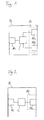
- FIG 1 shows an embodiment of an inventive Access points B.
- Access point B hereinafter also the base station called, has a device according to the invention 10 for sending and receiving radio signals.
- the device 10 Around in particular to be able to offer two complementary services, the device 10 has two equal sub-units 10a, 10b, each with an air interface for sending and receiving radio signals. Any of these Sub-units 10a, 10b work according to a special Radio standard S, D, each adapted to one of the services is and has a compliant with the respective radio standard S, D. Transmitting and receiving device (not shown here).
- the first subunit 10a is preferably for transmission of voice and video signals.
- the one for this the proposed radio standards e.g. DECT or Bluetooth
- high availability Quality of Service
- a relatively small bandwidth Because of its wide Distribution is suitable for the transmission of voice and video signals in particular the ETSI (European Telecommunication Standards Institute) - Standard DECT (Digital European Cordless Telephone).
- the second subunit 10b is preferably for the Transmission of data signals provided.
- the radio standards in question for this are broadband standards in particular that are not Offer quality of service.
- One of these for data transmission Optimized radio standards is also available as a wireless LAN designated IEEE802.11b standard.
- this radio standard in the base station according to the invention speaks in particular that the IEEE802.11b standard already used many times and his Technology has therefore already been sufficiently tested.
- both radio standards S, D DECT and IEEE802.11b operate on different license-free frequency bands (1.8 GHz and 2.4 GHz). Therefore, it is mutual Influencing of the two subunits 10a and 10b sent or received signals minimal.
- DECT and IEEE802.11b e.g. also a combination of IEEE802.11a for data transmission at 54 MB / s in the 5 GHz band with Bluetooth for voice transmission possible in the 2.4 GHz band.
- other data transmission standards such as. the derivatives of IEEE802.11x are each with a standard that is suitable for voice transmission can be combined.
- the base station B has a wired Interface 15 on.
- This interface 15 is preferred designed as an Ethernet interface and thus allows in particular an integration of base station B into an existing one Network infrastructure (intranet and internet).
- alternative can also be connected via a DSL interface or via a special interface for connecting to another done as an ethernet network.
- the Internet protocol is preferred IP used.
- IP Data protocols can be used. Because of their currently strong The most widespread are the TCP and the UTP data protocol provided.
- IEEE802.11b Because of its compatibility with Ethernet or DSL, it is suitable the IEEE802.11b standard also used for data transmission on the wired side of the base station B. Therefore with data forwarding from the air interface 10b to the Ethernet or DSL interface 15 no complex implementation of the data packets necessary.
- the voice and video signals of the subunit 10b for transmission over the physical network NET preferably with the help of a converter unit 20 of the DECT standard implemented on a Voice over IP standard.
- a converter unit 20 is provided, in which a special Standard (H.323 or SIP) is implemented.
- the can Converter unit 20 either in the base station B itself or trained anywhere in the IP network his.
- the base station B shown in Figure 1 has no internal Converter unit 20 on.
- the DECT protocol elements of the second subunit 10b must therefore be wired Interface 15 packed in IP packets and over an IP connection V sent to an external converter unit 20 (tunneled) become.
- Base unit B is a control unit C, which in the exemplary embodiment is centrally formed and via separate connecting lines with each of the three interfaces 10a, 10b, 15 is connected.
- FIG. 2 shows a further embodiment of an inventive Base station B.
- Base station B for connection to a physical network NET a wired Interface 15, which is preferably analogous to the wired interface 15 shown in FIG. 1 is trained.
- Control unit C trained.
- the base station points to the establishment of wireless connections B a device 10 for sending and receiving signals on, in which a radio standard S for transmission of voice and Video signals and a radio standard D for the transmission of data is implemented.
- a device 10 for sending and receiving signals on in which a radio standard S for transmission of voice and Video signals and a radio standard D for the transmission of data is implemented.
- the Device 10 a single sub-unit 10c, in which both radio standards S, D are integrated.
- the sub-unit 10c is therefore only a single connection between the central control unit C and the device 10 necessary.
- FIG 3 shows a third embodiment of an inventive Base station, the structure of which is essentially the same corresponds to the structure shown in Figure 1, but for the simplified Control the two air interface units 10a, 10b each have a separate control unit C1, C2, the respective air interface with the network interface 15 connect.
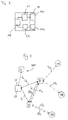
- FIG. 4 shows an inventive radio system consisting of two base stations B, B 'and three mobile terminals M1, M2, M3, which are connected to one another via wireless transmission links VS 1 , VS 2 , VS 3 , VD 1 , VD 2 , VD 3 .
- Each of the two base stations B, B ' has, as shown in FIG. 1 or 2, a device 10 for wireless signal transmission according to a first and a second radio standard S, D in order to transmit or receive voice or video signals and data simultaneously to be able to.
- the radio connections VS 1 , VS 2 , VS 3 , VD 1 , VD 2 , VD 3 between the base stations B, B 'and the mobile terminals M1, M2, M3 are shown as broken lines.
- a dashed line represents a radio connection according to a radio standard S (DECT) optimized for voice and video transmission
- a dash-dotted line represents a radio connection that uses a radio standard D (IEEE802.11b) intended for data transmission.
- a bidirectional transmission path is indicated by arrows marked at both ends of the respective lines.
- the first base station B exchanges voice or video signals with the first mobile terminal M1 via a first wireless connection VS 1 and data with the second mobile terminal M2 via a second connection VD 1 .
- the second base station B ' communicates with the third mobile emitter device M3 via two separate wireless connections VS 2 VD 2 .
- voice or video signals are simultaneously exchanged between the base station B 'and the third mobile terminal M3 via the third wireless connection link VS 2 and data via the fourth wireless connection link VD 2 .
- two further wireless connection links VS 3 VD 3 are formed between the two base stations B, B '.
- These two connection lines VS 3 VD 3 which are preferably of optional design, serve the two base stations B, B 'for communication, in particular if there is no hard-wired connection between the two base stations B, B'.
- each of the two base stations B, B' preferably has an Ethernet interface 15.
- a central control unit 2 which carries out mobility monitoring and control (roaming and handover) of the mobile terminals M1, M2, M3.
- the central control unit ST also carries out user and device authentication of the mobile terminals M1, M2, M3.
- a converter unit 20 is implemented within the control unit ST.
- the converter unit 20 is used to convert voice and video signals from the DECT to a Voice over IP standard.
- the network component N can represent, for example, an access component (gateway) to an external network.
- a connection to a public or private telecommunications network can also be established via the network component N.
- the base stations B, B 'shown in FIG. 4 form a simple one Radio network, in the coverage area of the mobile devices M1, M2, M3 of the two base stations B, B ' implemented voice and data service are available.
- the radio system is also heterogeneous Has base stations in which other radio standards are implemented as the two in the two base stations B, B 'combined radio standards.
Landscapes
- Engineering & Computer Science (AREA)
- Computer Networks & Wireless Communication (AREA)
- Signal Processing (AREA)
- Mobile Radio Communication Systems (AREA)
- Small-Scale Networks (AREA)
- Radio Relay Systems (AREA)
- Reduction Or Emphasis Of Bandwidth Of Signals (AREA)
Abstract
Description
- B
- Basisstation
- M
- drahtloses Endgerät
- S
- Standard zur Sprachübertragung
- D
- Standard zur Datenübertragung
- ST
- Steuereinheit
- C
- Kontrolleinheit der Basisstation
- NET
- physikalisches Netzwerk
- N
- Netzwekkomponente
- V
- Netzwerkverbindung
- VS
- drahtlose Verbindung zur Sprachübertragung
- VD
- drahtlose Verbindung zur Datenübertragung
- 10
- Einrichtung zum Senden und Empfangen von Signalen
- 15
- drahtgebundene Schnittstelle der Basisstation
- 20
- Umsetzereinheit
Claims (14)
- Basisstation für ein Funksystem, mit einer Einrichtung (10) zum Senden und Empfangen von Signalen nach einem ersten und einem zweiten Funkstandard (S, D), wobei der erste Funkstandard (S) für Sprachübertragung und der zweite Funkstandard (D) für Datenübertragung optimiert ist,
dadurch gekennzeichnet, dass der zweite Funkstandard (D) ein IEEE802.11x-Derivat ist. - Basisstation nach Anspruch 1,
dadurch gekennzeichnet,
der erste Funkstandard (S) ein DECT-Standard, ein dem DECT verwandter Standard oder ein Bluetooth-Standard ist. - Basisstation nach Anspruch 2,
dadurch gekennzeichnet, dass der erste Funkstandard (S) ein DECT-Standard oder ein dem DECT verwandter Standard ist, und
dass der zweite Funkstandard (D) ein IEEE802.11b-Standard ist. - Basisstation nach Anspruch 2,
dadurch gekennzeichnet, dass der erste Funkstandard (S) ein Bluetooth-Standard ist und der zweite Funkstandard (D) ein IEEE802.11a-Standard ist. - Basisstation nach Anspruch 1,
dadurch gekennzeichnet, dass der erste Funkstandard (S) ein IEEE802.11e-Standard ist. - Basisstation nach einem der Ansprüche 1 bis 5,
dadurch gekennzeichnet, dass die Basisstation (B, B') eine Schnittstelle (15) zum Anbinden an ein physikalisches Netzwerk (NET) aufweist. - Basisstation nach Anspruch 6,
dadurch gekennzeichnet, dass die Schnittstelle (15) eine Ethernet- oder eine DSL-Schnittstelle ist. - Basisstation nach Anspruch 6 oder 7,
dadurch gekennzeichnet, dass als Protokoll für eine Datenübertragung über die Schnittstelle (15) ein IP-Protokoll vorgesehen ist. - Basisstation nach einem der Ansprüche 6 bis 8,
dadurch gekennzeichnet, dass als Datenprotokoll für die über die Schnittstelle (15) übertragenen Daten TCP oder UDP vorgesehen ist. - Funksystem mit mindestens einer Basisstation (B, B') nach einem der Ansprüche 1 bis 9 und mindestens einem mobilen Endgerät (M1, M2, M3),
dadurch gekennzeichnet, dass eine Steuereinheit (ST) vorgesehen ist, um die Kommunikation zwischen der Basisstation (B, B') und dem mobilen Endgerät (M1, M2, M3) zu steuern. - Funksystem nach Anspruch 10,
dadurch gekennzeichnet, dass die Steuereinheit (ST) eine für Benutzer- und Geräteauthentifizierung ausgelegt ist. - Funksystem nach Anspruch 10 oder 11,
dadurch gekennzeichnet, dass eine Umsetzereinheit (20) vorgesehen ist, um Signalisierungen und Sprach- und Videosignale von dem Funkstandard zur Sprachübertragung (S) auf einen Voice-over-IP-Standard umzusetzen. - Funksystem nach einem der Ansprüche 10 bis 12,
dadurch gekennzeichnet, dass die Umsetzereinheit (20) als eine H.323- oder SIP-Umsetzereinheit ausgebildet ist. - Funksystem nach einem der Ansprüche 10 bis 13,
dadurch gekennzeichnet, dass das das Funksystem an ein öffentliches oder privates Telekommunikationsnetz angeschlossen ist.
Applications Claiming Priority (2)
| Application Number | Priority Date | Filing Date | Title |
|---|---|---|---|
| DE10202141A DE10202141A1 (de) | 2002-01-21 | 2002-01-21 | Accesspoint mit kombinierten Funkstandards |
| DE10202141 | 2002-01-21 |
Publications (3)
| Publication Number | Publication Date |
|---|---|
| EP1330076A2 true EP1330076A2 (de) | 2003-07-23 |
| EP1330076A3 EP1330076A3 (de) | 2004-01-07 |
| EP1330076B1 EP1330076B1 (de) | 2006-07-19 |
Family
ID=7712674
Family Applications (1)
| Application Number | Title | Priority Date | Filing Date |
|---|---|---|---|
| EP03001123A Expired - Lifetime EP1330076B1 (de) | 2002-01-21 | 2003-01-20 | Accesspoint mit kombinierten Funkstandards |
Country Status (3)
| Country | Link |
|---|---|
| EP (1) | EP1330076B1 (de) |
| AT (1) | ATE333737T1 (de) |
| DE (2) | DE10202141A1 (de) |
Cited By (5)
| Publication number | Priority date | Publication date | Assignee | Title |
|---|---|---|---|---|
| WO2005029713A3 (de) * | 2003-09-24 | 2005-05-26 | Siemens Ag | Vorrichtung für eine funkstation für mehrere unterschiedliche funkstandards |
| WO2005064964A1 (en) * | 2003-12-23 | 2005-07-14 | Plantronics, Inc. | Integrated network system comprising a gateway with two wireless interfaces |
| EP1675423A1 (de) * | 2004-12-24 | 2006-06-28 | Mitsubishi Electric Information Technology Centre Europe B.V. | verfahren für das Übertragen der Informationen, die erhöhte Verteilung der spektralen Ressourcen mit einbeziehen |
| EP2315376A1 (de) * | 2009-10-23 | 2011-04-27 | Alcatel Lucent | System und Verfahren für ein Fernabschalten einer Funkkommunikationsverbindung |
| CN102857609A (zh) * | 2011-06-27 | 2013-01-02 | Gn奈康有限公司 | 在耳机与基站之间传输无线电信号 |
Family Cites Families (10)
| Publication number | Priority date | Publication date | Assignee | Title |
|---|---|---|---|---|
| US5600633A (en) * | 1995-02-24 | 1997-02-04 | Lucent Technologies Inc. | Wireless telecommunication base station for integrated wireless services with ATM processing |
| DE19945663A1 (de) * | 1999-09-23 | 2001-04-05 | Siemens Ag | Internet-Telefonadapter |
| EP1096818A1 (de) * | 1999-10-29 | 2001-05-02 | TELEFONAKTIEBOLAGET LM ERICSSON (publ) | Basisstation mit einer ersten und zweiten Basiseinheit |
| WO2001050624A1 (en) * | 1999-12-30 | 2001-07-12 | Morphics Technology, Inc. | Method and apparatus to support multi standard, multi service base-stations for wireless voice and data networks |
| DE60030086T2 (de) * | 2000-01-20 | 2007-01-04 | Lucent Technologies Inc. | Interoperabilität von Bluetooth und IEEE 802.11 |
| EP1158754A3 (de) * | 2000-01-27 | 2003-11-12 | Phillip Jarrett | Schnurloses Mehrzweck-Mobilfernsprechsystem |
| AU2001234691A1 (en) * | 2000-01-31 | 2001-08-07 | Aeptec Microsystems, Inc. | Broadband communications access device |
| DE10016622B4 (de) * | 2000-04-04 | 2006-10-19 | Siemens Ag | Verfahren zum Steuern von Leistungsmerkmalen in einem Funknetz und Anordnungen zur Realisierung des Verfahrens |
| AU2001244951A1 (en) * | 2000-04-05 | 2001-10-15 | Telefonaktiebolaget Lm Ericsson (Publ) | Telecommunications network integrating cellular, packet-switched, and voice-over-ip infrastructures |
| US7680085B2 (en) * | 2001-07-24 | 2010-03-16 | Symbol Technologies, Inc. | Out-of-band management and traffic monitoring for wireless access points |
-
2002
- 2002-01-21 DE DE10202141A patent/DE10202141A1/de not_active Withdrawn
-
2003
- 2003-01-20 DE DE50304261T patent/DE50304261D1/de not_active Expired - Lifetime
- 2003-01-20 AT AT03001123T patent/ATE333737T1/de not_active IP Right Cessation
- 2003-01-20 EP EP03001123A patent/EP1330076B1/de not_active Expired - Lifetime
Cited By (9)
| Publication number | Priority date | Publication date | Assignee | Title |
|---|---|---|---|---|
| WO2005029713A3 (de) * | 2003-09-24 | 2005-05-26 | Siemens Ag | Vorrichtung für eine funkstation für mehrere unterschiedliche funkstandards |
| WO2005064964A1 (en) * | 2003-12-23 | 2005-07-14 | Plantronics, Inc. | Integrated network system comprising a gateway with two wireless interfaces |
| US7486965B1 (en) | 2003-12-23 | 2009-02-03 | Plantronics, Inc. | Integrated network system |
| EP1675423A1 (de) * | 2004-12-24 | 2006-06-28 | Mitsubishi Electric Information Technology Centre Europe B.V. | verfahren für das Übertragen der Informationen, die erhöhte Verteilung der spektralen Ressourcen mit einbeziehen |
| EP2136596A1 (de) * | 2004-12-24 | 2009-12-23 | Mitsubishi Electric R&D Centre Europe B.V. | Verfahren zur Übertragung von Information mit verbesserter Zuweisung von spektralen Ressourcen |
| US8027392B2 (en) | 2004-12-24 | 2011-09-27 | Mitsubishi Denki Kabushiki Kaisha | Method for transmitting information involving enhanced allocation of spectral resources |
| EP2315376A1 (de) * | 2009-10-23 | 2011-04-27 | Alcatel Lucent | System und Verfahren für ein Fernabschalten einer Funkkommunikationsverbindung |
| CN102857609A (zh) * | 2011-06-27 | 2013-01-02 | Gn奈康有限公司 | 在耳机与基站之间传输无线电信号 |
| CN102857609B (zh) * | 2011-06-27 | 2015-08-26 | Gn奈康有限公司 | 在耳机与基站之间传输无线电信号 |
Also Published As
| Publication number | Publication date |
|---|---|
| ATE333737T1 (de) | 2006-08-15 |
| EP1330076A3 (de) | 2004-01-07 |
| DE10202141A1 (de) | 2003-07-31 |
| DE50304261D1 (de) | 2006-08-31 |
| EP1330076B1 (de) | 2006-07-19 |
Similar Documents
| Publication | Publication Date | Title |
|---|---|---|
| DE10034686A1 (de) | Anordnung zur Informationsübermittlung zwischen zwei Kommunikationseinrichtungen | |
| EP0935895B1 (de) | Verfahren und telekommunikationsschnittstelle zum übertragen kontinuierlicher und/oder diskontinuierlicher datenströme in einem hybriden telekommunikationssystem, insbesondere einem "isdn - dect-spezifischen rll/wll"-system | |
| DE3843565A1 (de) | Funktelefonsystem in form einer nebenstellenanlage | |
| EP0952749A2 (de) | Dezentral gesteuertes Handover mobiler Endeinrichtungen | |
| WO2005004432A1 (de) | Verfahren zur steuerung von datenverbindungen | |
| WO1999057848A2 (de) | Verfahren zum übertragen von nutzdaten in telekommunikationssystemen | |
| EP1330076B1 (de) | Accesspoint mit kombinierten Funkstandards | |
| DE19640220A1 (de) | Schnurloskommunikationsanlage gemäß dem ETSI-Standard DECT | |
| DE10142007C1 (de) | Anordnung zur drahtlosen Anbindung von Endeinrichtungen an ein Kommunikationssystem | |
| DE19834634A1 (de) | Kommunikationsanordnung mit zumindest einer zentralen Kommunikationseinrichtung, an die drahtlose Netzabschlußeinrichtungen für den Anschluß von Kommunikationsendgeräten anschließbar sind | |
| EP1236311B1 (de) | Verfahren zur steuerung von funkstationen | |
| DE102004023803B4 (de) | Kommunikationsendgerät | |
| DE69532075T2 (de) | Zwischenverstärker-anordnung in einem funkkommunikationssystem | |
| DE10220919B4 (de) | Verfahren zum Betrieb eines Bluetooth-Handsets an Basisstationen | |
| DE19735384A1 (de) | Verfahren, System und Vorrichtungen zur Funkanbindung mehrerer Endgeräte über eine Basisstation an eine Schnittstelle eines Telefon- oder Datennetzes | |
| DE19639608C2 (de) | Verfahren zur Verbindungssteuerung von drahtlos an Kommunikationsnetze angeschlossenen Kommunikationsendgeräten | |
| EP1085735B1 (de) | Anordnung zur Informationsübermittlung zwischen zwei Kommunikationseinrichtungen | |
| EP1668813B1 (de) | Verfahren zum verbessern der qualität einer sprachübertragung über eine luftschnittstelle | |
| DE102008048871A1 (de) | Verfahren und Vorrichtung zur Vermittlung von Daten in einem TETRA Netz | |
| EP1811738B1 (de) | WLAN-Basisstation, lokale Kommunikationsanlage und Verfahren zum Herstellen einer Sprachverbindung | |
| DE19635327C1 (de) | Verfahren zum Belegen von Zeitschlitzen in drahtlosen Kommunikationsnetzen | |
| DE102005027959A1 (de) | Verfahren und Vorrichtung zur Datenübertragung | |
| WO1998014028A1 (de) | Mobiles kommunikationsendgerät mit telefonfunktion und einem isdn-basisanschluss | |
| WO2005096595A1 (de) | Technisches übertragungssystem | |
| DE102005001258A1 (de) | Schaltungsanordnung und Verfahren zur Datenübertragung |
Legal Events
| Date | Code | Title | Description |
|---|---|---|---|
| PUAI | Public reference made under article 153(3) epc to a published international application that has entered the european phase |
Free format text: ORIGINAL CODE: 0009012 |
|
| AK | Designated contracting states |
Designated state(s): AT BE BG CH CY CZ DE DK EE ES FI FR GB GR HU IE IT LI LU MC NL PT SE SI SK TR |
|
| AX | Request for extension of the european patent |
Extension state: AL LT LV MK RO |
|
| PUAL | Search report despatched |
Free format text: ORIGINAL CODE: 0009013 |
|
| AK | Designated contracting states |
Kind code of ref document: A3 Designated state(s): AT BE BG CH CY CZ DE DK EE ES FI FR GB GR HU IE IT LI LU MC NL PT SE SI SK TR |
|
| AX | Request for extension of the european patent |
Extension state: AL LT LV MK RO |
|
| 17P | Request for examination filed |
Effective date: 20040707 |
|
| AKX | Designation fees paid |
Designated state(s): AT BE BG CH CY CZ DE DK EE ES FI FR GB GR HU IE IT LI LU MC NL PT SE SI SK TR |
|
| 17Q | First examination report despatched |
Effective date: 20040906 |
|
| GRAP | Despatch of communication of intention to grant a patent |
Free format text: ORIGINAL CODE: EPIDOSNIGR1 |
|
| GRAS | Grant fee paid |
Free format text: ORIGINAL CODE: EPIDOSNIGR3 |
|
| GRAA | (expected) grant |
Free format text: ORIGINAL CODE: 0009210 |
|
| AK | Designated contracting states |
Kind code of ref document: B1 Designated state(s): AT BE BG CH CY CZ DE DK EE ES FI FR GB GR HU IE IT LI LU MC NL PT SE SI SK TR |
|
| PG25 | Lapsed in a contracting state [announced via postgrant information from national office to epo] |
Ref country code: CZ Free format text: LAPSE BECAUSE OF FAILURE TO SUBMIT A TRANSLATION OF THE DESCRIPTION OR TO PAY THE FEE WITHIN THE PRESCRIBED TIME-LIMIT Effective date: 20060719 Ref country code: FI Free format text: LAPSE BECAUSE OF FAILURE TO SUBMIT A TRANSLATION OF THE DESCRIPTION OR TO PAY THE FEE WITHIN THE PRESCRIBED TIME-LIMIT Effective date: 20060719 Ref country code: IT Free format text: LAPSE BECAUSE OF FAILURE TO SUBMIT A TRANSLATION OF THE DESCRIPTION OR TO PAY THE FEE WITHIN THE PRESCRIBED TIME-LIMIT;WARNING: LAPSES OF ITALIAN PATENTS WITH EFFECTIVE DATE BEFORE 2007 MAY HAVE OCCURRED AT ANY TIME BEFORE 2007. THE CORRECT EFFECTIVE DATE MAY BE DIFFERENT FROM THE ONE RECORDED. Effective date: 20060719 Ref country code: SI Free format text: LAPSE BECAUSE OF FAILURE TO SUBMIT A TRANSLATION OF THE DESCRIPTION OR TO PAY THE FEE WITHIN THE PRESCRIBED TIME-LIMIT Effective date: 20060719 Ref country code: IE Free format text: LAPSE BECAUSE OF FAILURE TO SUBMIT A TRANSLATION OF THE DESCRIPTION OR TO PAY THE FEE WITHIN THE PRESCRIBED TIME-LIMIT Effective date: 20060719 Ref country code: SK Free format text: LAPSE BECAUSE OF FAILURE TO SUBMIT A TRANSLATION OF THE DESCRIPTION OR TO PAY THE FEE WITHIN THE PRESCRIBED TIME-LIMIT Effective date: 20060719 Ref country code: NL Free format text: LAPSE BECAUSE OF FAILURE TO SUBMIT A TRANSLATION OF THE DESCRIPTION OR TO PAY THE FEE WITHIN THE PRESCRIBED TIME-LIMIT Effective date: 20060719 |
|
| REG | Reference to a national code |
Ref country code: GB Ref legal event code: FG4D Free format text: NOT ENGLISH |
|
| REG | Reference to a national code |
Ref country code: CH Ref legal event code: EP |
|
| REG | Reference to a national code |
Ref country code: IE Ref legal event code: FG4D Free format text: LANGUAGE OF EP DOCUMENT: GERMAN |
|
| REF | Corresponds to: |
Ref document number: 50304261 Country of ref document: DE Date of ref document: 20060831 Kind code of ref document: P |
|
| PG25 | Lapsed in a contracting state [announced via postgrant information from national office to epo] |
Ref country code: DK Free format text: LAPSE BECAUSE OF FAILURE TO SUBMIT A TRANSLATION OF THE DESCRIPTION OR TO PAY THE FEE WITHIN THE PRESCRIBED TIME-LIMIT Effective date: 20061019 Ref country code: SE Free format text: LAPSE BECAUSE OF FAILURE TO SUBMIT A TRANSLATION OF THE DESCRIPTION OR TO PAY THE FEE WITHIN THE PRESCRIBED TIME-LIMIT Effective date: 20061019 Ref country code: BG Free format text: LAPSE BECAUSE OF FAILURE TO SUBMIT A TRANSLATION OF THE DESCRIPTION OR TO PAY THE FEE WITHIN THE PRESCRIBED TIME-LIMIT Effective date: 20061019 |
|
| PG25 | Lapsed in a contracting state [announced via postgrant information from national office to epo] |
Ref country code: ES Free format text: LAPSE BECAUSE OF FAILURE TO SUBMIT A TRANSLATION OF THE DESCRIPTION OR TO PAY THE FEE WITHIN THE PRESCRIBED TIME-LIMIT Effective date: 20061030 |
|
| GBT | Gb: translation of ep patent filed (gb section 77(6)(a)/1977) |
Effective date: 20061023 |
|
| PG25 | Lapsed in a contracting state [announced via postgrant information from national office to epo] |
Ref country code: PT Free format text: LAPSE BECAUSE OF FAILURE TO SUBMIT A TRANSLATION OF THE DESCRIPTION OR TO PAY THE FEE WITHIN THE PRESCRIBED TIME-LIMIT Effective date: 20061219 |
|
| NLV1 | Nl: lapsed or annulled due to failure to fulfill the requirements of art. 29p and 29m of the patents act | ||
| PG25 | Lapsed in a contracting state [announced via postgrant information from national office to epo] |
Ref country code: LI Free format text: LAPSE BECAUSE OF NON-PAYMENT OF DUE FEES Effective date: 20070131 Ref country code: CH Free format text: LAPSE BECAUSE OF NON-PAYMENT OF DUE FEES Effective date: 20070131 Ref country code: MC Free format text: LAPSE BECAUSE OF NON-PAYMENT OF DUE FEES Effective date: 20070131 |
|
| REG | Reference to a national code |
Ref country code: IE Ref legal event code: FD4D |
|
| ET | Fr: translation filed | ||
| PLBE | No opposition filed within time limit |
Free format text: ORIGINAL CODE: 0009261 |
|
| STAA | Information on the status of an ep patent application or granted ep patent |
Free format text: STATUS: NO OPPOSITION FILED WITHIN TIME LIMIT |
|
| 26N | No opposition filed |
Effective date: 20070420 |
|
| REG | Reference to a national code |
Ref country code: CH Ref legal event code: PL |
|
| BERE | Be: lapsed |
Owner name: TENOVIS G.M.B.H. & CO. KG Effective date: 20070131 |
|
| PG25 | Lapsed in a contracting state [announced via postgrant information from national office to epo] |
Ref country code: BE Free format text: LAPSE BECAUSE OF NON-PAYMENT OF DUE FEES Effective date: 20070131 |
|
| PG25 | Lapsed in a contracting state [announced via postgrant information from national office to epo] |
Ref country code: GR Free format text: LAPSE BECAUSE OF FAILURE TO SUBMIT A TRANSLATION OF THE DESCRIPTION OR TO PAY THE FEE WITHIN THE PRESCRIBED TIME-LIMIT Effective date: 20061020 |
|
| PG25 | Lapsed in a contracting state [announced via postgrant information from national office to epo] |
Ref country code: AT Free format text: LAPSE BECAUSE OF NON-PAYMENT OF DUE FEES Effective date: 20070120 |
|
| PG25 | Lapsed in a contracting state [announced via postgrant information from national office to epo] |
Ref country code: EE Free format text: LAPSE BECAUSE OF FAILURE TO SUBMIT A TRANSLATION OF THE DESCRIPTION OR TO PAY THE FEE WITHIN THE PRESCRIBED TIME-LIMIT Effective date: 20060719 |
|
| PG25 | Lapsed in a contracting state [announced via postgrant information from national office to epo] |
Ref country code: LU Free format text: LAPSE BECAUSE OF NON-PAYMENT OF DUE FEES Effective date: 20070120 Ref country code: CY Free format text: LAPSE BECAUSE OF FAILURE TO SUBMIT A TRANSLATION OF THE DESCRIPTION OR TO PAY THE FEE WITHIN THE PRESCRIBED TIME-LIMIT Effective date: 20060719 |
|
| PG25 | Lapsed in a contracting state [announced via postgrant information from national office to epo] |
Ref country code: HU Free format text: LAPSE BECAUSE OF FAILURE TO SUBMIT A TRANSLATION OF THE DESCRIPTION OR TO PAY THE FEE WITHIN THE PRESCRIBED TIME-LIMIT Effective date: 20070120 Ref country code: TR Free format text: LAPSE BECAUSE OF FAILURE TO SUBMIT A TRANSLATION OF THE DESCRIPTION OR TO PAY THE FEE WITHIN THE PRESCRIBED TIME-LIMIT Effective date: 20060719 |
|
| PGFP | Annual fee paid to national office [announced via postgrant information from national office to epo] |
Ref country code: DE Payment date: 20140128 Year of fee payment: 12 |
|
| PGFP | Annual fee paid to national office [announced via postgrant information from national office to epo] |
Ref country code: FR Payment date: 20140124 Year of fee payment: 12 |
|
| PGFP | Annual fee paid to national office [announced via postgrant information from national office to epo] |
Ref country code: GB Payment date: 20140123 Year of fee payment: 12 |
|
| REG | Reference to a national code |
Ref country code: DE Ref legal event code: R119 Ref document number: 50304261 Country of ref document: DE |
|
| GBPC | Gb: european patent ceased through non-payment of renewal fee |
Effective date: 20150120 |
|
| PG25 | Lapsed in a contracting state [announced via postgrant information from national office to epo] |
Ref country code: GB Free format text: LAPSE BECAUSE OF NON-PAYMENT OF DUE FEES Effective date: 20150120 Ref country code: DE Free format text: LAPSE BECAUSE OF NON-PAYMENT OF DUE FEES Effective date: 20150801 |
|
| REG | Reference to a national code |
Ref country code: FR Ref legal event code: ST Effective date: 20150930 |
|
| PG25 | Lapsed in a contracting state [announced via postgrant information from national office to epo] |
Ref country code: FR Free format text: LAPSE BECAUSE OF NON-PAYMENT OF DUE FEES Effective date: 20150202 |