EP1330806B1 - Verfahren zur führung eines flugzeugs in einer formation - Google Patents
Verfahren zur führung eines flugzeugs in einer formation Download PDFInfo
- Publication number
- EP1330806B1 EP1330806B1 EP01980611A EP01980611A EP1330806B1 EP 1330806 B1 EP1330806 B1 EP 1330806B1 EP 01980611 A EP01980611 A EP 01980611A EP 01980611 A EP01980611 A EP 01980611A EP 1330806 B1 EP1330806 B1 EP 1330806B1
- Authority
- EP
- European Patent Office
- Prior art keywords
- aircraft
- slave
- process according
- master
- distance
- Prior art date
- Legal status (The legal status is an assumption and is not a legal conclusion. Google has not performed a legal analysis and makes no representation as to the accuracy of the status listed.)
- Expired - Lifetime
Links
- 238000000034 method Methods 0.000 title claims description 54
- 238000000926 separation method Methods 0.000 claims description 63
- 230000008569 process Effects 0.000 claims description 24
- 238000012937 correction Methods 0.000 claims description 18
- 238000001514 detection method Methods 0.000 claims description 3
- 238000002360 preparation method Methods 0.000 claims description 3
- 230000001419 dependent effect Effects 0.000 claims description 2
- 238000012544 monitoring process Methods 0.000 description 7
- 230000000007 visual effect Effects 0.000 description 6
- 229930186657 Lat Natural products 0.000 description 4
- 230000008859 change Effects 0.000 description 4
- 238000004891 communication Methods 0.000 description 4
- 230000006870 function Effects 0.000 description 4
- 238000005259 measurement Methods 0.000 description 4
- 238000013459 approach Methods 0.000 description 3
- 238000000265 homogenisation Methods 0.000 description 3
- 230000003068 static effect Effects 0.000 description 3
- 239000013598 vector Substances 0.000 description 3
- 230000008901 benefit Effects 0.000 description 2
- 238000012423 maintenance Methods 0.000 description 2
- 230000008520 organization Effects 0.000 description 2
- 230000000737 periodic effect Effects 0.000 description 2
- 230000001105 regulatory effect Effects 0.000 description 2
- 238000012360 testing method Methods 0.000 description 2
- 101100182247 Caenorhabditis elegans lat-1 gene Proteins 0.000 description 1
- 241001644893 Entandrophragma utile Species 0.000 description 1
- 230000001133 acceleration Effects 0.000 description 1
- 230000009471 action Effects 0.000 description 1
- 230000005540 biological transmission Effects 0.000 description 1
- 238000011161 development Methods 0.000 description 1
- 230000010006 flight Effects 0.000 description 1
- 238000003780 insertion Methods 0.000 description 1
- 230000037431 insertion Effects 0.000 description 1
- 238000012986 modification Methods 0.000 description 1
- 230000004048 modification Effects 0.000 description 1
- 230000009467 reduction Effects 0.000 description 1
Images

Classifications
-
- G—PHYSICS
- G08—SIGNALLING
- G08G—TRAFFIC CONTROL SYSTEMS
- G08G5/00—Traffic control systems for aircraft
- G08G5/20—Arrangements for acquiring, generating, sharing or displaying traffic information
- G08G5/25—Transmission of traffic-related information between aircraft
-
- G—PHYSICS
- G05—CONTROLLING; REGULATING
- G05D—SYSTEMS FOR CONTROLLING OR REGULATING NON-ELECTRIC VARIABLES
- G05D1/00—Control of position, course, altitude or attitude of land, water, air or space vehicles, e.g. using automatic pilots
- G05D1/10—Simultaneous control of position or course in three dimensions
- G05D1/101—Simultaneous control of position or course in three dimensions specially adapted for aircraft
- G05D1/104—Simultaneous control of position or course in three dimensions specially adapted for aircraft involving a plurality of aircrafts, e.g. formation flying
-
- G—PHYSICS
- G08—SIGNALLING
- G08G—TRAFFIC CONTROL SYSTEMS
- G08G5/00—Traffic control systems for aircraft
- G08G5/50—Navigation or guidance aids
- G08G5/53—Navigation or guidance aids for cruising
-
- G—PHYSICS
- G08—SIGNALLING
- G08G—TRAFFIC CONTROL SYSTEMS
- G08G5/00—Traffic control systems for aircraft
- G08G5/50—Navigation or guidance aids
- G08G5/55—Navigation or guidance aids for a single aircraft
Definitions
- the present invention relates to the guidance of an aircraft to enable it, once inserted into the traffic of an air corridor, to maintain a minimum separation distance with the aircraft which precedes it to prevent any risk of collision.
- the visual flight technique is coupled with the routing of aircraft from the ground, by air traffic controllers which affect aircraft positions and speeds allowing them to fit into the traffic of an air corridor respecting minimum separation distances between aircraft eliminating the risk of collision.
- air traffic controllers which affect aircraft positions and speeds allowing them to fit into the traffic of an air corridor respecting minimum separation distances between aircraft eliminating the risk of collision.
- the safety of the visual flight technique depends on the visibility conditions so that, in order to maintain the same level of safety, a minimum separation 'as much as the visibility conditions are bad.
- ADS-B an acronym derived from the Anglo-Saxon "Automatic Dependent Surveillance Broadcast", by which an aircraft informs other aircraft operating in the vicinity and Earth stations within range, position and velocity vector, either periodically or on interrogation.
- An aircraft operating in the middle of a traffic of other aircraft equipped with the ADS-B system is able to know its situation compared to other aircraft and to foresee, in the short term, the evolution of this situation and therefore the risks of collision in the short and medium term, if no correction is made to the trajectories of the aircraft considered. With this knowledge, he is able to change his trajectory or ask another aircraft to change its trajectory to eliminate the risk of collision.
- US Pat. No. 4,674,710 describes an example of a method for automatically maintaining the distances between the team members and the leader of a squadron during a turn.
- the knowledge, at the level of each crew member, of the distance, the heading and the air speed of the leader is used to make estimate by a teammate of the target distances to be respected with respect to the leader, at the same time in longitudinal and lateral.
- Each team member then deduces the air speed to adopt from that of the leader and the evolution of his placement errors with respect to the set distances to be respected.
- Such a method which seeks, permanently, the respect of set distances in lateral and longitudinal compared to a leader has the advantage of allowing to better maintain the aircraft of the crew members in the center of their envelope of flight.
- it imposes frequent acceleration changes that affect the comfort of passengers and that it is not very suitable for maintaining a safe distance between passenger aircraft following the same portion of road.
- the present invention aims to automatically maintain the safety distances between aircraft in the same portion of road with a minimum of changes in air speed for greater passenger comfort.
- This additional support provided to the aircraft crew and to any intervening air control authority may reduce spacing between aircraft for the same level of safety and thus increase traffic in an air corridor.
- the subject of the invention is a method of guiding a so-called slave aircraft in the context of a convoy flight, behind another so-called master aircraft, on the same predetermined trajectory and with a minimum separation distance of setpoint D SEP , consisting in giving to the speed calculated with respect to the air V CAS, S of the slave aircraft, that is to say calculated from the measurements of temperature and static and dynamic pressures and known under the name of "Calculated Air Speed", an initial value V CAS0, S , periodically to be deduced, the distance separating the slave aircraft from the master aircraft from the geographical position of the slave aircraft and from that of the aircraft master in the same moment and the known form of the trajectory followed by the master and slave aircraft, then periodically correct the calculated speed with respect to the air V CAS, S of the slave aircraft by modifying it with a corrective term E from the eca rt found between the measured separation distance D M and the minimum distance D SEP reference separation according to a recurrence relation of the form: ⁇ V VS AT S , S (
- the initial value of the calculated speed relative to the air of the slave aircraft is taken equal to the calculated speed relative to the air provided during the preparation of the flight plan of the slave aircraft 2, to where it is at the time of implementation of the guiding method, this speed calculated with respect to the air resulting from the application of a definition law 4D, that is to say function of four variables: altitude, time, latitude and longitude, this case being adapted to a situation where the aircraft is descending, for example when approaching an airstrip.
- a definition law 4D that is to say function of four variables: altitude, time, latitude and longitude, this case being adapted to a situation where the aircraft is descending, for example when approaching an airstrip.
- the initial value of the speed calculated with respect to the air of the slave aircraft is taken equal to a speed calculated with respect to the air adopted during cruising to optimize consumption.
- the initial value of the calculated speed relative to the air of the slave aircraft is taken equal to the speed calculated with respect to the air of the master aircraft at the moment when it passes substantially at the same point of the trajectory. .
- a hysteresis phenomenon is introduced around the tolerance margin ⁇ L, giving the latter a reduced value. at each detection of its crossing, and that, as long as the crossing takes place.
- the vs and S e p 0 beforehand or
- the vs and S e p 1 beforehand or
- the vs and S e p 1 beforehand or
- the measured separation distance D M is the horizontal component of the true separation distance.
- The r ( ⁇ s - ⁇ P ) the caps ⁇ P and ⁇ S being expressed in radians.
- the separation reference distance D SEP is derived from a definition table giving it as a function of altitude.
- the separation reference distance D SEP is a distance instruction given by an air traffic controller.
- the location of the master aircraft is transmitted cooperatively by the latter to the slave aircraft by means of a system such as ADS-B.
- the slave aircraft acquires the location of the master aircraft by means of an onboard radar.
- the slave aircraft acquires the location of the master aircraft via a ground location station.
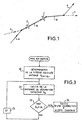
- FIG. 1 illustrates the example of two aircraft 1, 2 along two roads, one a, represented in continuous line, and the other b, shown in dashed lines, borrowing, in the same direction, a common section shown in dashed lines. and consisting of a sequence of two imposed air corridors 10 and 11.
- the aircraft 1 and 2 When arriving at the common sections 10, 11 the aircraft 1 and 2 must be incorporated into existing traffic on these sections without there being collision risks and therefore respect a minimum separation distance between them and other aircraft already present.
- This respect of a minimum separation distance between aircraft, within an air traffic corridor is done by a visual watch of the aircraft crews and by traffic regulation by an air traffic control body in charge of the air corridors concerned. , which gives speed instructions to each aircraft for a steady flow of traffic respecting a minimum safety spacing between each aircraft. Because of the visual surveillance, the minimum spacing of the setpoint between aircraft is a function of the visibility conditions, lower in good visibility than in poor visibility, which plays especially in the approach phase of an airstrip.
- a guiding method usable on board an aircraft having this kind of information for automatic tracking, at an imposed distance, of another aircraft preceding it on its trajectory. Indeed, it can result in the maintenance of all the longitudinal spacings separating the aircraft traversing, one after the other, the same air corridor, by chain application of such a guide method at the level each aircraft to maintain its longitudinal separation from the immediately preceding aircraft.
- each aircraft in the queue must be considered as belonging to two pairs, a pair where it is said "slave aircraft” because it implements the guidance method to maintain its spacing relative to the aircraft preceding it in the queue, and a pair where it is said "master aircraft” because it serves as a reference to the aircraft that follows in the queue for the implementation of the guidance method.
- the common road portions 10, 11 may also be portions of a corridor imposed for the approach of an airstrip.
- This process has two main successive phases: an initialization phase and a servo phase.
- the slave aircraft 2 takes an initial speed value calculated with respect to the air V CAS0, S.
- the speed calculated with respect to the air is a well known size in aeronautics often denominated under its Anglo-Saxon name of "Calculated Air Speed". It corresponds to the speed of the aircraft with respect to the air deduced from the measurements of temperature and static and dynamic pressures, by application of the fundamental laws of aerodynamics.
- This speed calculated with respect to the air is not the true speed compared to the air often designated under its Anglo-Saxon name of "True Air Speed" because it depends on the calibration of the sensors of dynamic and static pressures which are made for an altitude 0 but it is related to the true speed relative to the air by a law depending on the altitude, the temperature and the type of aircraft and joins it as soon as the altitude of the aircraft s approach of zero.
- the slave aircraft 2 which knows, at any moment or in close moments, its location on the trajectory that it shares with the master aircraft 1, for example thanks to its navigation equipment edge, and the location of the master aircraft 1 on their common trajectory, for example by means of an ADS-L system, and which also knows the shape of their common trajectory, periodically deduces an estimate or measure of its effective distance separating D M with respect to the master aircraft 1 on their common trajectory as well as the difference of this measured separation distance D M with a set value D SEP and pulls, at each taking of difference, a correction term E it applies at its speed calculated with respect to the air V CAS, S to reduce this difference or maintain it within an authorized range.
- S of the slave aircraft 2 tends to correct the value of the difference, that is to say goes in the direction of an increase in the speed calculated with respect to the air V CAS, S of the slave aircraft 2 if the measured spacing distance D M tends to increase beyond the minimum setpoint value D SEP and in the direction of a reduction in the speed calculated with respect to the air V CAS, S of the slave aircraft 2 if the measured spacing distance D M tends to fall below the minimum setpoint value D SEP , with a constant of servo time of the order of thirty seconds.
- E ( ( D S E P - D M ) , ( t 0 + ( k - 1 ) ⁇ t ) ) S E P ⁇ M ⁇ ( D S E P - D M ( t 0 + ( k - 1 ) ⁇ t ) )
- M 120 k t s 1 NOT M (kts designating a speed in knots and Nm a nautical mile)
- the coefficient k ' said of safety because it prevents the effective margin of tolerance ⁇ L e to reach the tolerance of setpoint ⁇ L c , can be taken equal to 0.8 while the coefficient k "of hysteresis can be taken equal to 0.5.
- the effective separation distance D M is calculated by the slave aircraft taking into account its position and that of the master aircraft on the path they describe in common. Its geographical position can be provided by various means, for example its own navigation equipment. That of the master aircraft can be communicated to it by means of a cooperative communication system such as ADS-B, but it can also be provided by a non-cooperative system such as an on-board radar or even by a ground radar.
- ADS-B cooperative communication system
- non-cooperative system such as an on-board radar or even by a ground radar.
- the shape of the trajectory traveled jointly by the master and slave aircraft is a given since it is an imposed air corridor. This is usually a succession of straight segments joined by arcs allowing the aircraft to change course between two straight segments.
- the slave aircraft 1 measures its distance from the master aircraft 2 in several steps.
- the slave aircraft 2 calculates its separation distance. longitudinal to the master aircraft 1 in a manner similar to the previous for the portion of straight segment to browse or remaining to go by one of the two aircraft.
- FIG. 2 illustrates a software organization that makes it possible to implement the guidance method that has just been described, by an on-board computer that can also perform other tasks involved in managing the flight.
- This software organization is based on two software layers, the lower one called “Separation Monitoring and Correction” and the other upper 16 called “Operation Manager”.
- the upper layer 16 "Operation Manager” provides the dialogue of the lower software layer 10 "Separation Monitoring and Correction” with the equipment of the aircraft: flight management computer 17 for tracking the corrections of the speed calculated with respect to the air, radiocommunication apparatus 18 for neighborhood traffic monitoring (ADS-B) and for exchanging traffic information with the ATC network, HMI equipment 19 interfacing with the crew, etc. It detects a request by the aircraft for compliance with a minimum separation distance with respect to another designated aircraft, either from the crew via the HMI equipment 19, or from a air traffic control authority sending its request from an ATC air traffic control center via the Control Pilot Data Link Communication (CPDLC) channel of the English language.
- CPDLC Control Pilot Data Link Communication
- FIG. 3 is a flowchart illustrating the main steps of the guidance method as implemented by the lower software layer "Separation Monitoring and Correction" 15.
- the lower software layer “Separation Monitoring and Correction” 15 initializes the guidance method to 20, by choosing the initial value adopted for the speed calculated with respect to the air of the aircraft V CAS0, S which is transmitted as a setpoint to the computer of management of the flight by the upper layer "Operation Manager" 16.
- the distance D M separating the aircraft from the one chosen for the master aircraft tests at 22 if this separation distance D M falls within a tolerance range ⁇ L admitted with respect to a setpoint value D SEP possibly depending on the altitude or a separation time interval with respect to the master aircraft and, the results of the test, ie, if the range is respected, does nothing and triggers a timer 23 before returning to step 21, in calculating the distance D M, ie, finds that the range is not respected and develops in 24 a speed correction term calculated by report to the air of the aircraft to reduce its separation distance within the tolerance range allowed by alerting the crew of a change of speed reference calculated with respect to the air management computer flight.
Landscapes
- Engineering & Computer Science (AREA)
- Aviation & Aerospace Engineering (AREA)
- Physics & Mathematics (AREA)
- General Physics & Mathematics (AREA)
- Radar, Positioning & Navigation (AREA)
- Remote Sensing (AREA)
- Automation & Control Theory (AREA)
- Traffic Control Systems (AREA)
- Radar Systems Or Details Thereof (AREA)
Claims (20)
- Verfahren zur Führung eines "Folge"-Luftfahrzeugs (2) im Rahmen eines Konvoi-Flugs hinter einem anderen, "Leit"-Luftfahrzeug (1) auf der gleichen vorbestimmten Flugbahn und mit einem Mindest-Sollabstand DSEP, das darin besteht, der bezüglich der Luft berechneten Geschwindigkeit VCAS,S des Folge-Luftfahrzeugs einen Ausgangswert VCAS0,S zu verleihen, periodisch den das Folge-Luftfahrzeug (2) vom Leit-Luftfahrzeug (1) trennenden Abstand von der geographischen Position des Folge-Luftfahrzeugs (2) und von derjenigen des Leit-Luftfahrzeugs (1) im gleichen Zeitpunkt und von der bekannten Form der vom Leit-Luftfahrzeug (1) und vom Folge-Luftfahrzeug (2) verfolgten Flugbahn abzuleiten, und dann periodisch die bezüglich der Luft berechnete Geschwindigkeit VCAS,S des Folge-Luftfahrzeugs zu korrigieren, indem sie durch einen Korrekturterm E verändert wird, der aus der Abweichung entnommen wird, die zwischen dem gemessenen Abstand DM und dem Mindest-Sollabstand DSEP festgestellt wurde, gemäß einer Rekurrenzbeziehung folgender Form:

wobei Δt die Periodizität der Korrektur, DM(t0+(k-1)Δt) der im Zeitpunkt (t0+(k-1)Δt) gemessene Abstand ist,
wobei das Verfahren dadurch gekennzeichnet ist, dass ein Toleranzbereich ΔL für den Wert der Abweichung zwischen dem gemessenen Abstand DM und dem berücksichtigten Sollabstand DSEP bezüglich des Sollabstands DSEP vorgesehen wird, innerhalb dessen der Korrekturterm E einen Wert Null annimmt, und außerhalb dessen der Korrekturterm einen Wert proportional zur festgestellten Abweichung zwischen dem gemessenen Abstand DM und dem Mindest-Sollabstand DSEP annimmt. - Verfahren nach Anspruch 1, dadurch gekennzeichnet, dass der Ausgangswert der bezüglich der Luft berechneten Geschwindigkeit des Folge-Luftfahrzeugs (2) gleich der bezüglich der Luft berechneten Geschwindigkeit genommen wird, die bei der Vorbereitung des Flugplans des Folge-Luftfahrzeugs (2) an der Stelle vorgesehen wird, wo es sich zum Zeitpunkt der Anwendung des Führungsverfahrens befindet, wobei diese bezüglich der Luft berechnete Geschwindigkeit aus der Anwendung eines Definitionsgesetzes 4D in Abhängigkeit von den vier Variablen: Höhe, Zeit, Breitengrad und Längengrad resultiert.
- Verfahren nach Anspruch 1, dadurch gekennzeichnet, dass der Ausgangswert der bezüglich der Luft berechneten Geschwindigkeit des Folge-Luftfahrzeugs (2) gleich einer bezüglich der Luft berechneten Geschwindigkeit genommen wird, mit der Folge-Luftfahrzeug (2) im Reiseflug fliegt.
- Verfahren nach Anspruch 1, dadurch gekennzeichnet, dass der Ausgangswert der bezüglich der Luft berechneten Geschwindigkeit des Folge-Luftfahrzeugs (2) gleich der bezüglich der Luft berechneten Geschwindigkeit des Leit-Luftfahrzeugs (1) in dem Moment genommen wird, in dem es im Wesentlichen den gleichen Punkt der Flugbahn durchquert hat.
- Verfahren nach Anspruch 1, dadurch gekennzeichnet, dass ein Hysteresephänomen um den Toleranzbereich ΔLe herum eingeführt wird, indem letzterem bei jeder Erfassung seiner Überschreitung ein reduzierter Wert verliehen wird, und dies, so lange die Überschreitung dauert.
- Verfahren nach Anspruch 1, dadurch gekennzeichnet, dass, wenn es einen Solltoleranzbereich ΔLc gibt, ein strengerer Toleranzbereich ΔLe genommen wird als der Solltoleranzbereich ΔLc, indem an den Solltoleranzbereich ΔLc ein positiver Sicherheitskoeffizient k' niedriger als 1 angewendet wird:

- Verfahren nach Anspruch 6, dadurch gekennzeichnet, dass der Sicherheitskoeffizient k' gleich 0,8 genommen wird.
- Verfahren nach Anspruch 6, dadurch gekennzeichnet, dass ein Hysteresephänomen um den Toleranzbereich ΔLe herum eingeführt wird, indem diesem letzteren, wenn er überschritten wurde, und so lange er überschritten wird, ein reduzierten Wert verliehen wird, der vom Solltoleranzbereich ΔLc durch Anwendung eines positiven Hysteresekoeffizienten k" kleiner als der Sicherheitskoeffizient k' abgeleitet wird.
- Verfahren nach Anspruch 8, dadurch gekennzeichnet, dass der Hysteresekoeffizient k" gleich

genommen wird, wobei k' der Sicherheitskoeffizient ist. - Verfahren nach Anspruch 1, dadurch gekennzeichnet, dass der Korrekturterm E proportional zur festgestellten Abweichung zwischen dem gemessenen Abstand DM und dem Mindest-Sollabstand DSEP mit einem Proportionalitätskoeffizienten p genommen wird, der entspricht:
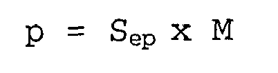
mit:
wobei ΔLc ein Solltoleranz-Prozentsatz, k' ein positiver Sicherheitskoeffizient kleiner als Eins, k" ein Hysteresekoeffizient und M ein Homogenisierungskoeffizient des Abstands bezüglich der Geschwindigkeit ist. - Verfahren nach Anspruch 10, dadurch gekennzeichnet, dass der Homogenisierungskoeffizient M gleich:

genommen wird. - Verfahren nach Anspruch 1, dadurch gekennzeichnet, dass der gemessene Abstand DM die waagrechte Komponente des wahren Abstands ist.
- Verfahren nach Anspruch 1, dadurch gekennzeichnet, dass der gemessene Abstand DM, der in einem gegebenen Zeitpunkt das Folge-Luftfahrzeug (2) vom Leit-Luftfahrzeug (1) auf einer geradlinigen Flugbahn trennt, aus den Lokalisierungen des Leit-Luftfahrzeugs (1) und des Folge-Luftfahrzeugs (2) mit Hilfe folgender Beziehung entnommen wird:

wobei LatM und LongM die geographische Position des Leit-Luftfahrzeugs, LatS und LongS die geographische Position des Folge-Luftfahrzeugs definieren und R der Radius der Erde ist. - Verfahren nach Anspruch 1, dadurch gekennzeichnet, dass der gemessene Abstand DM, der in einem gegebenen Zeitpunkt das Folge-Luftfahrzeug (2) vom Leit-Luftfahrzeug (1) trennt, während das Folge-Luftfahrzeug (2) sich in einem geradlinigen Bereich mit dem Kurs XP der von den beiden Luftfahrzeugen verfolgten Flugbahn und das Leit-Luftfahrzeug (1) sich in einem anderen geradlinigen Bereich mit dem Kurs XS dieser Flugbahn befindet, die miteinander durch einen Kreisbogen mit dem Radius r verbunden sind, der in einem Punkt P1 beginnt, der das Ende des geradlinigen Flugbahnbereichs markiert, der vom Folge-Luftfahrzeug durchflogen wird, und in einem Punkt P2 endet, der den Beginn des geradlinigen Flugbahnbereichs markiert, der vom Leit-Luftfahrzeug durchflogen wird, gleich der Summe der Abstände genommen wird, die das Folge-Luftfahrzeug vom Punkt P1 und den Punkt P2 vom Leit-Luftfahrzeug trennen, erhöht um die Länge L des Kreisbogens, die gleich:

genommen wird, wobei die Kursrichtungen XP und XS in Radian ausgedrückt werden. - Verfahren nach Anspruch 1, dadurch gekennzeichnet, dass der Sollabstand DSEP von einem Sollwert einer Mindestverzögerung ΔT zwischen den Durchgängen der beiden Luftfahrzeuge (1, 2) durch den gleichen Punkt der Flugbahn durch Anwendung der Beziehung:

abgeleitet wird, wobei VTAS,S die wahre Geschwindigkeit des Folge-Luftfahrzeugs in der Luft ist. - Verfahren nach Anspruch 1, dadurch gekennzeichnet, dass der Sollabstand DSEP aus einer Tabelle entnommen wird, die ihn in Abhängigkeit von der Höhe angibt.
- Verfahren nach Anspruch 1, dadurch gekennzeichnet, dass der Sollabstand DSEP ein Abstandssollwert ist, der von einem Fluglotsen vorgegeben wird.
- Verfahren nach Anspruch 1, dadurch gekennzeichnet, dass die Lokalisierung des Leit-Luftfahrzeugs (1) von diesem letzteren mittels eines Systems wie ADS-B kooperativ an das Folge-Luftfahrzeug (2) übertragen wird.
- Verfahren nach Anspruch 1, dadurch gekennzeichnet, dass das Folge-Luftfahrzeug (2) die Lokalisierung des Leit-Luftfahrzeugs (1) mittels eines On-Board-Radars gewinnt.
- Verfahren nach Anspruch 1, dadurch gekennzeichnet, dass das Folge-Luftfahrzeug die Lokalisierung des Leit-Luftfahrzeugs von einer Boden-Lokalisierungsstation gewinnt.
Applications Claiming Priority (3)
| Application Number | Priority Date | Filing Date | Title |
|---|---|---|---|
| FR0013846A FR2816091B1 (fr) | 2000-10-27 | 2000-10-27 | Procede de guidage d'un aeronef dans le cadre d'un vol en convoi |
| FR0013846 | 2000-10-27 | ||
| PCT/FR2001/003254 WO2002035497A1 (fr) | 2000-10-27 | 2001-10-19 | Procede de guidage d"un aeronef dans le cadre d"un vol en convoi |
Publications (2)
| Publication Number | Publication Date |
|---|---|
| EP1330806A1 EP1330806A1 (de) | 2003-07-30 |
| EP1330806B1 true EP1330806B1 (de) | 2006-06-28 |
Family
ID=8855834
Family Applications (1)
| Application Number | Title | Priority Date | Filing Date |
|---|---|---|---|
| EP01980611A Expired - Lifetime EP1330806B1 (de) | 2000-10-27 | 2001-10-19 | Verfahren zur führung eines flugzeugs in einer formation |
Country Status (6)
| Country | Link |
|---|---|
| US (1) | US6587757B2 (de) |
| EP (1) | EP1330806B1 (de) |
| CA (1) | CA2394990C (de) |
| DE (1) | DE60121200T2 (de) |
| FR (1) | FR2816091B1 (de) |
| WO (1) | WO2002035497A1 (de) |
Families Citing this family (29)
| Publication number | Priority date | Publication date | Assignee | Title |
|---|---|---|---|---|
| US7356390B2 (en) | 1999-06-29 | 2008-04-08 | Space Data Corporation | Systems and applications of lighter-than-air (LTA) platforms |
| US10338580B2 (en) * | 2014-10-22 | 2019-07-02 | Ge Global Sourcing Llc | System and method for determining vehicle orientation in a vehicle consist |
| WO2004008266A1 (en) * | 2002-07-16 | 2004-01-22 | Honeywell International Inc. | Vehicle position keeping system |
| US6963795B2 (en) | 2002-07-16 | 2005-11-08 | Honeywell Interntaional Inc. | Vehicle position keeping system |
| WO2005123502A2 (en) * | 2003-12-12 | 2005-12-29 | Advanced Ceramics Research, Inc. | Unmanned vehicle |
| US20050230563A1 (en) * | 2004-02-21 | 2005-10-20 | Corcoran James J Iii | Automatic formation flight control system |
| US6926233B1 (en) * | 2004-02-21 | 2005-08-09 | Corcoran, Iii James John | Automatic formation flight control system (AFFCS)—a system for automatic formation flight control of vehicles not limited to aircraft, helicopters, or space platforms |
| EP1897079A1 (de) * | 2005-06-13 | 2008-03-12 | Aviation Communication & Surveillance Systems, LLC | Abstandssteuerungssystem und -verfahren für ein flugzeug |
| DE102005038017B3 (de) * | 2005-08-09 | 2007-05-10 | Eads Deutschland Gmbh | Verfahren zur Flugführung mehrerer im Verband fliegender Flugzeuge |
| FR2894056B1 (fr) * | 2005-11-25 | 2011-04-15 | Thales Sa | Procede de gestion de vol et convoi |
| FR2897959B1 (fr) * | 2006-02-28 | 2008-04-04 | Airbus France Sas | Dispositif d'aide au guidage d'un aeronef suiveur faisant partie d'une patrouille, ainsi qu'un systeme d'aide a un vol en patrouille comportant un tel dispositif. |
| FR2907952B1 (fr) * | 2006-10-26 | 2008-12-19 | Airbus France Sa | Procede et dispositif d'aide au guidage d'un aeronef le long d'une trajectoire de vol. |
| FR2907953B1 (fr) * | 2006-10-26 | 2008-12-19 | Airbus France Sa | Systeme de guidage d'un aeronef. |
| US7912593B2 (en) * | 2007-04-02 | 2011-03-22 | Aviation Communication & Surveillance Systems, Llc | Merging and spacing speed target calculation |
| FR2931983B1 (fr) | 2008-06-02 | 2018-04-06 | Airbus Operations | Methode et systeme de gestion automatique d'un convoi d'aeronefs roulant au sol. |
| FR2939946B1 (fr) | 2008-12-12 | 2016-05-27 | Thales Sa | Procede et systeme d'aide a la gestion de l'espacement relatif entre aeronefs |
| FR2942566B1 (fr) * | 2009-02-24 | 2016-01-22 | Thales Sa | Procede pour la gestion du vol d'un aeronef |
| IT1394782B1 (it) * | 2009-03-03 | 2012-07-13 | Alenia Aeronautica Spa | Procedimento di predizione di collisioni tra un velivolo e un aeromobile |
| FR2959316B1 (fr) * | 2010-04-21 | 2012-05-18 | Airbus Operations Sas | Procede et dispositif d'estimation automatique d'une vitesse air d'un avion |
| US9135829B2 (en) * | 2010-04-30 | 2015-09-15 | The Boeing Company | Distance separation criteria indicator |
| WO2012002976A1 (en) * | 2010-07-01 | 2012-01-05 | Mearthane Products Corporation | High performance resilient skate wheel with compression modulus gradient |
| US9761148B2 (en) * | 2010-08-03 | 2017-09-12 | Honeywell International Inc. | Airborne separation assurance system and required time of arrival function cooperation |
| KR101711025B1 (ko) * | 2011-04-21 | 2017-02-28 | 한국전자통신연구원 | 우선 관제 대상 선정 장치와 방법 및 대상물 관제 장치 |
| US9384667B2 (en) | 2014-07-17 | 2016-07-05 | Honeywell International Inc. | Scalar product based spacing calculation |
| US9998360B2 (en) * | 2014-11-17 | 2018-06-12 | Honeywell International Inc. | Minimizining message propagation times when brief datalink interruptions occur |
| US9660719B2 (en) | 2014-11-17 | 2017-05-23 | Honeywell International Inc. | Minimizing propagation times of queued-up datalink TPDUs |
| US9711055B2 (en) * | 2015-06-08 | 2017-07-18 | Honeywell International Inc. | Flight management mode transitioning for aircraft trajectory management |
| US12020579B2 (en) * | 2021-05-28 | 2024-06-25 | Rockwell Collins, Inc. | System and method for flying aircraft relative to lead aircraft |
| CN113506445B (zh) * | 2021-09-13 | 2021-11-30 | 四川国蓝中天环境科技集团有限公司 | 考虑出行者长期遵从行为变化的实时交通诱导系统及方法 |
Family Cites Families (14)
| Publication number | Priority date | Publication date | Assignee | Title |
|---|---|---|---|---|
| DE2148764A1 (de) * | 1971-09-30 | 1973-04-05 | Licentia Gmbh | Kollisionsverhuetungssystem der luftfahrt |
| GB1536547A (en) * | 1976-08-10 | 1978-12-20 | Ferranti Ltd | Aircraft guidance systems |
| US4674710A (en) * | 1985-10-17 | 1987-06-23 | The United States Of America As Represented By The Secretary Of The Air Force | Automatic formation turns |
| DE3809538A1 (de) * | 1988-03-22 | 1989-10-19 | Messerschmitt Boelkow Blohm | Steuerungs- und leitsystem |
| FR2632755B1 (fr) | 1988-06-08 | 1994-05-27 | Thomson Csf | Systeme d'aide au deplacement de mobiles en formation groupee |
| US5521817A (en) * | 1994-08-08 | 1996-05-28 | Honeywell Inc. | Airborne drone formation control system |
| FR2749933B1 (fr) | 1996-06-14 | 1998-09-11 | Sextant Avionique | Procede pour la gestion de la vitesse air en vue du respect des contraintes de temps d'un aerodyne dans un environnement meteorologique evolutif |
| US5906336A (en) * | 1997-11-14 | 1999-05-25 | Eckstein; Donald | Method and apparatus for temporarily interconnecting an unmanned aerial vehicle |
| US6271768B1 (en) * | 1998-12-30 | 2001-08-07 | Honeywell Inc. | Vertical speed indicator/traffic resolution advisory display for TCAS |
| US6262679B1 (en) * | 1999-04-08 | 2001-07-17 | Honeywell International Inc. | Midair collision avoidance system |
| US6393358B1 (en) * | 1999-07-30 | 2002-05-21 | The United States Of America As Represented By The Administrator Of The National Aeronautics And Space Administration | En route spacing system and method |
| US6785610B2 (en) * | 1999-12-21 | 2004-08-31 | Lockheed Martin Corporation | Spatial avoidance method and apparatus |
| US6795772B2 (en) * | 2001-06-23 | 2004-09-21 | American Gnc Corporation | Method and system for intelligent collision detection and warning |
| US6657578B2 (en) * | 2001-07-20 | 2003-12-02 | Aviation Communication & Surveillance Systems, Llc | Formation surveillance and collision avoidance |
-
2000
- 2000-10-27 FR FR0013846A patent/FR2816091B1/fr not_active Expired - Fee Related
-
2001
- 2001-10-19 EP EP01980611A patent/EP1330806B1/de not_active Expired - Lifetime
- 2001-10-19 WO PCT/FR2001/003254 patent/WO2002035497A1/fr not_active Ceased
- 2001-10-19 CA CA2394990A patent/CA2394990C/fr not_active Expired - Fee Related
- 2001-10-19 US US10/148,904 patent/US6587757B2/en not_active Expired - Lifetime
- 2001-10-19 DE DE60121200T patent/DE60121200T2/de not_active Expired - Fee Related
Also Published As
| Publication number | Publication date |
|---|---|
| DE60121200D1 (de) | 2006-08-10 |
| EP1330806A1 (de) | 2003-07-30 |
| WO2002035497A1 (fr) | 2002-05-02 |
| FR2816091A1 (fr) | 2002-05-03 |
| US6587757B2 (en) | 2003-07-01 |
| DE60121200T2 (de) | 2007-05-24 |
| FR2816091B1 (fr) | 2003-01-31 |
| US20020183900A1 (en) | 2002-12-05 |
| CA2394990C (fr) | 2010-08-10 |
| CA2394990A1 (fr) | 2002-05-02 |
Similar Documents
| Publication | Publication Date | Title |
|---|---|---|
| EP1330806B1 (de) | Verfahren zur führung eines flugzeugs in einer formation | |
| CA2381574C (fr) | Procede d'elaboration d'une trajectoire d'evitement dans le plan horizontal pour aeronef en vue de la resolution d'un conflit de trafic | |
| US11551564B2 (en) | Aircraft with landing system | |
| EP3323028B1 (de) | Verfahren zur automatischen unterstützung der landung eines flugzeuges | |
| EP1570325B1 (de) | Verfahren zur validierung einer flugplaneinschränkung | |
| CA2262380C (fr) | Dispositif d'assistance au guidage d'un vehicule sur une trajectoire | |
| WO2010055218A1 (fr) | Procede et dispositif d'aide au pilotage d'un aeronef lors d'une phase d'atterrissage | |
| WO2007054448A1 (fr) | Systeme d'evitement de terrain pour aeronefs de transport | |
| FR2905756A1 (fr) | Procede et dispositif pour aeronef,d'evitement des collisions avec le terrain | |
| FR2936077A1 (fr) | Procede et dispositif d'aide au pilotage d'un aeronef lors d'une phase d'atterrissage. | |
| US11657721B1 (en) | Aircraft with flight assistant | |
| EP0902878A1 (de) | Kurskorrekturmethode zur steuerung eines fahrzeuges und anwendung dieser methode zur seitlichen vermeidung einer zone | |
| FR2949897A1 (fr) | Procede d'assistance au pilotage d'un aeronef et dispositif correspondant. | |
| EP2662743B1 (de) | Verfahren und Vorrichtung zur Unterstützung der Flugsteuerung eines Luftfahrzeugs während einer Landephase | |
| FR2894368A1 (fr) | Dispositif et procede de construction automatisee de trajectoire d'urgence pour aeronefs | |
| EP2150777A1 (de) | Anzeigevorrichtung für ein flugzeug mit mitteln zur anzeige einer steuerungssymbologie zur vermeidung von hindernissen | |
| FR2906921A1 (fr) | Procede de formation d'une trajectoire d'urgence en 3d pour aeronef et dispositif de mise en oeuvre | |
| FR2935521A1 (fr) | Procede de verification de la coherence des parametres de decollage d'un aeronef avec une longueur de piste disponible | |
| FR2983619A1 (fr) | Procede, dispositif et systeme pour garantir un espacement temporel entre un aeronef et au moins un trafic cible | |
| FR2948468A1 (fr) | Procede et dispositif d'aide au controle lateral d'aeronef lors d'une phase d'approche | |
| US12260769B1 (en) | System and apparatus for reducing the urgency of a flight condition | |
| FR2909461A1 (fr) | Procede et dispositif de decollage automatique d'un avion. | |
| WO2022219007A1 (fr) | Adaptation automatique du profil vertical d'un aeronef en fonction d'une incertitude de position | |
| FR2909460A1 (fr) | Procede de remplacement de segments dans une procedure de navigation aerienne | |
| EP3770626A1 (de) | Verfahren zur validierung mindestens einer vorbestimmten positionsdateninformation, die in einer datenbank eines luftfahrzeugs gespeichert ist, entsprechendes computerprogramm und entsprechende vorrichtung |
Legal Events
| Date | Code | Title | Description |
|---|---|---|---|
| PUAI | Public reference made under article 153(3) epc to a published international application that has entered the european phase |
Free format text: ORIGINAL CODE: 0009012 |
|
| 17P | Request for examination filed |
Effective date: 20020717 |
|
| AK | Designated contracting states |
Designated state(s): AT BE CH CY DE DK ES FI FR GB GR IE IT LI LU MC NL PT SE TR |
|
| RBV | Designated contracting states (corrected) |
Designated state(s): DE ES FR GB |
|
| 17Q | First examination report despatched |
Effective date: 20040727 |
|
| GRAP | Despatch of communication of intention to grant a patent |
Free format text: ORIGINAL CODE: EPIDOSNIGR1 |
|
| GRAC | Information related to communication of intention to grant a patent modified |
Free format text: ORIGINAL CODE: EPIDOSCIGR1 |
|
| GRAS | Grant fee paid |
Free format text: ORIGINAL CODE: EPIDOSNIGR3 |
|
| GRAA | (expected) grant |
Free format text: ORIGINAL CODE: 0009210 |
|
| AK | Designated contracting states |
Kind code of ref document: B1 Designated state(s): DE ES FR GB |
|
| REG | Reference to a national code |
Ref country code: GB Ref legal event code: FG4D Free format text: NOT ENGLISH |
|
| REF | Corresponds to: |
Ref document number: 60121200 Country of ref document: DE Date of ref document: 20060810 Kind code of ref document: P |
|
| PG25 | Lapsed in a contracting state [announced via postgrant information from national office to epo] |
Ref country code: ES Free format text: LAPSE BECAUSE OF FAILURE TO SUBMIT A TRANSLATION OF THE DESCRIPTION OR TO PAY THE FEE WITHIN THE PRESCRIBED TIME-LIMIT Effective date: 20061009 |
|
| GBT | Gb: translation of ep patent filed (gb section 77(6)(a)/1977) |
Effective date: 20061004 |
|
| PLBE | No opposition filed within time limit |
Free format text: ORIGINAL CODE: 0009261 |
|
| STAA | Information on the status of an ep patent application or granted ep patent |
Free format text: STATUS: NO OPPOSITION FILED WITHIN TIME LIMIT |
|
| 26N | No opposition filed |
Effective date: 20070329 |
|
| PGFP | Annual fee paid to national office [announced via postgrant information from national office to epo] |
Ref country code: DE Payment date: 20081016 Year of fee payment: 8 |
|
| PGFP | Annual fee paid to national office [announced via postgrant information from national office to epo] |
Ref country code: GB Payment date: 20091014 Year of fee payment: 9 |
|
| PG25 | Lapsed in a contracting state [announced via postgrant information from national office to epo] |
Ref country code: DE Free format text: LAPSE BECAUSE OF NON-PAYMENT OF DUE FEES Effective date: 20100501 |
|
| GBPC | Gb: european patent ceased through non-payment of renewal fee |
Effective date: 20101019 |
|
| PG25 | Lapsed in a contracting state [announced via postgrant information from national office to epo] |
Ref country code: GB Free format text: LAPSE BECAUSE OF NON-PAYMENT OF DUE FEES Effective date: 20101019 |
|
| REG | Reference to a national code |
Ref country code: FR Ref legal event code: PLFP Year of fee payment: 16 |
|
| REG | Reference to a national code |
Ref country code: FR Ref legal event code: PLFP Year of fee payment: 17 |
|
| PGFP | Annual fee paid to national office [announced via postgrant information from national office to epo] |
Ref country code: FR Payment date: 20170929 Year of fee payment: 17 |
|
| PG25 | Lapsed in a contracting state [announced via postgrant information from national office to epo] |
Ref country code: FR Free format text: LAPSE BECAUSE OF NON-PAYMENT OF DUE FEES Effective date: 20181031 |