EP1332938A2 - Dispositif de valve actionnable électromagnétiquement ainsi qu'un agencement pour commander un tel dispositif de valve - Google Patents
Dispositif de valve actionnable électromagnétiquement ainsi qu'un agencement pour commander un tel dispositif de valve Download PDFInfo
- Publication number
- EP1332938A2 EP1332938A2 EP02026734A EP02026734A EP1332938A2 EP 1332938 A2 EP1332938 A2 EP 1332938A2 EP 02026734 A EP02026734 A EP 02026734A EP 02026734 A EP02026734 A EP 02026734A EP 1332938 A2 EP1332938 A2 EP 1332938A2
- Authority
- EP
- European Patent Office
- Prior art keywords
- valve device
- arrangement
- magnetic coil
- valve
- electromagnet
- Prior art date
- Legal status (The legal status is an assumption and is not a legal conclusion. Google has not performed a legal analysis and makes no representation as to the accuracy of the status listed.)
- Withdrawn
Links
Images

Classifications
-
- F—MECHANICAL ENGINEERING; LIGHTING; HEATING; WEAPONS; BLASTING
- F16—ENGINEERING ELEMENTS AND UNITS; GENERAL MEASURES FOR PRODUCING AND MAINTAINING EFFECTIVE FUNCTIONING OF MACHINES OR INSTALLATIONS; THERMAL INSULATION IN GENERAL
- F16K—VALVES; TAPS; COCKS; ACTUATING-FLOATS; DEVICES FOR VENTING OR AERATING
- F16K31/00—Actuating devices; Operating means; Releasing devices
- F16K31/02—Actuating devices; Operating means; Releasing devices electric; magnetic
- F16K31/06—Actuating devices; Operating means; Releasing devices electric; magnetic using a magnet, e.g. diaphragm valves, cutting off by means of a liquid
- F16K31/0675—Electromagnet aspects, e.g. electric supply therefor
- F16K31/0679—Electromagnet aspects, e.g. electric supply therefor with more than one energising coil
-
- B—PERFORMING OPERATIONS; TRANSPORTING
- B60—VEHICLES IN GENERAL
- B60T—VEHICLE BRAKE CONTROL SYSTEMS OR PARTS THEREOF; BRAKE CONTROL SYSTEMS OR PARTS THEREOF, IN GENERAL; ARRANGEMENT OF BRAKING ELEMENTS ON VEHICLES IN GENERAL; PORTABLE DEVICES FOR PREVENTING UNWANTED MOVEMENT OF VEHICLES; VEHICLE MODIFICATIONS TO FACILITATE COOLING OF BRAKES
- B60T8/00—Arrangements for adjusting wheel-braking force to meet varying vehicular or ground-surface conditions, e.g. limiting or varying distribution of braking force
- B60T8/32—Arrangements for adjusting wheel-braking force to meet varying vehicular or ground-surface conditions, e.g. limiting or varying distribution of braking force responsive to a speed condition, e.g. acceleration or deceleration
- B60T8/34—Arrangements for adjusting wheel-braking force to meet varying vehicular or ground-surface conditions, e.g. limiting or varying distribution of braking force responsive to a speed condition, e.g. acceleration or deceleration having a fluid pressure regulator responsive to a speed condition
- B60T8/36—Arrangements for adjusting wheel-braking force to meet varying vehicular or ground-surface conditions, e.g. limiting or varying distribution of braking force responsive to a speed condition, e.g. acceleration or deceleration having a fluid pressure regulator responsive to a speed condition including a pilot valve responding to an electromagnetic force
-
- B—PERFORMING OPERATIONS; TRANSPORTING
- B60—VEHICLES IN GENERAL
- B60T—VEHICLE BRAKE CONTROL SYSTEMS OR PARTS THEREOF; BRAKE CONTROL SYSTEMS OR PARTS THEREOF, IN GENERAL; ARRANGEMENT OF BRAKING ELEMENTS ON VEHICLES IN GENERAL; PORTABLE DEVICES FOR PREVENTING UNWANTED MOVEMENT OF VEHICLES; VEHICLE MODIFICATIONS TO FACILITATE COOLING OF BRAKES
- B60T8/00—Arrangements for adjusting wheel-braking force to meet varying vehicular or ground-surface conditions, e.g. limiting or varying distribution of braking force
- B60T8/32—Arrangements for adjusting wheel-braking force to meet varying vehicular or ground-surface conditions, e.g. limiting or varying distribution of braking force responsive to a speed condition, e.g. acceleration or deceleration
- B60T8/34—Arrangements for adjusting wheel-braking force to meet varying vehicular or ground-surface conditions, e.g. limiting or varying distribution of braking force responsive to a speed condition, e.g. acceleration or deceleration having a fluid pressure regulator responsive to a speed condition
- B60T8/36—Arrangements for adjusting wheel-braking force to meet varying vehicular or ground-surface conditions, e.g. limiting or varying distribution of braking force responsive to a speed condition, e.g. acceleration or deceleration having a fluid pressure regulator responsive to a speed condition including a pilot valve responding to an electromagnetic force
- B60T8/3615—Electromagnetic valves specially adapted for anti-lock brake and traction control systems
- B60T8/363—Electromagnetic valves specially adapted for anti-lock brake and traction control systems in hydraulic systems
- B60T8/3645—Electromagnetic valves specially adapted for anti-lock brake and traction control systems in hydraulic systems having more than one electromagnetic coil inside a common housing
-
- B—PERFORMING OPERATIONS; TRANSPORTING
- B60—VEHICLES IN GENERAL
- B60T—VEHICLE BRAKE CONTROL SYSTEMS OR PARTS THEREOF; BRAKE CONTROL SYSTEMS OR PARTS THEREOF, IN GENERAL; ARRANGEMENT OF BRAKING ELEMENTS ON VEHICLES IN GENERAL; PORTABLE DEVICES FOR PREVENTING UNWANTED MOVEMENT OF VEHICLES; VEHICLE MODIFICATIONS TO FACILITATE COOLING OF BRAKES
- B60T8/00—Arrangements for adjusting wheel-braking force to meet varying vehicular or ground-surface conditions, e.g. limiting or varying distribution of braking force
- B60T8/32—Arrangements for adjusting wheel-braking force to meet varying vehicular or ground-surface conditions, e.g. limiting or varying distribution of braking force responsive to a speed condition, e.g. acceleration or deceleration
- B60T8/34—Arrangements for adjusting wheel-braking force to meet varying vehicular or ground-surface conditions, e.g. limiting or varying distribution of braking force responsive to a speed condition, e.g. acceleration or deceleration having a fluid pressure regulator responsive to a speed condition
- B60T8/36—Arrangements for adjusting wheel-braking force to meet varying vehicular or ground-surface conditions, e.g. limiting or varying distribution of braking force responsive to a speed condition, e.g. acceleration or deceleration having a fluid pressure regulator responsive to a speed condition including a pilot valve responding to an electromagnetic force
- B60T8/3615—Electromagnetic valves specially adapted for anti-lock brake and traction control systems
- B60T8/3655—Continuously controlled electromagnetic valves
- B60T8/366—Valve details
- B60T8/367—Seat valves, e.g. poppet valves
-
- F—MECHANICAL ENGINEERING; LIGHTING; HEATING; WEAPONS; BLASTING
- F15—FLUID-PRESSURE ACTUATORS; HYDRAULICS OR PNEUMATICS IN GENERAL
- F15B—SYSTEMS ACTING BY MEANS OF FLUIDS IN GENERAL; FLUID-PRESSURE ACTUATORS, e.g. SERVOMOTORS; DETAILS OF FLUID-PRESSURE SYSTEMS, NOT OTHERWISE PROVIDED FOR
- F15B13/00—Details of servomotor systems ; Valves for servomotor systems
- F15B13/02—Fluid distribution or supply devices characterised by their adaptation to the control of servomotors
- F15B13/04—Fluid distribution or supply devices characterised by their adaptation to the control of servomotors for use with a single servomotor
- F15B13/044—Fluid distribution or supply devices characterised by their adaptation to the control of servomotors for use with a single servomotor operated by electrically-controlled means, e.g. solenoids, torque-motors
- F15B13/0442—Fluid distribution or supply devices characterised by their adaptation to the control of servomotors for use with a single servomotor operated by electrically-controlled means, e.g. solenoids, torque-motors with proportional solenoid allowing stable intermediate positions
-
- F—MECHANICAL ENGINEERING; LIGHTING; HEATING; WEAPONS; BLASTING
- F15—FLUID-PRESSURE ACTUATORS; HYDRAULICS OR PNEUMATICS IN GENERAL
- F15B—SYSTEMS ACTING BY MEANS OF FLUIDS IN GENERAL; FLUID-PRESSURE ACTUATORS, e.g. SERVOMOTORS; DETAILS OF FLUID-PRESSURE SYSTEMS, NOT OTHERWISE PROVIDED FOR
- F15B20/00—Safety arrangements for fluid actuator systems; Applications of safety devices in fluid actuator systems; Emergency measures for fluid actuator systems
- F15B20/002—Electrical failure
-
- G—PHYSICS
- G05—CONTROLLING; REGULATING
- G05D—SYSTEMS FOR CONTROLLING OR REGULATING NON-ELECTRIC VARIABLES
- G05D16/00—Control of fluid pressure
- G05D16/20—Control of fluid pressure characterised by the use of electric means
- G05D16/2006—Control of fluid pressure characterised by the use of electric means with direct action of electric energy on controlling means
- G05D16/2013—Control of fluid pressure characterised by the use of electric means with direct action of electric energy on controlling means using throttling means as controlling means
- G05D16/2024—Control of fluid pressure characterised by the use of electric means with direct action of electric energy on controlling means using throttling means as controlling means the throttling means being a multiple-way valve
Definitions
- a generic valve device is from the DE 197 17 807 A1 known.
- the invention enables the in a very elegant way Realization of two separate control circuits for an actuator in a safety-critical Plant, e.g. B. a brake system.
- the actuator d. H. in a brake system, a brake cylinder can from an electromagnetically actuated valve device according to claim 1 with the brake pressure medium be charged.
- the valve device enables due to their two magnetic coil devices the Feeding of two separate electrical signals, for example from separate electrical control circuits can be won.
- Coupling of the magnetic flux of the magnetic coil devices is an operation of the valve device even in the event of a permanently disturbed electrical Control signal of one of the magnetic coil devices still possible, via the other magnetic coil device to bring about a corresponding counteraction and thereby the continued operation of the brake system to enable.
- the valve device according to the invention can be particularly advantageous as a pilot valve for a Relay valve in a trailer control valve in the Brake system of a truck can be used.
- the first and the second magnetic coil device a common anchor on the mechanical for actuation acts on the valve device.
- the coils of the first and second magnetic coil devices on a common winding core wound. This can increase the number of required Components, as well as through the common anchor, relative be kept low.
- the magnetic coil devices are in the same direction wound on the winding core. As a result, a best possible freedom of interaction between the windings can be achieved.
- a third magnetic coil device which mechanically or electromagnetically on the anchor the first and / or the second magnetic coil device acts.
- the third magnetic coil device can Use of the valve devices of a brake system advantageous for realizing the parking brake function be used.
- the third magnetic coil device is the third magnetic coil device as currentless actuating the valve device Proportional magnet. This can the function with the valve device in a simple manner the parking brake even when the vehicle is parked, d. H. with the power supply switched off, be maintained.
- the third magnetic coil device can do this alternatively in an advantageous manner also together with the anchor assigned to it as bistable Electromagnet be formed.
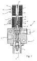
- the valve device (20) shows a valve device (20) with a Proportional control valve (1) of conventional design.
- the proportional control valve (1) has a pressure medium inlet (2), a pressure medium outlet (3) and a vent (4) on.
- the proportional control valve (1) is used for continuous or fine adjustment of a desired Pressure medium flow or a resulting one Pressure at its pressure medium outlet (3) an essentially proportional characteristic.
- the valve device (20) can be used as a pilot valve Actuation of a relay valve (not shown) serve which a brake pressure with a large nominal size controls in a trailer brake system.
- the proportional control valve (1) has a continuously adjustable, longitudinally displaceable plunger (5) mechanically from an electromagnetic device (6) by means of an anchor acting on the plunger (5) (8) can be actuated against a spring force.
- the electromagnetic device (6) next to the armature (8) first magnetic coil device (39) and a second magnetic coil device (43).
- the coil turns of the Magnetic coil devices (39, 43) are on a common Winding core (18), which is essentially concentric is arranged to the anchor (8), wound up.
- the sense of winding is the first and the second magnetic coil device (39, 43) preferably chosen in the same direction.
- the contact pins (14) are the first and the second Magnetic coil device (39, 43) with a not shown electrical connector with other electrical Units connectable.
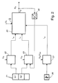
- FIG. 2 schematically shows a preferred arrangement for controlling a valve device (20) according to FIG. 1 in an electrically controlled brake system.
- a brake value transmitter (21) which detects a brake pedal actuation by the driver of a vehicle and is of redundant design for safety reasons, transmits the detected braking request of the driver in the form of two brake value signals (G1, G2) to a first electronic control device (22) and to a second one electronic control device (23).
- the brake value signals (G1, G2) each provide the same information in error-free operation, ie one of the brake value signals (G1, G2) is provided as redundancy.
- the first electronic control device (22) is fed by a first supply voltage (U BI )
- the second electronic control device (23) is fed by a second supply voltage (U BII ), which is independent of the first supply voltage (U BI ) is.
- the first electronic control device (22) delivers a first control current (I 42 ) to the valve device (20).
- the second electronic control device (23) delivers a second control current (I 41 ) to the valve device (20).
- a brake value transmitter (26) is also provided for the parking brake function.
- the latter outputs a parking brake value signal to a third electronic control device (27) for controlling the parking brake function.
- the third electronic control device (27) can be supplied, for example, by the second supply voltage (U BII ), or also by an independent third supply voltage (U BII ) provided for this purpose.
- the third electronic control device (27) outputs a third control current (I 43 ) to the further electromagnetic device (7) of the valve device (20) provided for the parking brake function.
- the valve device (20) is acted upon by an inlet pressure (P III ) at the pressure medium inlet (2).
- a pressure signal (P 22 ) is emitted at the pressure medium outlet (3) to downstream parts of the pressure medium system, in particular to a trailer brake system.
- the pressure signal (P 22 ) emitted is fed back into the second electronic control device (23) via a pressure sensor (25).
- the second electronic control device (23) then carries out a pressure control of the pressure signal (P 22 ) emitted in the sense of a control circuit with the brake value signal (G2) as the desired value.
- 3 shows approximately symbolically the valve device in the middle area (20) with the circuit diagram of a coupled transformer, however for simplicity without the parts for the Parking brake function. To the left are those for following explanation relevant parts of the second electronic control device (23), to the right of it the relevant for the following explanation Parts of the first electronic control device (22).
- the second electronic control device (23) has a microprocessor (30), to which, in addition to the pressure sensor (25) already mentioned, semiconductor switching devices (31, 32, 34, 35) which can be actuated by the microprocessor (30) are connected.
- the first magnetic coil device (39) is connected with its one electrical connection to the switching devices (31, 32) and with its other electrical connection to the switching devices (34, 35) via a resistor (37) used for current detection.
- the switching devices (31, 32, 34, 35) form a full-bridge circuit, with which the magnetic coil device (39) can be connected to the potentials of the second supply voltage (U BII ) and ground in such a way that they can be reversed.
- the switching devices (31, 34) are connected to the second supply voltage (U BII ), the switching devices (32, 35) to the ground potential.
- the control connections of the switching devices (31, 32, 34, 35) are connected to the microprocessor (30).
- the current flow and thus also the magnetic flux in the magnetic coil device (39) can be controlled by clocked actuation of the switching devices (31, 32, 34) via free-wheeling diodes (33, 36) arranged in parallel with the respective switching device (32, 35) connected to the ground potential , 35) are essentially maintained during the breaks.
- By actuating the switching devices (31, 32, 34, 35) in a correspondingly high-frequency manner, an almost continuous current setting of the current (I 41 ) flowing through the magnetic coil device (39) is possible in both directions of current flow.
- the microprocessor (30) can also detect the current flowing through the solenoid coil means (39) current (I 41), and perform in accordance with a control of the current (I 41).
- the parts represented by the control device (22) comprise a microprocessor (40), a semiconductor switching device (41) and a free-wheeling diode (42).
- the switching device (41) is connected on the one hand to the first supply voltage (U BI ) and on the other hand to the second magnetic coil device (43).
- a control connection of the switching device (41) is connected to the microprocessor (40).
- the current (I 42 ) can be applied to the second magnetic coil device (43) as a result of control signals from the microprocessor (40) via the switching device (41).
- the free-wheeling diode (42) in turn serves to maintain the current flow in switching breaks of the switching device (41).
Landscapes
- Physics & Mathematics (AREA)
- Engineering & Computer Science (AREA)
- Fluid Mechanics (AREA)
- Electromagnetism (AREA)
- Mechanical Engineering (AREA)
- General Engineering & Computer Science (AREA)
- Transportation (AREA)
- General Physics & Mathematics (AREA)
- Automation & Control Theory (AREA)
- Chemical & Material Sciences (AREA)
- Analytical Chemistry (AREA)
- Magnetically Actuated Valves (AREA)
- Valves And Accessory Devices For Braking Systems (AREA)
Applications Claiming Priority (2)
| Application Number | Priority Date | Filing Date | Title |
|---|---|---|---|
| DE10204553A DE10204553A1 (de) | 2002-02-05 | 2002-02-05 | Elektromagnetisch betätigbare Ventileinrichtung sowie Anordnung zur Ansteuerung einer solchen Ventileinrichtung |
| DE10204553 | 2002-02-05 |
Publications (2)
| Publication Number | Publication Date |
|---|---|
| EP1332938A2 true EP1332938A2 (fr) | 2003-08-06 |
| EP1332938A3 EP1332938A3 (fr) | 2004-03-17 |
Family
ID=7713675
Family Applications (1)
| Application Number | Title | Priority Date | Filing Date |
|---|---|---|---|
| EP02026734A Withdrawn EP1332938A3 (fr) | 2002-02-05 | 2002-11-30 | Dispositif de valve actionnable électromagnétiquement ainsi qu'un agencement pour commander un tel dispositif de valve |
Country Status (2)
| Country | Link |
|---|---|
| EP (1) | EP1332938A3 (fr) |
| DE (1) | DE10204553A1 (fr) |
Cited By (3)
| Publication number | Priority date | Publication date | Assignee | Title |
|---|---|---|---|---|
| WO2019068501A1 (fr) * | 2017-10-06 | 2019-04-11 | Continental Teves Ag & Co. Ohg | Agencement de soupapes et système de freinage |
| WO2020060180A1 (fr) * | 2018-09-19 | 2020-03-26 | 주식회사 만도 | Dispositif de frein et procédé de commande associé |
| CN115703442A (zh) * | 2021-08-12 | 2023-02-17 | 芜湖伯特利汽车安全系统股份有限公司 | 具备冗余控制功能的车辆制动系统及其控制方法 |
Families Citing this family (2)
| Publication number | Priority date | Publication date | Assignee | Title |
|---|---|---|---|---|
| DE102006047440A1 (de) * | 2006-10-07 | 2008-04-10 | Continental Teves Ag & Co. Ohg | Elektromagnetventil |
| DE102016208966A1 (de) * | 2016-05-24 | 2017-11-30 | Robert Bosch Gmbh | Elektronisch druckregelbare Fahrzeugbremsanlage und Verfahren zur Steuerung einer elektronisch druckregelbaren Fahrzeugbremsanlage |
Family Cites Families (12)
| Publication number | Priority date | Publication date | Assignee | Title |
|---|---|---|---|---|
| US2983285A (en) * | 1959-06-05 | 1961-05-09 | Lawrence H Gardner | Solenoid operated valve |
| DE1775713A1 (de) * | 1968-09-13 | 1971-08-12 | Herion Werke Kg | Elektromagnetventil |
| JPS5576746A (en) * | 1978-12-06 | 1980-06-10 | Keihin Seiki Mfg Co Ltd | Braking device for automobile |
| DE3241521A1 (de) * | 1982-11-10 | 1984-05-10 | Robert Bosch Gmbh, 7000 Stuttgart | Proportionalmagnet |
| DE3521446A1 (de) * | 1985-06-14 | 1986-12-18 | Knorr-Bremse AG, 8000 München | Schaltungsanordnung zur erkennung eines leitungsbruches bei einer elektro-pneumatischen fahrzeugbremsanlage mit vom zugfahrzeug gesteuerter anhaengerbremse |
| DE3527174A1 (de) * | 1985-07-30 | 1987-02-12 | Bosch Gmbh Robert | Doppeltwirkendes magnetventil |
| US4807516A (en) * | 1987-04-23 | 1989-02-28 | The Boeing Company | Flight control system employing three controllers operating a dual actuator |
| DE3913860A1 (de) * | 1989-04-27 | 1990-10-31 | Bosch Gmbh Robert | Druckmittel-fahrzeugbremsanlage |
| US5218996A (en) * | 1992-04-06 | 1993-06-15 | Fasco Controls Corporation | Three-way three-position solenoid valve |
| DE19607773A1 (de) * | 1996-03-01 | 1997-09-04 | Bosch Gmbh Robert | Elektromagnetisch betätigtes Wegeventil |
| DE19717807B4 (de) * | 1997-04-26 | 2005-10-27 | Bosch Rexroth Ag | Von mindestens einem Elektromagneten betätigbares Wegeventil |
| JP2001003770A (ja) * | 1999-06-16 | 2001-01-09 | Unisia Jecs Corp | 電動式スロットルバルブ装置 |
-
2002
- 2002-02-05 DE DE10204553A patent/DE10204553A1/de not_active Withdrawn
- 2002-11-30 EP EP02026734A patent/EP1332938A3/fr not_active Withdrawn
Cited By (7)
| Publication number | Priority date | Publication date | Assignee | Title |
|---|---|---|---|---|
| WO2019068501A1 (fr) * | 2017-10-06 | 2019-04-11 | Continental Teves Ag & Co. Ohg | Agencement de soupapes et système de freinage |
| CN111183076A (zh) * | 2017-10-06 | 2020-05-19 | 大陆-特韦斯贸易合伙股份公司及两合公司 | 阀装置和制动系统 |
| CN111183076B (zh) * | 2017-10-06 | 2022-06-07 | 大陆-特韦斯贸易合伙股份公司及两合公司 | 阀装置和制动系统 |
| US11685356B2 (en) | 2017-10-06 | 2023-06-27 | Continental Teves Ag & Co. Ohg | Valve arrangement and brake system |
| WO2020060180A1 (fr) * | 2018-09-19 | 2020-03-26 | 주식회사 만도 | Dispositif de frein et procédé de commande associé |
| US12589721B2 (en) | 2018-09-19 | 2026-03-31 | Hl Mando Corporation | Brake device and method for controlling same |
| CN115703442A (zh) * | 2021-08-12 | 2023-02-17 | 芜湖伯特利汽车安全系统股份有限公司 | 具备冗余控制功能的车辆制动系统及其控制方法 |
Also Published As
| Publication number | Publication date |
|---|---|
| DE10204553A1 (de) | 2003-08-14 |
| EP1332938A3 (fr) | 2004-03-17 |
Similar Documents
| Publication | Publication Date | Title |
|---|---|---|
| EP2059426B1 (fr) | Unité de soupape, dispositif de commande de freinage, système de freinage de véhicule et véhicule corresondant | |
| EP2059427B1 (fr) | Unité de soupape, dispositif de commande de freinage électropneumatique comprenant une unité de soupape de ce type pour la commande d'un frein de stationnement, système de freinage de véhicule comprenant un dispositif de commande de freinage de ce type et véhicule comprenant un tel système de freinage | |
| EP3536570B1 (fr) | Installation de freinage pour un véhicule tracté ainsi que tracteur équipé d'une telle installation | |
| EP1687159B2 (fr) | Systeme de soupapes destine a un systeme de suspension pneumatique d'un vehicule | |
| EP1132274B1 (fr) | Modulateur de pression de freinage pour système de freinage électronique | |
| DE69307057T2 (de) | Bremsanlagen | |
| EP0964806B1 (fr) | Systeme de freinage electrique pour vehicule a roues | |
| DE4227084B4 (de) | Druckregelmodul einer Druckluft-Fahrzeugbremsanlage | |
| EP4466167B1 (fr) | Ensemble de valve de frein de stationnement fiable avec une commutation en serie | |
| EP2059429A1 (fr) | Unité de soupape pour dispositif de commande de freinage électropneumatique | |
| DE102016208966A1 (de) | Elektronisch druckregelbare Fahrzeugbremsanlage und Verfahren zur Steuerung einer elektronisch druckregelbaren Fahrzeugbremsanlage | |
| EP3257060B1 (fr) | Électrovanne, dispositif de vanne avec une électrovanne de ce genre, véhicule avec ledit dispositif et procédé de fonctionnement d'une électrovanne de ce genre | |
| DE10020419A1 (de) | Bremssteuerungssystem mit einem Trennventil | |
| EP1332938A2 (fr) | Dispositif de valve actionnable électromagnétiquement ainsi qu'un agencement pour commander un tel dispositif de valve | |
| EP0345203A2 (fr) | Installation de freinage avec moyen de pression régulé électroniquement | |
| DE69713037T2 (de) | Betätigungsvorrichtung für ein Elektromagnetventil | |
| EP0363615B1 (fr) | Installation de freinage à air comprimé | |
| DE19510716C2 (de) | Notstopp- und/oder Handbremsvorrichtung für Flurförderzeuge | |
| DE10245916A1 (de) | Bremsdruckmodulator | |
| EP4373720B1 (fr) | Unité de frein de stationnement électropneumatique dotée d'une fonction d'auto-assistance en cas de défaillance | |
| DE102019118896A1 (de) | Parkbremseinrichtung | |
| DE2534879B2 (de) | Zweikreisbremsanordnung | |
| EP4373719A1 (fr) | Unité frein de stationnement électropneumatique comportant une libération d'urgence | |
| WO2022156864A1 (fr) | Dispositif de commande de frein électro-hydraulique pour un véhicule automobile, système de freinage comprenant un tel dispositif de commande de frein et procédé d'actionnement d'un dispositif de commande de frein | |
| DE10315040A1 (de) | Bremssteuergerät mit einem Solenoidventil |
Legal Events
| Date | Code | Title | Description |
|---|---|---|---|
| PUAI | Public reference made under article 153(3) epc to a published international application that has entered the european phase |
Free format text: ORIGINAL CODE: 0009012 |
|
| AK | Designated contracting states |
Designated state(s): AT BE BG CH CY CZ DE DK EE ES FI FR GB GR IE IT LI LU MC NL PT SE SK TR |
|
| AX | Request for extension of the european patent |
Extension state: AL LT LV MK RO SI |
|
| PUAL | Search report despatched |
Free format text: ORIGINAL CODE: 0009013 |
|
| AK | Designated contracting states |
Kind code of ref document: A3 Designated state(s): AT BE BG CH CY CZ DE DK EE ES FI FR GB GR IE IT LI LU MC NL PT SE SK TR |
|
| AX | Request for extension of the european patent |
Extension state: AL LT LV MK RO SI |
|
| 17P | Request for examination filed |
Effective date: 20040917 |
|
| AKX | Designation fees paid |
Designated state(s): DE IT NL SE |
|
| 17Q | First examination report despatched |
Effective date: 20050103 |
|
| STAA | Information on the status of an ep patent application or granted ep patent |
Free format text: STATUS: THE APPLICATION HAS BEEN WITHDRAWN |
|
| 18W | Application withdrawn |
Effective date: 20050420 |