EP1332972A2 - Vaisselle jetable à paroi latérale linéaire et bride extérieure courbée - Google Patents
Vaisselle jetable à paroi latérale linéaire et bride extérieure courbée Download PDFInfo
- Publication number
- EP1332972A2 EP1332972A2 EP03250423A EP03250423A EP1332972A2 EP 1332972 A2 EP1332972 A2 EP 1332972A2 EP 03250423 A EP03250423 A EP 03250423A EP 03250423 A EP03250423 A EP 03250423A EP 1332972 A2 EP1332972 A2 EP 1332972A2
- Authority
- EP
- European Patent Office
- Prior art keywords
- food container
- disposable food
- paperboard
- container according
- profile
- Prior art date
- Legal status (The legal status is an assumption and is not a legal conclusion. Google has not performed a legal analysis and makes no representation as to the accuracy of the status listed.)
- Withdrawn
Links
Images










Classifications
-
- A—HUMAN NECESSITIES
- A47—FURNITURE; DOMESTIC ARTICLES OR APPLIANCES; COFFEE MILLS; SPICE MILLS; SUCTION CLEANERS IN GENERAL
- A47G—HOUSEHOLD OR TABLE EQUIPMENT
- A47G19/00—Table service
- A47G19/02—Plates, dishes or the like
- A47G19/03—Plates, dishes or the like for using only once, e.g. made of paper
-
- B—PERFORMING OPERATIONS; TRANSPORTING
- B31—MAKING ARTICLES OF PAPER, CARDBOARD OR MATERIAL WORKED IN A MANNER ANALOGOUS TO PAPER; WORKING PAPER, CARDBOARD OR MATERIAL WORKED IN A MANNER ANALOGOUS TO PAPER
- B31B—MAKING CONTAINERS OF PAPER, CARDBOARD OR MATERIAL WORKED IN A MANNER ANALOGOUS TO PAPER
- B31B50/00—Making rigid or semi-rigid containers, e.g. boxes or cartons
- B31B50/59—Shaping sheet material under pressure
- B31B50/592—Shaping sheet material under pressure using punches or dies
-
- D—TEXTILES; PAPER
- D21—PAPER-MAKING; PRODUCTION OF CELLULOSE
- D21H—PULP COMPOSITIONS; PREPARATION THEREOF NOT COVERED BY SUBCLASSES D21C OR D21D; IMPREGNATING OR COATING OF PAPER; TREATMENT OF FINISHED PAPER NOT COVERED BY CLASS B31 OR SUBCLASS D21G; PAPER NOT OTHERWISE PROVIDED FOR
- D21H27/00—Special paper not otherwise provided for, e.g. made by multi-step processes
- D21H27/30—Multi-ply
- D21H27/40—Multi-ply at least one of the sheets being non-planar, e.g. crêped
Definitions
- the present invention relates generally to disposable food containers.
- a preferred embodiment is a disposable paper plate prepared from a scored paperboard blank having densified areas made up of a plurality of layers of paperboard re-formed into substantially integrated fibrous structures.
- the containers are provided with a relatively steep sidewall having a generally linear sidewall profile and an arcuate outer flange.
- Disposable containers are made from a suitable feedstock material by way of a variety of processes employing many types of equipment. Such materials, techniques and equipment are well known to those of skill in the art.
- Paper disposable food containers may be made by way of pulp-molding processes or by way of pressing a planar paperboard container blank in a matched metal heated die set. Pressed paperboard containers may be made as noted in one or more of United States Patent Nos. 4,606,496 entitled “Rigid Paperboard Container” of R.P. Marx et al ; 4,609,140 entitled “Rigid Paperboard Container and Method and Apparatus for Producing Same” of G.J. Van Handel et al ; 4,721,499 entitled “Method of Producing a Rigid Paperboard Container” of R.P. Marx et al ; 4,721,500 entitled “Method of Forming a Rigid Paper-Board Container” of G.J.
- the forming section may typically include a plurality of reciprocating upper die halves opposing, in facing relationship, a plurality of lower die halves.
- the upper die halves are mounted for reciprocating movement in a direction that is oblique or inclined with respect to the vertical plane.
- the paperboard blanks, after cutting, are gravity fed to the inclined lower die halves in the forming section.
- the construction of the die halves and the equipment on which they are mounted may be substantially conventional; for example, as utilized on presses manufactured by the Peerless Manufacturing Company.
- Optionally included are hydraulic controls. See United States Patent No. 4,588,539 to Rossi et al .
- For paperboard plate stock of conventional thicknesses i.e. in the range of from about 0.010 to about 0.040 inches, it is preferred that the spacing between the upper die surface and the lower die surface decline continuously from the nominal paperboard thickness at the center to a lower value at the rim.
- the paperboard which is formed into the blanks is conventionally produced by a wet laid paper making process and is typically available in the form of a continuous web on a roll.
- the paperboard stock is preferred to have a basis weight in the range of from about 100 pounds to about 400 pounds per 3000 square foot ream and a thickness or caliper in the range of from about 0.010 to about 0.040 inches as noted above. Lower basis weight and caliper paperboard is preferred for ease of forming and realizing savings in feedstock costs.
- Paperboard stock utilized for forming paper plates is typically formed from bleached pulp furnish, and is usually impregnated with starch and double clay coated on one side as is further discussed herein. Such paperboard stock commonly has a moisture (water content) varying from about 4.0 to about 8.0 percent by weight.
- the effect of the compressive forces at the rim is greatest when the proper moisture conditions are maintained within the paperboard: at least 8% and less than 12% water by weight, and preferably 9.5 to 10.5%.
- Paperboard in this range has sufficient moisture to deform under pressure, but not such excessive moisture that water vapor interferes with the forming operation or that the paperboard is too weak to withstand the high compressive forces applied.
- the paperboard is treated by spraying or rolling on a moistening solution, primarily water, although other components such as lubricants may be added.
- the moisture content may be monitored with a hand held capacitive type moisture meter to verify that the desired moisture conditions are being maintained. It is preferred that the plate stock not be formed for at least six hours after moistening to allow the moisture within the paperboard to reach equilibrium.
- the web of paperboard stock is fed continuously from a roll through a cutting die to form the circular blanks which are then fed into position between the upper and lower die halves.
- the die halves are heated to aid in the forming process. It has been found that best results are obtained if the upper die half and lower die half- particularly the surfaces thereof- are maintained at a temperature in the range of from about 250°F to about 400°F. These die temperatures have been found to facilitate the plastic deformation of paperboard in the rim areas if the paperboard has the preferred moisture levels.
- the amount of heat applied to the blank is sufficient to liberate the moisture within the blank and thereby facilitate the deformation of the fibers without overheating the blank and causing blisters from liberation of steam or scorching the blank material. It is apparent that the amount of heat applied to the paperboard will vary with the amount of time that the dies dwell in a position pressing the paperboard together.
- the preferred die temperatures are based on the usual dwell times encountered for normal production speeds of 40 to 60 pressings a minute, and commensurately higher or lower temperatures in the dies would generally be required for higher or lower production speeds, respectively.
- Paperboard for disposable pressware typically includes polymer coatings.
- Illustrative in this regard are United States Patent No. 5,776,619 to Shanton and United States Patent No. 5,603,996 to Overcash et al .
- the '619 patent discloses plate stock provided with a base coat which includes a styrene-acrylic polymer as well as a clay filler as a base coat as well as a top coat including another styrene acrylic polymer and another clay filler.
- the use of fillers is common in the art as may be seen in the '996 patent to Overcash et al .
- thermoforming due to its speed and suitability for lower caliper materials.
- thermoforming is the draping of a softened sheet over a shaped mold.
- thermoforming is the automatic high speed positioning of a sheet having an accurately controlled temperature into a pneumatically actuated forming station whereby the article's shape is defined by the mold, followed by trimming and regrind collection as is well known in the art.
- Suitable materials and techniques for fabricating the disposable containers of the present invention from thermoplastic materials appear in United States Patent No. 6,211,501 to McCarthy et al . as well as United States Patent No. 6,211,500 to Cochran II et al .
- the '640 patent discloses a disposable plate provided with a smooth outer profile which defines four (4) radii of curvature subtending arcs of the outer portions of the plate. The various radii are selected for enhancing rigidity of the pressed paper plate as compared to other conventional designs made from the same paperboard stock.
- the flowing arcuate design of the '640 patent offers additional advantages, notably with respect to manufacturing. It is possible to achieve high press speeds with design of the '640 patent, exercise pleating control and maintain product consistency, even when product is formed slightly off-center due to the forgiving tolerances inherent in the design.
- a pressed paper plate configured according to the '020 patent includes three frustoconical or linear profiled regions about its sidewall and rim.
- the sidewall region includes a generally annular region flaring upwardly and outwardly from a periphery of a planar inner region and a first frustoconical, linear profiled region adjoining the annular region with the frustoconical region sloping outwardly and upwardly from the annular region.
- the rim region includes an outwardly flaring arcuate annular region adjoining an outer periphery of the first frustoconical region, and a second frustoconical region extending generally tangentially from the arcuate annular region.
- the second frustoconical or linear profiled region extends outwardly and downwardly at an angle of about 6° to about 12° and preferably about 6°-10.5° relative to the plane defined by the planar inner region.
- the rim of the container further includes an outwardly and downwardly flaring frustoconical lip with a linear profile adjoining an outer periphery of the second frustoconical region in order to aid in grasping of the paperboard container by the consumer.
- a plurality of radially extending mutually spaced pleats are also formed in the rim region and are internally bonded with portions of the rim region during formation of the paperboard container by a die press.
- Pressed paperboard containers configured in accordance with the '020 patent are capable of exhibiting very high flexural strength relative to other available containers.
- Achievable press speeds, pleating control and product consistency of products made according to the '020 patent are not generally as attractive as compared with like attributes observed with products made in accordance with the '640 patent noted above.
- the tolerances required for the product of the '020 patent are more demanding and the product less forgiving with respect to manufacturing variances.
- An object of the present invention is accordingly to combine high rigidity of the product with favorable processing characteristics.
- a disposable food container exhibiting improved rigidity and/or rim stiffness having a characteristic diameter
- a disposable food container exhibiting improved rigidity and/or rim stiffness having a characteristic diameter
- a generally planar bottom portion including a generally planar bottom portion; a first annular transition portion extending upwardly and outwardly from the generally planar bottom portion; a sidewall portion extending upwardly and outwardly from the first annular transition portion as well as a second annular transition portion extending outwardly from the sidewall portion.
- the sidewall portion defines a generally linear, inclined profile between the first annular transition portion and the second annular transition portion typically having an angle of inclination of from about 10° to about 50° with respect to a vertical from the generally planar bottom portion. From about 10° to about 40° is preferred in many embodiments.
- An arcuate outer flange portion having a convex upper surface and extending outwardly and generally downwardly with respect to the second annular transition portion defines generally an outer radius of curvature of the arcuate outer flange portion and there is optionally included an inner flange portion extending between the second annular transition portion and the arcuate outer flange portion.
- the radial span of the optional inner flange is typically of a length of from 0 to 0.1 times the characteristic diameter of the container.
- the disposable containers are characterized by a ratio of the radius of curvature of the arcuate outer flange portion to the characteristic diameter of the disposable food container of from about 0.0175 to about 0.1.
- the containers are characterized further in that they have a flange outer vertical drop wherein the ratio of the length of the flange outer vertical drop to the characteristic diameter of the container is greater than about 0.01.
- the ratio of the flange outer vertical drop length to the characteristic diameter of the container is typically greater than about 0.013, usually greater than about 0.015 and in many cases greater than 0.0175.
- the ratio of the radius of curvature of the arcuate outer flange to the characteristic diameter of the food container is greater than about 0.025.
- the ratio of the outer radius of curvature of the arcuate outer flange portion to the characteristic diameter of the disposable food container is typically from about 0.035 to about 0.07 or 0.06 in some embodiments, and preferably from about 0.04 to about 0.055.
- an arc is characterized by more than one radius of curvature, such as an elliptical shape or the like, an average radius of curvature defined by the arc may be used to describe the shape, as a single radius defines an arc of constant curvature.
- the arcuate outer flange portion of the container extends to the outer periphery of the container.
- One may, if so desired, provide an optional outward linear portion extending generally downwardly, for example, from the arcuate outer flange.
- the generally linear, inclined profile between the first annular transition portion and the second annular transition portion typically has an angle of inclination of from about 15° to about 40° with respect to a vertical from the generally planar bottom portion, whereas an angle of inclination of from about 25° to about 35° is preferred in some embodiments.
- the ratio of the length of the generally linear inclined profile between the first annular transition portion and the second annular transition portion to the characteristic diameter of the container is typically greater than about 0.025 and usually greater than 0.03. Values of this ratio between about 0.025 and 0.15 may be utilized for plates and deep dish containers; whereas for plates, values of this ratio are typically between about 0.025 and 0.06.
- the ratio of the length of the generally linear inclined sidewall profile to the characteristic diameter of the disposable food container is from about 0.025 to about 0.3.
- values of the ratio of the length of the generally linear inclined profile between the first annular transition portion and the second annular transition portion to the characteristic diameter of the container is usually from about 0.1 to about 0.3 and typically from about 0.15 to about 0.25.
- the arcuate outer flange portion typically extends downwardly with respect to the second annular transition portion, especially with respect to its uppermost parts, and is configured so that the outer radius or radii of curvature is defined thereby over an included angle of from about 30° to about 80°.
- the arcuate outer flange portion is configured so that the outer radius of curvature is defined thereby over an included angle of from about 50° to about 75°. From about 55° to about 75° is typical as is from about 55° to about 65°.
- the first annular transition portion typically defines an upwardly concave upper surface defining an inner radius of curvature, wherein the ratio of the inner radius of curvature to the characteristic diameter of the disposable food container is from about 0.014 to about 0.14 and preferably from about 0.035 to about 0.07.
- the second annular transition portion usually defines a convex upper surface defining an intermediate radius of curvature, wherein the ratio of the intermediate radius of curvature to the characteristic diameter of the disposable food container is from about 0.014 to about 0.07.
- the ratio of the height of the container to the characteristic diameter is from about 0.06 to about 0.12 in most embodiments where the container is a disposable plate. Bowls or deep dish containers may require a greater height to diameter ratio to obtain the desired volumetric capacity or functional use requirements.
- the ratio of the height of the containers to their characteristic diameters is from about 0.06 to about 0.3; the aforesaid ratios of from about 0.06 to about 0.12 being typical for plates, whereas bowls more typically have a ratio of the height of the container to its characteristic diameter of from about 0.1 to about 0.3.
- the optional inner flange portion extending between the second annular transition portion and the outer arcuate flange portion over a radial span may be of any suitable length, such as where the ratio of said radial span to the characteristic diameter of the food container is typically from about 0.01 to about 0.09.
- the optional inner flange portion may be horizontal, or at a slight upward or downward angle, such angle being typically (plus or minus) 10 degrees or less with respect to a horizontal line parallel to the bottom of the container.
- the containers of the invention may be made of paper, plastic, and so forth as is known in the art and described in the patents and texts noted above, the disclosures of which are hereby incorporated by reference. Containers made by way of press-forming a paperboard blank are particularly preferred.
- the following co-pending patent applications contain further information as to materials, processing techniques and equipment and are also incorporated by reference: United States Patent Application Serial No. 09/921,264, entitled “Disposable Serving Plate With Sidewall-Engaged Sealing Cover", (Attorney Docket No. 2242; FJ-00-32), now United States Patent No. ; United States Application Serial No. 09/603,579, filed June 26, 2000, entitled “Smooth Profiled Food Service Articles" (Attorney Docket No.
- the containers When made from paper, the containers may be pulp-molded or formed from a paperboard blank which is pressed in a heated die-set.
- Paperboard blanks may be provided with a substantially liquid-impervious coating including an inorganic pigment and/or filler and a water-based, press applied overcoat.
- the paperboard may be provided with a styrene-butadiene polymer coating, preferably including a carboxylated styrene-butadiene polymer in some embodiments.
- the containers may likewise be prepared from paperboard laminates, for example, having multiple paperboard layers and may include three paperboard layers, two of which layers may be embossed.
- Each of the paperboard layers generally has a basis weight of from about 20 lbs. to about 400 lbs. per 3000 square foot ream, with from about 80 lbs. to about 220 lbs. per 3000 square foot ream being somewhat typical.
- the containers When made of plastic, the containers are typically fabricated from a thermoplastic material by way of a technique selected from the group consisting of injection molding, injection blow molding, injection stretch blow molding and composite injection molding.
- the containers may be formed from a foamed polymeric material, or formed from a sheet of thermoplastic material.
- the sheet may be thermoformed, thermoformed by the application of vacuum or thermoformed by a combination of vacuum and pressure, preferably thermoformed by the application of vacuum.
- the thermoplastic material may be a foamed or solid polymeric material selected from the group consisting of: polyamides, polyacrylates, polysulfones, polyetherketones, polycarbonates, acrylics, polyphenylene sulfides, acetals, cellulosic polymers, polyetherimides, polyphenylene ethers or oxides, styrene-maleic anhydride copolymers, styrene-acrylonitrile copolymers, polyvinylchlorides and mixtures thereof, or a foamed or solid polymeric material selected from the group consisting of: polyesters, polystyrenes, polypropylenes, polyethylenes and mixtures thereof.
- a mineral-filled polypropylene sheet used for making the articles may have a wall thickness from about 10 to about 80 mils and consist essentially of from about 40 to about 90 percent by weight of a polypropylene polymer, from about 10 to about 60 percent by weight of a mineral filler, from about 1 to about 15 percent by weight polyethylene, up to about 5 weight percent titanium dioxide and optionally including a basic organic or inorganic compound comprising the reaction product of an alkali metal or alkaline earth element with carbonates, phosphates, carboxylic acids as well as alkali metal and alkaline earth element oxides, hydroxides, or silicates and basic metal oxides, including mixtures of silicon dioxide with one or more of the following oxides: magnesium oxide, calcium oxide, barium oxide, and mixtures thereof.
- Mineral-filled thermoplastic material such as polypropylene includes compositions wherein the predominant mineral filler is mica.
- a mineral filler is said to be predominantly mica when mica makes up at least 50% by weight of mineral filler present in the composition based on the combined weight of all mineral fillers present.
- Containers made from solid as opposed to foamed plastics may have a wall caliper of from about 10 to about 50 mils, typically from about 15 to about 25 mils, and may be formed of a styrene polymer composition including polystyrene or any mineral-filled or unfilled thermoplastic composition.
- At least one of the second annular transition portion, the sidewall, the optional inner flange portion and/or the outer arcuate flange portions are preferably provided with a plurality of circumferentially spaced, radially extending regions formed from a plurality of paperboard lamellae preferably rebonded into substantially integrated fibrous structures substantially inseparable into their constituent lamellae; preferably having a thickness generally equal to adjacent areas of the food container.
- the sidewall, the second annular transition portion, the outer arcuate flange portion and/or the optional inner flange portion are preferably provided with a plurality of circumferentially spaced radially extending regions formed from a plurality of paperboard lamellae preferably rebonded into substantially integrated fibrous structures generally inseparable into their constituent lamellae preferably having a thickness generally equal to adjacent areas of the sidewall, transition or flange portions wherein the regions formed from a plurality of lamellae extend over a profile distance corresponding to at least a portion of the length of the scores of the paperboard blank from which said container is formed.
- the regions formed from a plurality of lamellae typically extend over a profile distance corresponding to at least about 50 percent of the length of the scores in the paperboard blank from which the container is formed, and preferably these regions extend over a profile distance corresponding to at least about 75 percent of the length of the scores in the paperboard blank from which the container is formed.
- the radially scored paperboard blank has from about 20 to about 150 radial scores, wherein the scores of the radially scored paperboard blank have a width of from about 0.01 inches to about 0.05 inches.
- the scores of the radially scored paperboard blank have a width of about 0.03 inches.
- the caliper is typically at least about 10 mils and usually at least about 12 mils.
- a wall thickness of generally from about 10 mils to about 25 mils is suitable with from about 12 to about 22.5 mils being typical.
- a paperboard blank has a substantially liquid-impervious coating comprising an inorganic pigment or filler and a water-based press-applied overcoat.
- Kaolin is used as a filler in a base coat typically with latex binder resins.
- SSI rigidity is measured with the Single Service Institute Plate Rigidity Tester of the type originally available through Single Service Institute, 1025 Connecticut Ave., N.W., Washington, D.C.
- the SSI rigidity test apparatus has been manufactured and sold through Sherwood Tool, Inc. Kensington, CT. This test is designed to measure the rigidity (i.e., resistance to bending) of paper and plastic plates, bowls, dishes, and trays by measuring the force required to deflect the rim of these products a distance of 0.5 inch while the product is supported at its geometric center. Specifically, the plate specimen is restrained by an adjustable bar on one side and is center supported.
- the rim or flange side opposite to the restrained side is subjected to 0.5 inch deflection by means of a motorized cam assembly equipped with a load cell, and the force (grams) is recorded.
- the test simulates in many respects the performance of a container as it is held in the hand of a consumer, supporting the weight of the container's contents.
- SSI rigidity is expressed as grams per 0.5 inch deflection. A higher SSI value is desirable since this indicates a more rigid product. All measurements were done at standard TAPPI conditions for paperboard testing, 72°F and 50% relative humidity. Geometric mean averages for the machine direction (MD) and cross machine direction (CD) are reported herein.
- the particular apparatus employed for SSI rigidity measurements was a Model No. ML-4431-2 SSI rigidity tester as modified by Georgia Pacific Corporation, National Quality Assurance Lab, Lehigh Valley Plant, Easton, PA 18040 using a Chatillon gauge available from Chatillon, Force Measurements Division, P.O. Box 35668, Greensboro, NC 27425-5668.
- Performance of the containers of the invention was still further evaluated by a rim stiffness test which measures the local bending resistance of the rim with the adjacent bottom portion of the plate restrained from movement by clamp pads. While the SSI and Instron® rigidity tests described above measure overall rigidity of the container, some studies have shown that such overall rigidity measurements do not always correlate well with consumer perception of plate sturdiness. This is especially true if the consumers test a plate for sturdiness without a food load. SSI rigidity still is a valid and meaningful test to determine plate sturdiness with food loads during actual usage.
- a rim stiffness test was developed which included clamping a container about its bottom portion and measuring the force required for a given deflection of the rim at a location on the rim outwardly disposed with respect to the clamped bottom portion of the plate. This test measures local rim bending and has been observed to correlate well with perceptions of plate sturdiness as noted above.
- Disposable containers of the present invention have a characteristic diameter.
- the characteristic diameter is simply the outer diameter of the product.
- an average diameter can be used; for example, the arithmetic average of the major and minor axes could be used for elliptical shapes, whereas the average length of the sides of a rectangular shape is used as the characteristic diameter and so forth.
- generally linear sidewall profile refers generally to the geometry shown in connection with the profiles of the inventive containers where it is seen that the sidewall of the inventive containers between transition portions is essentially frustoconical in shape and typically has a substantial length as opposed to the geometry shown in United States Patent No. 5,088,640.
- the sidewall is curved and defines a radius of curvature of about 2 inches over an included angle of about 4 degrees for an 83 ⁇ 4 -inch plate, suggesting a sidewall arc length of about 0.14 inches and a sidewall length/diameter ratio of 0.016 or so.
- Laminate refers to a product having more than one layer.
- Sheet stock refers to both a web or roll of material and to material that is cut into sheet form for processing.
- mil thickness of material and is expressed in mils unless otherwise specified.
- major component, predominant component and the like refers to a component making up at least about 50% of a composition or that class of compound in the composition by weight as the context indicates; for example, a filler is the predominant filler in a filled plastic composition if it makes up more than about 50% by weight of the filler in the composition based on the combined weight of fillers in the composition.
- Rigidity refers to SSI rigidity (grams/0.5 inches) or Instron® rigidity as the context indicates.
- Rati stiffness refers to the rim stiffness in grams at 0.1 inch deflection as further discussed below.
- Basis weights appear in lbs per 3000 square foot ream unless otherwise indicated.
- Disposable food containers configured in accordance with the present invention generally include a generally planar bottom portion, a relatively steep, generally straight sidewall portion as well as an outer arcuate flange portion.
- This profile has been found to be particularly suitable for disposable containers such as plates, platters, bowls and the like because it combines improved physical properties with manufacturing advantages such as pleating control, and off-center forming tolerance.
- Currently available pressware plate lines include, for example, those disclosed and generally described in United States Patent Nos. 5,088,640 to Littlejohn and 5,326,020 to Cheshire et al .
- Products configured in accordance with the design described in the '640 patent are typically intended to be a lower basis weight, lower performance, less expensive product for everyday, typically lighter duty usage.
- these products use a four radius profile which generally provides: (1) enhanced strength versus previously known designs, (2) higher press speeds than otherwise available, (3) improved pleating control (with or without scoring) and (4) improved product consistency in terms of rigidity and individual product appearance versus other designs.
- Available products of the general class described in the '020 patent are typically intended to be the higher basis weight and higher performance, more durable and costly disposable products for special use applications where additional strength is required including buffets or parties where heavy food loads are likely.
- Such products include for example, oval platters, deep dish containers, and bowls.
- These products typically exhibit: (1) enhanced product rigidity per material utilization, especially for the higher basis weight paperboards, (2) adequate press converting speeds and (3) adequate pleating control for mid to high basis weight paperboards. Scoring is typically required for adequate pleating control for these products.
- containers manufactured in accordance with the present invention generally exhibit rigidity seen with products made in accordance with the '020 patent when produced with similar materials while exhibiting press speeds, pleating control, and off-center forming tolerance seen with products generally configured in accordance with the '640 patent.
- Containers of the present invention thus combine desirable features of radically different disposable container designs.
- the plates of the present invention may be manufactured using existing paperboard blank diameters if so desired.
- the generally linear, inclined profile of the sidewall and its location from the product center, the arcuate outer flange portion radius and included angle as well as the optional inner flange portion in combination have beneficial effects on the overall rigidity of the product as related to food carrying capacity.
- the overall sidewall and outer rim profile can be configured to provide enhanced local rim stiffness as well. In some cases it is desirable to optimize rim stiffness while in others, one may wish to maximize SSI rigidity. For example, one may wish to maximize rim stiffness for lower caliper products of adequate overall rigidity, whereas for a higher caliper product with more than adequate rim stiffness, one may wish to maximize overall (SSI) rigidity.
- Typical disposable plates and bowls are sold in packaging showing their relative nominal sizes. Diameters are given for plates in inches and capacity in fluid ounces for bowls. Actual product diameters vary; for a nominal 9 inch plate, the actual diameter is typically 81 ⁇ 2 inches to 91 ⁇ 4 inches. Actual product diameters for nominal 10 inch plates is typically 10 to 101 ⁇ 2 inches. It is desirable to have product diameters reasonably close to competitive products for each nominal size. A product that is substantially smaller in diameter and selling for a comparable price may not be perceived to have the same value even though the bottom food container area for example, and product height may be parity or better. In any event, it will be seen from the various product designs possible within the spirit and scope of the present invention that the product diameter may be adjusted by changing, for example, the product height or an optional transition portion length to achieve the desired characteristics.
- the products of the present invention may be made from any suitable material for example plastic, paper, paperboard, and like materials.
- paperboard is a material of choice and the manufacturing process consists of hot pressing the plates in a heated die set as is well known in the art. Plates so formed may be made utilizing paperboard calipers anywhere from about 10 mils to about 25 mils (163 pound/3000 sq. ft ream being a 14 mil caliper and a 206 pound/3000 sq. ft. ream being an 18.5 mil caliper paperboard.)
- the plates of the invention are more tolerant of manufacturing conditions in terms of off-center forming and pleating control than are the plates of the '020 Cheshire et al . patent. This is especially true in connection with various types of equipment as discussed in more detail below.
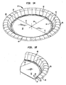
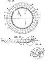
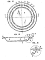
- FIG. 1A through 9 the present invention is illustrated in connection with several designs for disposable paper plates made from paperboard blanks and pressed in a heated die set as described hereinafter.
- a disposable paper plate 10 having a characteristic diameter D generally includes a bottom generally planar portion 12 , a first annular transition portion 14 , a sidewall portion 16 as well as a second annular transition portion 18 .
- the sidewall has a generally linear profile 20 between the first annular transition portion 14 and the second annular transition portion 18 .
- the inclined profile defines an angle of inclination A1 with respect to a vertical 24 of from about 10 to about 40°.
- An outer arcuate flange portion 26 has an upper convex surface 28 and defines an outer radius of curvature R3 .
- the ratio of the outer radius of curvature R3 of the outer arcuate flange portion to the characteristic diameter of the plate is generally from about 0.0175 to about 0.1.
- the angle of inclination A1 of sidewall 16 about its linear portion 20 with respect to a vertical 24 is typically from about 10 to about 40° and preferably from about 25 to about 30°.
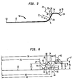
- Linear portion 20 of sidewall 16 extends over a length 21 from point A to point B along the sidewall as shown on Figure 5 between the outermost part of transition section 14 and the innermost portion of transition section 18 .
- Outer arcuate flange portion 26 typically extends downwardly with respect to the second annular transition portion 18 as will be appreciated particularly from Figures 3B and 6 . In most embodiments, the outer arcuate flange portion terminates well below the height of the uppermost portions of second annular transition portion 18 as can be seen in Figures 5 and 6 in particular and defines a flange outer vertical drop as discussed hereafter.
- the container is usually configured so that the outer radius of curvature R3 is defined by an outer arcuate flange portion 26 over an included angle A2 of from about 30° to about 80°.
- included angle A2 is from about 50° to about 75° or so.
- first annular transition portion 14 defines a concave upper surface 36 defining an inner radius of curvature R1 .
- the ratio of the inner radius of curvature to the characteristic diameter of the disposable container is generally from about 0.014 to about 0.14.
- the second annular transition portion typically defines a convex upper surface 38 defining an intermediate radius of curvature R2 .
- the ratio of the intermediate radius of curvature to the characteristic diameter of the disposable food container is generally from about 0.014 to about 0.07.
- the containers of the invention are pleated paperboard containers, being provided with a plurality of pleats such as pleats 40 about their entire periphery, extending from slightly above bottom portion 12 to the outer periphery of arcuate flange portion 26 as is shown in Figures 1 and following.
- pressed paperboard containers of the invention are prepared from scored paperboard blanks.
- the containers of the invention may be plates, bowls, platters, deep dish containers and so forth.
- the ratio of the height of the container Y5 to the diameter of the plate, D is from about 0.06 to about 0.12.
- plates of the invention may or may not include an inner flange portion 34 .
- an inner flange portion connecting the outer arcuate flange to the second annular transition portion of the container is provided, it characteristically defines a radial span 44 therebetween.
- the radial span of the inner flange portion is the horizontal distance between the end of the second annular transition portion and the beginning of the outer arcuate flange portion. This distance is shown as X3-X2 in Figure 6.
- the ratio of the radial span to the characteristic diameter of the container is from 0 to about 0.1.
- the inner flange portion may be horizontal over its radial span or may be inclined upwardly or downwardly, typically by +/- 10 degrees or less with respect to a horizontal line parallel to the bottom of the container.
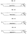
- FIG. 2 a schematic diagram comparing the profiles of various nominally 9 inch disposable plates.
- Figure 2A there is shown the profile of a plate configured generally in accordance with United States Patent No. 5,326,020 to Cheshire et al .
- This plate as can be seen from the diagram is characterized by way of an inner profile 46 extending from its center point at the left of the diagram through its second transition portion.
- This inner profile has a relatively steep generally straight upwardly and outwardly extending sidewall.
- Figure 2D a schematic diagram illustrating the profile from center of a nominally 9 inch plate configured generally in accordance with the teachings of United States Patent No. 5,088,640 to Littlejohn. It can be seen from the diagram here, that the profile includes an outer arcuate profile 48 which has a shape corresponding to the outer arcuate flange 26 of a container configured to the present invention.
- Figure 2B shows a profile of a container of the present invention wherein the container has an inner profile 46 resembling the inner profile of the prior art plate of Figure 2A, an outer profile 48 resembling the outer profile of a container configured in accordance with the United States Patent No. 5,088,640 to Littlejohn as well as an optional transition region 34 over a radial span 44.
- Figure 2C shows a profile of another container of the present invention wherein the container has an inner profile 46 resembling the inner profile of the container of Figure 2A and an outer profile 48 resembling the outer profile of the container of Figure 2D .
- the characteristic diameter, D, is twice X4 for circular containers such as plates.
- Table 1 Dimensions appearing in Table 1 and given below for various embodiments are those that are measured from the die side, that is the lower surface of the product, unless otherwise indicated.
- the numbers provided are based on forming die dimensions. It should be appreciated that for many products such as pressed paperboard products or thermoformed plastic products, the dimensions of the product may vary slightly from the die dimensions due to relaxation after forming, for example, a radius of curvature of a portion of the container may increase after forming and the corresponding included angle may decrease slightly. Intra-product variances may exist due to, for example, off-center forming. In such cases, average or mean values are used to characterize the container.
- a preferred technique is to measure a value such as flange outer vertical drop every ninety degrees, that is, at 0, 90°, 180° and 270° about the periphery of a container and then take the arithmetic average in order to determine the flange outer vertical drop of the container. Such averaging is also generally applied to included angles and curvatures of a container in order to determine the characteristic values thereof.
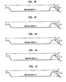
- Figure 4 various profiles for containers of the present invention.
- Invention Profile 1 which is generally the profile of the plate of Figure 1 and is shown in Figures 2B and 3B as well as Figures 5 and 6 .
- Figure 4B an alternate profile, Invention Profile 2 which differs slightly from that of Figure 4A in that there is no radial span between the second annular transition region and outer arcuate flange.
- Figures 4C-4I show still yet other profiles of the containers of the present invention having a generally linear sidewall and an arcuate outer flange as discussed hereinafter.
- the products of the invention are characterized by a generally linear sidewall profile, an arcuate outer flange portion of a specified curvature, as well as a flange outer vertical drop, illustrated on Figures 4A through 4I.
- the height H' of the downturn is the difference between the overall height of the container H and the height H" of the outermost peripheral portion of the container.
- Figures 5 and 6 there is shown in more detail the profile of the inventive container of Figures 1A and following.
- Figure 5 there is shown in schematic cross section a portion 50 of a plate extending outwardly from its center 52 to its outermost periphery 54 .
- the plate includes generally planar bottom portion 12 , sidewall portion 16 with its inclined generally linear profile 20 between the annular transition portions 14 and 18 as has been described hereinabove.
- the profile of Figure 5 is shown schematically in Figure 6 wherein the various parts and dimensions are labeled. Here again dimensions are generally given for the "die side” or lower surface of a plate manufactured in a press.
- bottom portion 12 is generally planar, it may have a step contour ("gravy ring") or a crown of a few degrees or so. As is known in the art, such features help prevent the container from "rocking" when placed on a surface.
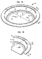
- FIGS 7A through 9 various illustrations of a disposable container in accordance with the present invention having the shape designated Invention Profile 9 in Figure 4I .
- the container of Figures 7A through 9 may be a thermoformed plate, for example, made from polystyrene or the like.
- the article is not a pleated article as was shown above in connection with Figures 1 and following.
- Pleated paperboard containers having generally the shape shown in Figure 7A and following may advantageously be made in accordance with the present invention; however, the geometry of the configuration of the present invention likewise has benefits for disposable plastic articles as will be appreciated from the stiffness and rigidity data appearing below.
- FIGS 7A through 9 a disposable food container in the form of a plate 10 having a characteristic diameter D which simply corresponds to the diameter of the plate since the plate is generally circular.
- the plate has a generally planar bottom portion 12 , a first annular transition portion 14 and a sidewall portion 16 .
- a secondary transition annular portion 18 extends between sidewall portion 16 and the arcuate outer flange 26 as before.
- the sidewall defines a generally linear profile 20 between annular transition portion 14 and annular transition portion 18 .
- the inclined generally linear profile portion 20 defines an angle of inclination A1 with a vertical 24 .
- Outer arcuate flange portion 26 has a convex upper surface 28 and defines an outer radius of curvature R3 as was discussed above in connection with the embodiment shown in Figures 1 and following.
- the outer radius of curvature is defined by portion 26 over an included angle A2.
- the various dimensions for the embodiment of Figures 7A through 9 are typically like those shown and discussed in connection with Figures 1 , 5 and 6 .
- a notable difference is however, that is that there is no transition portion 34 between annular transition portion 18 and the outer arcuate flange.
- X2 is equal to X3 such that the profile transitions directly to the outer arcuate flange.
- the dimensions of the embodiment of Invention Profile 9 of articles incorporating Invention Profile 9 is generally that described above. Note that here again the profile 50 extends from the center 52 to the outermost portion 54 as can be appreciated from Figure 8.
- X4 corresponds generally to the radius from center to the outer periphery of the plate
- X1 corresponds to the radius of the bottom of the plate, that is the radius of the serving or cutting area of the container
- Y1 corresponds to the height of the origin of inner radius of curvature
- R1 above the bottom of the plate
- X2 is the radius from the center of the plate to the beginning of inner flange portion 34
- X3 is the radius from the center of the plate to the end of the inner flange portion 34
- R1 is the radius of curvature of the first annular transition portion 14
- A1 is the sidewall angle defined between the linear portion 20 of the sidewall and a vertical 24
- R2 is the intermediate radius of curvature, the origin of which is a height Y2 above the bottom of the container
- R3 is the radius of curvature of arcuate outer flange portion 26 .
- Y3 is the height above the bottom of the container of the origin of the radius R3 (labeled 56 on Figure 6 ), A2 is the included angle of the arc defined by the outer arcuate flange portion 26 having radius of curvature, R3 , Y4 is the height above the bottom of the container of the outermost periphery 54 of arcuate outer flange portion 26 and Y5 is the overall height of the product.
- Typical ratios or shape factors are conveniently based on the characteristic diameter of the product, that is, twice X4 for a circular product.
- the ratio of the flange outer vertical drop to the characteristic diameter is generally greater than about 0.01. This quantity may be calculated by taking the difference between Y5 , the overall height, and Y4 , the height above the container bottom of the outermost periphery 54 of outer arcuate flange portion 26 and dividing by the characteristic diameter of the container.
- This quantity is determined by measuring Y4 and Y5 at four equally spaced locations for averaging purposes as noted above by positioning a container on a measurement table flange down and placing a lightweight (150 gram) plate preferably generally matching the shape of the bottom of the container thereon.
- the container is thus positioned so that its flange is lightly pressed against the flat measurement surface and a height gauge can be used to measure Y4 and Y5 in order to calculate the flange outer vertical drop.
- Any other suitable technique may be used so long as the measurement apparatus does not distort the shape of the container. For example, one could measure the overall height from the bottom surface to uppermost surface of the container and adjust for caliper.
- the arcuate outer flange of containers of the present invention is characterized by a smooth, flowing profile as described and illustrated herein. That profile may define a single radius of curvature such as R3 in Figure 6 for arcuate outer profiles of constant curvature.
- a weighted mean curvature may be used, the radius of curvature being the reciprocal of curvature.
- Such geometry may arise, for example, when the container is formed in a die set having a contour corresponding to the outer arcuate flange of the container with a single radius of curvature in that region and the product, after forming, relaxes slightly in some areas more than others.
- a somewhat segmented arcuate outer flange is employed, one may simply approximate the corresponding arcuate shape to determine the mean curvature (which may be a weighted mean curvature as noted above).
- the arcuate outer flange may optionally be adjacent an inner flange portion with a linear or straight profile as is seen in Figures 5 and 6 .
- the arcuate outer flange may optionally be adjacent an outer lip portion with a linear profile so long as the flowing arcuate outer profile having a radius of curvature of from about 0.0175 to about 0.1 times the characteristic diameter of the product is provided.
- the inner flange portion and/or an optional outer linear lip portion are not included in calculating the radius of curvature of the arcuate outer flange portion.
- the curvature of the arc of the arcuate outer flange may be a constant curvature; that is, having a single radius of curvature such as R3 in Figure 6 wherein the curvature of the arcuate outer flange is 1/R3 or the arc may have a mean curvature.
- the curvature of any arc of the container may be so characterized.
- the (dimensionless) product of the curvature of the arcuate outer flange portion and the characteristic diameter is generally from about 10 to about 50.
- the product of the characteristic diameter with the curvature of the arcuate outer flange is typically from about 15 to about 30 and perhaps in some preferred embodiments between about 20 and 30. From about 22.5 to 25 is particularly preferred in connection with some paperboard plate designs.
- the flowing outer profile is particularly important for forming the containers of the invention from paperboard in a heated die set, so that severe transitions involving two large relatively straight profile sections and a relatively small radius profile portion therebetween making a sharp corner on the outer part of the die and product profile are avoided.
- Such severe transitions in the outer flange profile as are seen, for example, in United States Patent No. 5,326,020, can make manufacturing difficult in terms of pleating control (especially for lower basis weight paperboards) and off-center forming problems.
- a first comparative series of nominally 9" plates having the configuration of U.S. Patent No. 5,088,640 were also prepared and tested.
- the plates were also prepared from scored and unscored paperboard of various basis weights and are designated Comparative Examples A through D in Tables 5 and 8.
- Patent No. 5,088,640 Comparative Examples A-D Example Paperboard Scoring A 163lb/rm Yes B 163lb/rm No C 206lb/rm No D 206lb/rm Yes Deflection (Inches) Load GM (grams) Load GM (grams) Load GM (grams) Load GM (grams) 0.0 0.0 0.0 0.0 0.0 0.1 34.0 39.8 57.7 59.3 0.2 66.7 80.3 127.5 122.8 0.3 95.4 112.8 195.0 181.9 0.4 119.0 142.0 250.8 230.4 0.5 138.1 167.1 293.7 269.1 0.6 154.0 187.4 328.9 299.9 0.7 167.3 205.4 359.2 329.3 0.8 178.4 220.6 387.8 350.7 0.9 187.8 ---- 417.0 373.8 1.0 200.0 ---- ---- ---- Instron® Rigidity for Nominally 9" Plates 163 lb
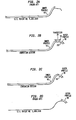
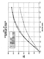
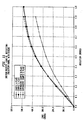
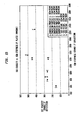
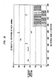
- Figures 10-13 are plots of load in grams versus deflection in inches for the Invention Profile 1 design and the prior art designs for various weights and for products prepared from paperboard blanks with and without scoring.
- the plates of the invention exhibit overall rigidity, as measured by either the SSI method or the Instron® method, comparable to the overall rigidity of containers configured in accordance with United states Patent No. 5,326,020.
- Rim stiffness is a measure of the local rim strength about the periphery of the container as opposed to overall or SSI rigidity. This test has been noted to correlate somewhat better with actual consumers' perception of product sturdiness.
- SSI rigidity is a measure of the load carrying capability of the plate, whereas rim stiffness relates to what a consumer feels when flexing a plate to gauge its strength.
- specimens are conditioned and testing performed at standard conditions for paperboard testing when a paper container is tested, 72°F and 50% relative humidity. Geometric averages for the machine direction and cross-direction are preferably reported.
- a rim stiffness instrument developed by Georgia-Pacific Corporation, Neenah Technical Center, 1915 Marathon Avenue, Neenah, Wisconsin 54956.
- This instrument includes a dial micrometer which reads to 0.001 inch available from Standard Gage Co., Inc., 70 Parker Avenue, Poughkeepsie, New York 12601, as well as a load gauge available from Chatillon, Force Measurements Division, P.O. Box 35668, Greensboro, NC 27425-5688.
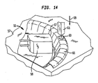
- the test procedure measures the force to deflect the rim downwardly 0.1 inch as the specimen is restrained about its bottom between a platen and a restraining member as will be further appreciated by reference to Figure 14 .
- Rim stiffness instrument 55 includes generally a platen 57 , a plurality of restraining members, preferably four equally spaced restraining members such as member 59 and a gauge 61 provided with a probe 63 .
- a specimen such as plate 65 is positioned as shown and clamped tightly about its planar bottom portion to platen 57 by way of restraining members, such as member 59 . The specimen is clamped over an area of several square inches or so such that the bottom of the specimen is fully restrained inwardly from the first transition portion.
- restraining member 59 is disposed such that its outer edge 67 is positioned at the periphery of the serving area of the container, that is, at X1 , the radius of the bottom of the container as shown in the various diagrams.
- Probe 63 is then advanced downwardly in the direction of arrow 69 a distance of 0.1 inch while the force is measured and recorded by gauge 61. Only the maximum force is recorded, typically occurring at the maximum deflection of 0.1 inch.
- Probe 63 is preferably positioned in the center of the flange of plate 65 or on a high point of the flange as appropriate.
- the end of the probe may be disk-shaped or of other suitable shape and is preferably mounted on a universal-type joint so that contact with the rim is maintained during testing.
- Probe 63 is generally radially aligned with restraining clamp member 59.
- the 170 lb basis weight plates of Invention Profile 9 and those of United States Patent Nos. 5,236,020 as well as 5,088,640 were evaluated in expert panel testing for overall performance, sturdiness, being easy to eat from, suitability for use with hot foods, suitability for use with greasy foods, durability through entire meal and ease of holding.
- the plates were fabricated from the same paperboard and thus differed only as to their configuration. Products were rated in each category on a scale of 1-9; 1 being extremely poor performance and 9 indicating the product performed extremely well. Results are summarized in Figure 17 .
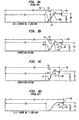
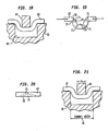
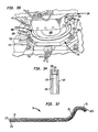
- FIG 18 there is shown a portion of paperboard stock 62 positioned between a score rule 64 and a scoring counter 66 provided with a channel 68 as would be the case in a scoring press or scoring portion of a pressware forming press.
- the geometry is such that when the press proceeds reciprocally downwardly and scores blank 62 , U-shaped score 70 results. At least incipient delamination of the paperboard into lamellae indicated at 77 , 79 , 81 is believed to occur in the sharp comer regions indicated at 71 in Figure 19 .
- the same reciprocal scoring operation could be performed in a separate press operation to create blanks that are fed and formed subsequently. Alternatively, a rotary scoring and blanking operation may be utilized as is known in the art.
- a U-shaped pleat 72 with a plurality of lamellae of rebonded paperboard along the pleat in the product is formed such that pleats 72 (or 40 as shown in Figure 1 ) generally have such configuration.
- the structure of pleat 72 is preferably as shown schematically in Figure 20 .
- the pleat has a thickness generally equal to the circumferentially adjacent areas of the rim and most preferably is more dense than adjacent areas.
- Integrated structures of rebonded lamellae are indicated schematically at 73 , 75 in Figure 20 on either side of paperboard fold lines in the pleat indicated in dashed lines.
- the substantially rebonded portion or portions of the pleats 72 in the finished product preferably extend generally over the entire length (75% or more) of the score which was present in the blank from which the product was made.
- the rebonded portion of the pleats may extend only over portions of the pleats in an annular region of the periphery of the article in order to impart strength.
- Such an annular region or regions may extend, for example, around the container extending approximately from the transition of the bottom of the container to the sidewall outwardly to the outer edge of the container, that is, generally along the entire length of the pleats shown in Figures 1A-1E .
- the rebonded structures may extend over an annular region which is less than the entire profile from the bottom of the container to its outer edge.
- an annular region of rebonded structures oriented in a radial direction may extend around the container from inner transition 14 to outermost edge 54 .
- an annular region or regions of such rebonded structures may extend over all or only a portion of length 21 of sidewall 16 ; over all or part of second annular transition portion 18 ; over all or part of outer arcuate flange portion 26 ; over all or part of flange region 34 ; or combinations thereof.
- the substantially integrated rebonded fibrous structures formed extend over at least a portion of the length of the pleat, more preferably over at least 50% of the length of the pleat and most preferably over at least 75% of the length of the pleat. Substantially equivalent rebonding can also occur when pleats are formed from unscored paperboard.
- At least one of the sidewall portion, the second annular transition portion, the optional inner flange portion and the arcuate outer flange portion and, if present, the optional inner flange portion is provided with a plurality of circumferentially spaced, radially extending regions formed from a plurality of paperboard lamellae rebonded into substantially integrated fibrous structures generally inseparable into their constituent lamellae.
- the rebonded structures extend around an annular region corresponding to a part of the profile of the sidewall, second annular transition portion, the optional inner flange portion or the arcuate outer flange portion of the container. More preferably, the integrated structures extend over at least part of all of the aforesaid profile regions about the periphery of the container.
- the integrated rebonded structures extend generally over the length of the pleats, over at least 75% of their length, for instance; however, so long as a majority of the pleats, more than about 50% for example, include the rebonded structures described herein over at least a portion of their length, a substantial benefit is realized.
- the rebonded structures define an annular rebonded array of integrated rebonded structures along the same part of the profile of the container around an annular region of the container.
- the rebonded structures could extend along the sidewall portion of all of pleats 40 shown in Figures 1A-1E along length 21 shown in Figure 5 to define an annular array around the sidewall portion of the container.
- rule 64 typically has a width 74 of 0.028 inches
- scoring channel 68 has a width 76 equal to the score rule width 74 plus 2 paperboard thicknesses and a clearance which may be 0.005 inches or may be from about 0 to about 0.01 inches.
- the scores thus formed in the paperboard blank have a width roughly corresponding to the width of the score rule that created them.
- the product of the invention is advantageously formed with a heated matched pressware die set utilizing inertial rotating pin blank stops as described in co-pending application United States Serial No. 09/653,577, filed August 31, 2000.
- the springs upon which the lower die half is mounted are typically constructed such that the full stroke of the upper die results in a force applied between the dies of from about 6000 to 8000 pounds. Similar forming pressures and control thereof may likewise be accomplished using hydraulics as will be appreciated by one of skill in the art.
- the paperboard which is formed into the blanks is conventionally produced by a wet laid paper making process and is typically available in the form of a continuous web on a roll.
- the paperboard stock is preferred to have a basis weight in the range of from about 100 pounds to about 400 pounds per 3000 square foot ream and a thickness or caliper in the range of from about 0.010 to about 0.040 inches as noted above. Lower basis weight paperboard is preferred for ease of forming and to save on feedstock costs.
- Paperboard stock utilized for forming paper plates is typically formed from bleached pulp furnish, and is usually double clay coated on one side. Such paperboard stock commonly has a moisture (water content) varying from about 4.0 to about 8.0 percent by weight.
- the effect of the compressive forces at the rim is greatest when the proper moisture conditions are maintained within the paperboard: at least 8% and less than 12% water by weight, and preferably 9.0 to 10.5%.
- Paperboard having moisture in this range has sufficient moisture to deform under pressure, but not such excessive moisture that water vapor interferes with the forming operation or that the paperboard is too weak to withstand the high compressive forces applied.
- the paperboard is treated by spraying or rolling on a moistening solution, primarily water, although other components such as lubricants may be added.
- the moisture content may be monitored with an in-line meter or with a hand held capacitive type moisture meter to verify that the desired moisture conditions are being maintained. It is preferred that the plate stock not be formed for at least six hours after moistening to allow the moisture within the paperboard to reach equilibrium.
- the paperboard stock is typically impregnated with starch and coated on one side with a liquid proof layer or layers comprising a press-applied, water-based coating applied over the inorganic pigment typically applied to the board during manufacturing.
- a liquid proof layer or layers comprising a press-applied, water-based coating applied over the inorganic pigment typically applied to the board during manufacturing.
- the paperboard stock is often initially printed before being coated.
- a first layer of latex coating may be applied over the printed paperboard with a second layer of acrylic coating applied over the first layer.
- These coatings may be applied either using the conventional printing press used to apply the decorative printing or may be applied using some other form of a conventional press coater.
- Preferred coatings utilized in connection with the invention may include 2 pigment (clay) containing layers, with a binder, of 3 lbs/3000 ft 2 ream or so followed by 2 acrylic layers of about 0.5-1 lbs/3000 ft 2 ream.
- the layers are applied by press coating methods, i.e., gravure, coil coating, flexographic methods and so forth as opposed to extrusion or film laminating methods which are expensive and may require off-line processing as well as large amounts of coating material.
- An extruded film for example, may require 25 lbs/3000 ft 2 ream.
- Carboxylated styrene-butadiene resins may be used with or without filler if so desired.
- a layer comprising a latex may contain any suitable latex known to the art.
- suitable latexes include styrene-acrylic copolymer, acrylonitrile styrene-acrylic copolymer, polyvinyl alcohol polymer, acrylic acid polymer, ethylene vinyl alcohol copolymer, ethylene-vinyl chloride copolymer, ethylene vinyl acetate copolymer, vinyl acetate acrylic copolymer, styrene-butadiene copolymer and acetate ethylene copolymer.
- the layer comprising a latex contains styrene-acrylic copolymer, styrene-butadiene copolymer, or vinyl acetate-acrylic copolymer. More preferably, the layer comprising a latex contains vinyl acetate ethylene copolymer.
- a commercially available vinyl acetate ethylene copolymer is "AIRFLEX® 100 HS" latex.
- "AIRFLEX® 100 HS” is a registered trademark of Air Products and Chemicals, Inc.)
- the layer comprising a latex contains a latex that is pigmented. Pigmenting the latex increases the coat weight of the layer comprising a latex thus reducing runnability problems when using blade cutters to coat the substrate.
- Pigmenting the latex also improves the resulting quality of print that may be applied to the coated paperboard.
- Suitable pigments or fillers include kaolin clay, delaminated clays, structured clays, calcined clays, alumina, silica, aluminosilicates, talc, calcium sulfate, ground calcium carbonates, and precipitated calcium carbonates.
- Other suitable pigments are disclosed, for example, in Kirk-Othmer, Encyclopedia of Chemical Technology, Third Edition, Vol. 17, pp. 798, 799, 815, 831-836, which is incorporated herein by reference.
- the pigment is selected from the group consisting of kaolin clay and conventional delaminated coating clay.
- An available delaminated coating clay is 'HYDRAPRINT" slurry, supplied as a dispersion with a slurry solids content of about 68%.
- "HYDRAPRINT” slurry is a trademark of Huber.
- the layer comprising a latex may also contain other additives that are well known in the art to enhance the properties of coated paperboard.
- suitable additives include dispersants, lubricants, defoamers, film-formers, antifoamers and crosslinkers.
- DISPEX N-40 is one suitable organic dispersant and comprises a 40% solids dispersion of sodium polycarboxylate.
- DISPEX N-40 is a trademark of Allied Colloids.
- “BERCHEM 4095” is one suitable lubricant and comprises 100% active coating lubricant based on modified glycerides.
- "BERCHEM 4095” is a trademark of Bercap.
- “Foamaster DF-177NS” is one suitable defoamer.
- “Foamaster DF-122 NS” is a trademark of Henkel.
- the coating comprises multiple layers that each comprise a latex.
- the stock is moistened on the uncoated side after all of the printing and coating steps have been completed.
- the web of paperboard stock is fed continuously from a roll through a scoring and cutting die to form the blanks which are scored and cut before being fed into position between the upper and lower die halves.
- the die halves are heated as described above, to aid in the forming process. It has been found that best results are obtained if the upper die half and lower die half - particularly the surfaces thereof- are maintained at a temperature in the range of from about 250°F to about 400°F, and most preferably at about 325°F ⁇ 25°F. These die temperatures have been found to facilitate the plastic deformation of paperboard in the rim areas if the paperboard has the preferred moisture levels.
- the amount of heat applied to the blank is sufficient to liberate the moisture within the blank and thereby facilitate the deformation of the fibers without overheating the blank and causing blisters from liberation of steam or scorching the blank material. It is apparent that the amount of heat applied to the paperboard will vary with the amount of time that the dies dwell in a position pressing the paperboard together.
- the preferred die temperatures are based on the usual dwell times encountered for normal production speeds of 30 to 60 pressings a minute, and commensurately higher or lower temperatures in the dies would generally be required for higher or lower production speeds, respectively.
- a die set wherein the upper assembly includes a segmented punch member and is also provided with a contoured upper pressure ring is advantageously employed in carrying out the present invention.
- Pleating control is achieved by lightly clamping the paperboard blank about a substantial portion of its outer portion as the blank is pulled into the die set and the pleats are formed. It is important during this process to avoid sharp comers about the outer flange because interaction of sharp features of the die with the paperboard blank may result in off-center forming.
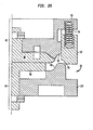
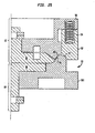
- One such apparatus is illustrated schematically in Figures 22-26 .
- FIG. 22-26 There is shown in schematic profile in Figures 22-26 a segmented matched die set 80 including a punch 82 as well as a die 84 .
- Punch 82 is provided with an articulated knock-out 86 , a punch forming contour 88 , a punch base 90 as well as a pressure ring 92 .
- a non-articulated knock-out could be used without a spring pre-load. Non-articulated knock-outs are those which do not extend to the container sidewall forming area.
- Pressure ring 92 is mounted for reciprocating relative motion with respect to the other portions of the punch and is biased downwardly toward die 84 by way of springs such as spring 94 .
- Spring preload is provided by means of several L-shaped brackets that are attached to the pressure ring around its perimeter and contact milled out regions in the punch base.
- the pressure ring is provided with a forming contour 95 as shown.
- Die 84 includes a die knock-out 96 and a die base 100 provided with a die forming contour 98 .
- Figures 22-26 show sequentially the movement of a die set during forming.
- the die set is fully open as would be the case as a blank is positioned in the die set for forming.
- the die set has advanced such that a blank is gripped between knock-outs 86 and 96 .
- a blank is clamped lightly between contour 95 of pressure ring 92 and die 84 .
- the punch and die continue to advance towards one another as the product is pressed into shape and pleats are formed in the paperboard between the various portions of the die set.
- Figure 26 a position where punch 82 and die 84 are fully advanced to conform the blank into the product shape.
- articulated punch knock-out 86 pushes product off of punch forming contour 88 and pressure ring 92 pushes the product out of the punch; preferably with air assist.
- Alternative tools suitable for making pressed paperboard disposable containers of the invention include a segmented matched die set with an upper pressure ring having a portion of the product profile and a lower draw ring that are allowed to translate during the formation process as controlled by springs with specified spring rates (lbs/in) deflection and preloads.
- the rings and springs are chosen so as to allow clamping of the blank against the tooling during the formation process allowing a greater distance and time during the forming operation for pleating control. This technique has been employed for years in connection with containers configured in accordance with United States Patent No. 5,088,640 noted above.
- the upper pressure ring springs, spring rates and preloads are sized so that the total force to deflect them from their initial preload state is approximately the same or slightly greater than the full deflection force of the opposing draw ring springs, such that the draw ring springs are ideally fully deflected before the pressure ring springs begin to compress.
- a relief area may exist on the lower draw ring to reduce the initial clamping force on the paper blank.
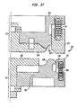
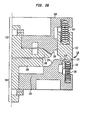
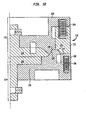
- a die set 110 including both an upper pressure ring and a lower draw ring is illustrated in schematic profile and forming sequence in Figures 27-32 .
- Die set 110 includes a punch 112 and a die 114 .
- Punch 112 is provided with an articulated knock-out 116 and defines a punch contour 118 .
- a non-articulated knock-out could be used as noted above.
- Pressure ring 122 is mounted for reciprocating relative motion with respect to the other portions of the punch and is biased downwardly toward die 114 by way of springs such as spring 124 .
- Spring preload is provided by means of several L-shaped brackets that are attached to the pressure ring around its perimeter and contact milled out regions in the punch base.
- the pressure ring is provided with a forming contour 125 .
- Die 114 includes a die knock-out 126 , a die base 130 provided with a forming contour 128 .
- There is additionally a draw ring 132 which is provided with a relieved surface portion 134 as shown in the various figures.
- Draw ring 132 is mounted for relative reciprocating motion with respect to die base 130 and is upwardly biased by springs such as spring 136 .
- Spring preload is provided by means of several L-shaped brackets that are attached to the draw ring around its perimeter and contact milled out regions in the base.
- Die set 110 operates in much the same way as die set 80 except that the draw ring and pressure ring engage the blank early in the forming process, illustrated sequentially in Figures 22-27 .
- Figure 27 shows die set 110 in an open position for receiving a blank to be formed.
- the die halves advance and pressure ring 122 and draw ring 132 engage the blank.
- the punch and die further advance so that a blank being formed is gripped between the pressure and draw ring as well as knock-outs 116 , 126 .
- the blank is clamped lightly between contour 125 of pressure ring 122 and die 114 . The process continues as is shown in Figures 31 and 32 . Upon opening to remove the product, staging is reversed.
- Any suitable apparatus and components thereof may be employed in connection with a forming process for a paperboard blank to produce the containers of the present invention.
- Draw and/or pressure rings may include one or more of the features: circular or other shape designed to match product shape; external location with respect to the forming die or punch base and die or base contour; stops (rigid or rotating) connected thereto, with an optional adjustment system, to locate the blank prior to formation; cut-out "relief" area that is approximately the same depth as the paperboard caliper to provide a reduced clamp force before pleating starts to occur; this provides initial pleating control before arcuate outer area contacts and provides final pleating control, the draw ring technique is preferred, believed to provide advantages over the no draw ring option; 3 to 4 L-shaped brackets each (stops) are bolted into both the draw and pressure rings around their perimeters and contact milled-out areas in the respective die and punch forming bases or contours to provide the springs with preload distances and forces; typical metal for the draw ring is steel, preferably AISI 1018, typical surface finishes of 125 rms are standard for the draw ring, 63 rms are desired for the horizontal top
- a metal die set 138 including an upper die set assembly 140 , commonly referred to as a punch and a lower die set assembly 142 commonly referred to as a die. That is, assembly 142 includes a die base 144 , a segmented die member 146 with a knock-out 148 , a sidewall forming section 150 , a rim forming portion 152 and a draw ring 154 . It will be appreciated that metal die set 138 is ordinarily operated in an inclined state in accordance with the following United States Patents, the disclosures of which have been incorporated by reference into this application:
- An important feature is a plurality of freely rotating stop pins 156 , 158 , 160 and 162 which may be constructed as shown in Figure 34 .
- Inner pins 158 , 160 are optionally mounted on L-shaped, pivotally mounted plates so that their position may be readily adjusted.
- outer pins 156, 162 may be positioned to act as guides so that a paperboard blank rests exclusively on pins 158, 160 when in proper position for forming.
- Each pin 156-162 is constructed of steel or other suitable material and includes an elongated shaft 164 as well as a central bore 166 .
- the bolt 170 is recessed within the cavity so that it will not interfere with operation of the apparatus.
- Bolts preferably socket head shoulder bolts, are used to secure pins 156-162 to draw ring 154 of segmented die 146 as shown in Figure 28.
- the bolts in central bore 166 are close in size to the bore diameter to prevent chatter and horizontal movement of the rotating pin blank stops but enough clearance is preferably allowed so that pins 156 - 162 are freely rotating about their retaining bolts. If so desired, a slight tension or bias can be provided to damp the motion of rotating pin blank stops 156 - 162 , particularly when very heavy stock is employed in the forming process.
- Blank 172 in the process of being supplied to die set 138 .
- Blank 172 is provided with a plurality of scores 70 which are subsequently formed into pleats in the final product. That is to say, paperboard is gathered and pressed into pleats 72 ( Figure 36 ) about scores 70 .
- Any suitable score pattern may be employed and the pleats preferably are formed with substantially integrated fibrous structures including rebonded lamellae as noted above.
- the rotating pin blank stops 156-162 are located on the forward portion of lower die assembly 142 , that is, the downstream production portion of the die, such that a gravity fed blank, such as blank 172 , will contact the blank stops as it is fed to the die set.
- the rear, outer pins may be spaced slightly further apart so that they operate as guides and do not contact the blank when it is positioned for forming.
- blank stops 156 and 162 are in opposing relationship at the periphery of the lower die at a distance which is less than the maximum transverse dimension of the blank, in this case the diameter of blank 172 since it is a circular blank and that pins 158 and 160 are also located in opposing relationship at a distance which is also less than the diameter of the blank inasmuch as the plate will move in the direction indicated generally by arrows 174 in the production process, it is important that the rotating pin blank stops do not interfere with the motion of the finished product.
- the top assembly 140 is lowered and the forming process is carried out in a conventional manner and the product is formed as shown in Figure 36.
- the distances between the outer pin blank stops 156, 162 is such that the finished product will readily slide between these pins, i.e., the distance is greater than or equal to the diameter of the finished container.
- the product will travel over pins 158 and 160 which are typically of the same or lower height than pins 156 and 162 and are closer together than the maximum diameter of the finished container.
- the disposable containers of the present invention may be made of multilayer laminates with one or more paperboard layers. Some embodiments may include embossed layers to increase strength and/or insulative properties.
- FIG 37 there is shown schematically a container 10 of the invention formed from a composite paperboard material wherein the containers are formed by laminating separate layers 175, 177 and 179 to one another in the form of the container having the shape shown in Figure 1 .
- the particular manipulative steps of forming the plate of Figure 37 are discussed in greater detail in United States Patents Nos. 6,039,682, 6,186,394 and 6,287,247, the disclosures of which are incorporated herein by reference.
- the disposable containers of the present invention may likewise be formed of a thermoplastic material. Suitable forming techniques include injection molding, injection blow molding, injection stretch molding and composite injection molding. Foamed material may be used if so desired.
- the containers may be thermoformed, thermoformed by the application of vacuum or thermoformed by a combination of vacuum and pressure.
- the thermoplastic material may be a foamed or solid polymeric material selected from the group consisting of: polyamides, polyacrylates, polysulfones, polyetherketones, polycarbonates, acrylics, polyphenylene sulfides, acetals, cellulosic polymers, polyetherimides, polyphenylene ethers or oxides, styrene-maleic anhydride copolymers, styrene-acrylonitrile copolymers, polyvinylchlorides and mixtures thereof.
- a preferred thermoplastic material comprises a foamed or solid polymeric material selected from the group consisting of: polyesters, polystyrenes, polypropylenes, polyethylenes and mixtures thereof.
- the container is made from a mineral-filled polypropylene sheet.
- the article may be made having a wall thickness from about 10 to about 80 mils and consists essentially of from about 40 to about 90 percent by weight of a polypropylene polymer, from about 10 to about 60 percent by weight of a mineral filler, from about 1 to about 15 percent by weight polyethylene, up to about 5 weight percent titanium dioxide and optionally including a basic organic or inorganic compound comprising the reaction product of an alkali metal or alkaline earth element with carbonates, phosphates, carboxylic acids as well as alkali metal and alkaline earth element oxides, hydroxides, or silicates and basic metal oxides, including mixtures of silicon dioxide with one or more of the following oxides: magnesium oxide, calcium oxide, barium oxide, and mixtures thereof.
- a preferred wall thickness for plastic containers is from about 10 to about 50 mils; from about 15 to about 25 mils being typical. Mica is often a suitable filler.
- thermoforming is usually a preferred method of making the containers of the present invention from thermoplastic compositions.
- thermoforming is the draping of a softened sheet over a shaped mold.
- thermoforming is the automatic high speed positioning of a sheet having an accurately controlled temperature into a pneumatically actuated forming station whereby the article's shape is defined by the mold, followed by trimming and regrind collection as is well known in the art.
- Still other alternative arrangements include the use of drape, vacuum, pressure, free blowing, matched die, billow drape, vacuum snap-back, billow vacuum, plug assist vacuum, reverse draw with plug assist, pressure bubble immersion, trapped sheet, slip, diaphragm, twin-sheet cut sheet, twin-sheet roll-fed forming or any suitable combinations of the above. Details are provided in J.L. Throne's book, Thermoforming , published in 1987 by Coulthard. Pages 21 through 29 of that book are incorporated herein by reference. Suitable alternate arrangements also include a pillow forming technique which creates a positive air pressure between two heat softened sheets to inflate them against a clamped male/female mold system to produce a hollow product.
- Metal molds are etched with patterns ranging from fine to coarse in order to simulate a natural or grain like texturized look. Suitable formed articles are trimmed in line with a cutting die and regrind is optionally reused since the material is thermoplastic in nature. Other arrangements for productivity enhancements include the simultaneous forming of multiple articles with multiple dies in order to maximize throughput and minimize scrap.
- the containers of the present invention may be produced utilizing polymeric compositions filled with conventional inorganic fillers such as talc, mica, wollastonite and the like, wherein the polymer component is, for example, a polyester, a polystyrene homopolymer or copolymer, a polyolefin or one or more of the polymers noted above.
- polypropylene polymers which are suitable are preferably selected from the group consisting of isotactic polypropylene, and copolymers of propylene and ethylene wherein the ethylene moiety is less than about 10% of the units making up the polymer, and mixtures thereof.
- such polymers have a melt flow index from about 0.3 to about 4, but most preferably the polymer is isotactic polypropylene with a melt-flow index of about 1.5.
- the melt-compounded composition from which the articles are made may include polypropylene and optionally further includes a polyethylene component and titanium dioxide.
- a polyethylene polymer or component may be any suitable polyethylene such as HDPE, LDPE, MDPE, LLDPE or mixtures thereof and may be melt-blended with polypropylene if so desired.
- HDPE high density polyethylene which is substantially linear and has a density of generally greater that 0.94 up to about 0.97 g/cc.
- LDPE low density polyethylene which is characterized by relatively long chain branching and a density of about 0.912 to about 0.925 g/cc.
- LLDPE or linear low density polyethylene is characterized by short chain branching and a density of from about 0.92 to about 0.94 g/cc.
- MDPE intermediate density polyethylene
- the primary mineral filler is mica, talc, kaolin, bentonite, wollastonite, milled glass fiber, glass beads (solid or hollow), silica, or silicon carbide whiskers or mixtures thereof.
- Polypropylene may be melt-compounded with acidic-type minerals such as mica, as well as inorganic materials and/or basic materials such as calcium carbonate, talc, barium sulfate, calcium sulfate, magnesium sulfate, clays, glass, dolomite, alumina, ceramics, silica, pigments such as titanium dioxide based pigments and so on. Many of these materials are enumerated in the Encyclopedia of Materials Science and Engineering, Vol. # 3, pp. 1745 - 1759, MIT Press, Cambridge, MA (1986), the disclosure of which is incorporated herein by reference. Combinations of fillers are preferred in some embodiments.
Landscapes
- Engineering & Computer Science (AREA)
- Food Science & Technology (AREA)
- Containers Having Bodies Formed In One Piece (AREA)
- Packages (AREA)
- Table Devices Or Equipment (AREA)
- Cartons (AREA)
Applications Claiming Priority (4)
| Application Number | Priority Date | Filing Date | Title |
|---|---|---|---|
| US35118602P | 2002-01-23 | 2002-01-23 | |
| US351186P | 2002-01-23 | ||
| US348278P | 2003-01-21 | ||
| US10/348,278 US6715630B2 (en) | 2002-01-23 | 2003-01-21 | Disposable food container with a linear sidewall profile and an arcuate outer flange |
Publications (2)
| Publication Number | Publication Date |
|---|---|
| EP1332972A2 true EP1332972A2 (fr) | 2003-08-06 |
| EP1332972A3 EP1332972A3 (fr) | 2004-08-25 |
Family
ID=27668993
Family Applications (1)
| Application Number | Title | Priority Date | Filing Date |
|---|---|---|---|
| EP03250423A Withdrawn EP1332972A3 (fr) | 2002-01-23 | 2003-01-23 | Vaisselle jetable à paroi latérale linéaire et bride extérieure courbée |
Country Status (3)
| Country | Link |
|---|---|
| US (1) | US6715630B2 (fr) |
| EP (1) | EP1332972A3 (fr) |
| CA (1) | CA2416972C (fr) |
Cited By (12)
| Publication number | Priority date | Publication date | Assignee | Title |
|---|---|---|---|---|
| WO2008049048A3 (fr) * | 2006-10-18 | 2008-07-24 | Graphic Packaging Int Inc | Outil pour former un article ou un récipient en trois dimensions |
| US8124201B2 (en) | 2006-03-10 | 2012-02-28 | Graphic Packaging International, Inc. | Injection-molded composite construct |
| US8444902B2 (en) | 2002-03-15 | 2013-05-21 | Graphic Packaging International, Inc. | Container having a rim or other feature encapsulated by or formed from injection-molded material |
| US8464894B2 (en) | 2007-12-28 | 2013-06-18 | Graphic Packaging International, Inc. | Injection-molded composite construct and tool for forming construct |
| US8464871B2 (en) | 2009-09-14 | 2013-06-18 | Graphic Packaging International, Inc. | Blank and forming tool for forming a container |
| US8480551B2 (en) | 2009-06-17 | 2013-07-09 | Graphic Packaging International, Inc. | Tool for forming a three dimensional container or construct |
| US8678986B2 (en) | 2009-12-30 | 2014-03-25 | Graphic Packaging International, Inc. | Method for positioning and operating upon a construct |
| US8777010B2 (en) | 2009-08-26 | 2014-07-15 | Graphic Packaging International, Inc. | Container blank and container with denesting feature |
| US11084626B2 (en) | 2015-02-27 | 2021-08-10 | Graphie Packaging International, LLC | Method of forming a container |
| CN113906226A (zh) * | 2019-06-03 | 2022-01-07 | 圣戈班性能塑料帕姆普斯有限公司 | 凸缘轴承、组件及其制作方法 |
| EP4116075A2 (fr) * | 2021-07-07 | 2023-01-11 | Brown LLC | Procédés et systèmes de production d'articles pressés |
| WO2023212613A1 (fr) * | 2022-04-26 | 2023-11-02 | Hoffmaster Group, Inc. | Produits en carton dotés d'une rigidité et de propriétés de barrière à l'humidité améliorées |
Families Citing this family (70)
| Publication number | Priority date | Publication date | Assignee | Title |
|---|---|---|---|---|
| US8651366B2 (en) | 2009-03-27 | 2014-02-18 | Dixie Consumer Products Llc | Rigid-buckling-resistant-fluted paperboard container with arcuate outer region |
| USD496825S1 (en) | 2002-10-21 | 2004-10-05 | Solo Cup Company | Ergonomic disposable plate handle |
| USD576840S1 (en) | 2002-10-22 | 2008-09-16 | Pactiv Corporation | Bowl |
| USD514880S1 (en) * | 2002-10-22 | 2006-02-14 | Pactiv Corporation | Container |
| USD525083S1 (en) * | 2002-10-22 | 2006-07-18 | Pactiv Corporation | Container |
| USD552424S1 (en) | 2002-10-22 | 2007-10-09 | Pactiv Corporation | Container |
| USD527584S1 (en) * | 2002-10-22 | 2006-09-05 | Pactiv Corporation | Bowl |
| USD546621S1 (en) | 2002-10-22 | 2007-07-17 | Pactiv Corporation | Ribs pattern for container |
| JP2005041509A (ja) * | 2003-07-25 | 2005-02-17 | Konica Minolta Medical & Graphic Inc | トレー容器の製造方法及びトレー容器 |
| US8584929B2 (en) | 2003-10-20 | 2013-11-19 | Dixie Consumer Products Llc | Pressed paperboard servingware with improved rigidity and rim stiffness |
| TWM252665U (en) * | 2004-02-10 | 2004-12-11 | Shi-Ching Jang | Integrally formed paper-made meal case with multiple grids |
| US7819790B2 (en) * | 2004-02-20 | 2010-10-26 | Dixie Consumer Products Llc | Apparatus for making paperboard pressware with controlled blank feed |
| USD520303S1 (en) * | 2004-06-18 | 2006-05-09 | Pactiv Corporation | Container |
| USD526163S1 (en) | 2004-06-18 | 2006-08-08 | Pactiv Corporation | Bowl |
| USD545134S1 (en) | 2004-06-18 | 2007-06-26 | Pactiv Corporation | Bowl |
| USD525487S1 (en) | 2004-06-18 | 2006-07-25 | Pactiv Corporation | Container |
| USD547616S1 (en) * | 2004-06-18 | 2007-07-31 | Pactiv Corporation | Container |
| USD528867S1 (en) * | 2004-06-18 | 2006-09-26 | Pactiv Corporation | Container |
| USD525832S1 (en) | 2004-06-18 | 2006-08-01 | Pactiv Corporation | Container |
| USD533031S1 (en) * | 2004-06-18 | 2006-12-05 | Pactiv Corporation | Bowl |
| USD526853S1 (en) * | 2004-07-28 | 2006-08-22 | Pactiv Corporation | Container |
| USD540121S1 (en) * | 2004-12-14 | 2007-04-10 | Dixie Consumer Products Llc | Dodecagonal three compartment serving plate |
| USD533406S1 (en) | 2004-12-14 | 2006-12-12 | Fort James Corporation | Oval three compartmented serving plate |
| USD532656S1 (en) | 2004-12-14 | 2006-11-28 | Fort James Corporation | Oval two compartmented serving plate |
| USD541589S1 (en) * | 2004-12-14 | 2007-05-01 | Dixie Consumer Products Llc | Octagonal three compartment plate |
| USD526852S1 (en) | 2005-02-15 | 2006-08-22 | Fort James Corporation | Round plate with concentric compartment and two side compartments |
| USD526536S1 (en) | 2005-02-15 | 2006-08-15 | Fort James Corporation | Round plate with concentric compartment |
| US7578234B2 (en) * | 2005-03-23 | 2009-08-25 | Wallace Maurice Sumner | Method of making and using a kitchen receptacle for the collection and transfer of food material |
| US7419462B1 (en) * | 2005-06-13 | 2008-09-02 | Dixie Consumer Products Llc | Pressware die set with pneumatic blank feed |
| US8430660B2 (en) * | 2005-08-19 | 2013-04-30 | Dixie Consumer Products Llc | Pressware forming apparatus, components therefore and methods of making pressware therefrom |
| US8047834B2 (en) * | 2005-08-19 | 2011-11-01 | Dixie Consumer Products Llc | Segmented pressware die set with anti-twist guide keys |
| US8734309B2 (en) * | 2005-08-19 | 2014-05-27 | Dixie Consumer Products Llc | Forming die assembly with enhanced stop |
| US9555916B2 (en) * | 2006-01-13 | 2017-01-31 | Solo Cup Operating Corporation | Paperboard container having increased rigidity and method of manufacturing thereof |
| USD559036S1 (en) | 2006-02-07 | 2008-01-08 | Pactiv Corporation | Set of ribs for container |
| US20080011758A1 (en) * | 2006-07-14 | 2008-01-17 | Phillip John Campbell | Folding combination food plate/tray and storage container |
| US9555594B2 (en) | 2006-07-17 | 2017-01-31 | Dixie Consumer Products Llc | Disposable fluted paperboard plates and method of making same |
| USD564138S1 (en) | 2007-01-10 | 2008-03-11 | Dunn Steven B | Pet feeding bowl insert |
| US8177119B2 (en) * | 2007-11-01 | 2012-05-15 | Dixie Consumer Products Llc | Pressed paperboard servingware with arched bottom panel and sharp brim transition |
| US7980450B2 (en) * | 2008-01-04 | 2011-07-19 | Dixie Consumer Products Llc | Disposable pressware prepared from wax-infused paperboard |
| US7975871B2 (en) | 2008-04-04 | 2011-07-12 | Graphic Packaging International, Inc. | Container with injection-molded feature and tool for forming container |
| US8474689B2 (en) | 2008-12-15 | 2013-07-02 | Dixie Consumer Products Llc | Method for in-die lamination of plural layers of material and paper-containing product made thereby |
| USD610665S1 (en) | 2009-01-30 | 2010-02-23 | Sinochem Ningbo Ltd. | Fire bowl |
| US8388335B2 (en) * | 2011-01-18 | 2013-03-05 | Dixie Consumer Products Llc | Blank containment device and methods |
| US8684260B2 (en) | 2011-04-01 | 2014-04-01 | Reynolds Consumer Products Inc. | Paperboard plate with corner walls |
| JP2013082109A (ja) * | 2011-10-07 | 2013-05-09 | Toyo Seikan Kaisha Ltd | しわ発生の少ない紙成形体とその製造方法 |
| US9481777B2 (en) | 2012-03-30 | 2016-11-01 | The Procter & Gamble Company | Method of dewatering in a continuous high internal phase emulsion foam forming process |
| BR112015007977B1 (pt) | 2012-10-17 | 2021-08-03 | Graphic Packaging International, Llc | Recipiente para acondicionar um artigo, blanqueta para formar um recipiente para acondicionar um artigo, e método para formar um recipiente |
| US20150048089A1 (en) * | 2013-08-13 | 2015-02-19 | Huhtamaki, Inc. | Container Lid with Plastic Ring and Method of Manufacture |
| CA2940303C (fr) | 2015-09-08 | 2023-08-01 | Dixie Consumer Products Llc | Assiette en carton presse a bord large et solidite amelioree |
| USD791545S1 (en) * | 2015-09-11 | 2017-07-11 | Yu-Nien Li | Circular container |
| US10602862B2 (en) | 2016-03-03 | 2020-03-31 | Michael Lawrence Serpa | Secure-grip disposable dish for food |
| USD823645S1 (en) | 2016-06-06 | 2018-07-24 | Reynolds Consumer Products LLC | Plate |
| USD823644S1 (en) | 2016-06-06 | 2018-07-24 | Reynolds Consumer Products LLC | Plate |
| USD818319S1 (en) | 2016-08-17 | 2018-05-22 | Reynolds Consumer Products LLC | Plate |
| USD845716S1 (en) * | 2016-09-19 | 2019-04-16 | Gittit Hagoel Segev | Plate |
| ES1225984Y (es) * | 2019-01-18 | 2019-05-28 | Copy Valls Con Gelats S L | Cubierto de carton |
| US11535417B2 (en) * | 2019-01-22 | 2022-12-27 | Peerless Machine & Tool Corporation | Meat tray |
| KR102068694B1 (ko) * | 2019-09-27 | 2020-01-21 | 주식회사 신우 | 종이 재질의 포장용 완충 트레이의 제조방법 및 이에 의해 제조되는 완충 트레이 |
| AU2020391456A1 (en) | 2019-11-26 | 2022-06-16 | Westrock Mwv, Llc | Reinforced paperboard tray, method for manufacturing a reinforced paperboard tray, and method for using a paperboard tray |
| IT202000002533A1 (it) * | 2020-02-10 | 2021-08-10 | T M E S P A | Metodo e macchina confezionatrice per la realizzazione di una cialda compostabile per prodotti da infusione |
| US12016474B2 (en) | 2021-07-09 | 2024-06-25 | Gpcp Ip Holdings Llc | Pressed paperboard bowl with wide upper rim |
| EP4377213B1 (fr) * | 2021-07-30 | 2025-08-06 | Société des Produits Nestlé S.A. | Systeme et procédé pour former une dosette compostable pour boissons a partir d'une feuille ayant un niveau d'humidité contrôlée |
| CN117693473A (zh) * | 2021-07-30 | 2024-03-12 | 雀巢产品有限公司 | 用于由具有受控水分含量的片材形成饮料用可堆肥囊包的系统和方法 |
| US12344414B2 (en) | 2021-07-30 | 2025-07-01 | Societe Des Produits Nestle S.A. | Manufacturing line for manufacturing a compostable pod for brewing products and system for measuring and regulating the relative humidity of a biodegradable paper-based material |
| WO2023017302A1 (fr) * | 2021-08-13 | 2023-02-16 | Boegli-Gravures Sa | Procédé et outil pour gaufrer un papier protecteur |
| CN114261143A (zh) * | 2021-11-30 | 2022-04-01 | 江苏鑫城包装科技有限公司 | 一种酒盒包装用衬纸压泡刮棱装置 |
| US20230276968A1 (en) | 2022-03-04 | 2023-09-07 | Gpcp Ip Holdings Llc | Rigid compartmented pressware plate with tall dividers |
| MX2024004110A (es) | 2023-04-03 | 2024-11-08 | Dart Container | Contenedor de cartón con características de pared lateral que proporcionan una mayor rigidez y método de fabricación del mismo |
| US12304691B1 (en) | 2023-11-03 | 2025-05-20 | Pressed Paperboard Technologies, LLC | Food tray |
| USD1133765S1 (en) * | 2024-05-29 | 2026-07-14 | Crown Display Inc. | Paper plate |
Citations (36)
| Publication number | Priority date | Publication date | Assignee | Title |
|---|---|---|---|---|
| US2911320A (en) | 1956-05-28 | 1959-11-03 | British Cellophane Ltd | Production of moistureproof sheet wrapping materials |
| US3963843A (en) | 1972-12-20 | 1976-06-15 | Domtar Limited | Production of coated paper |
| US4078924A (en) | 1976-09-13 | 1978-03-14 | Xerox Corporation | Imaging surface smoothing with roughened nickel foil |
| US4238533A (en) | 1976-04-16 | 1980-12-09 | La Cellophane | Coating process and apparatus |
| US4503096A (en) | 1983-09-08 | 1985-03-05 | Ytong Ag | Method and device for the continuous application of a reinforcement layer onto a porous mineral building board |
| US4567099A (en) | 1984-12-21 | 1986-01-28 | The Dow Chemical Company | High solids latexes for paper coatings |
| US4588539A (en) | 1985-02-04 | 1986-05-13 | James River Corporation Of Virginia | Process and press with a controlled pressure system |
| US4609704A (en) | 1984-06-22 | 1986-09-02 | Air Products And Chemicals, Inc. | Vinyl acetate/acrylate copolymer emulsions for paper coating compositions |
| US4609140A (en) | 1982-04-13 | 1986-09-02 | James River - Dixie Northern Inc. | Rigid paperboard container and method and apparatus for producing same |
| US4721500A (en) | 1982-04-13 | 1988-01-26 | James River-Dixie Northern, Inc. | Method of forming a rigid paper-board container |
| US4832676A (en) | 1986-12-08 | 1989-05-23 | James River-Norwalk, Inc. | Method and apparatus for forming paperboard containers |
| US4898752A (en) | 1988-03-30 | 1990-02-06 | Westvaco Corporation | Method for making coated and printed packaging material on a printing press |
| US4948635A (en) | 1985-09-06 | 1990-08-14 | Yasui Seiki Co., Ltd. | Gravure coating device and method |
| US4997682A (en) | 1989-07-06 | 1991-03-05 | Protein Technologies International, Inc. | Paper coating composition |
| US5033373A (en) | 1988-05-06 | 1991-07-23 | Eduard Kusters Maschinenfabrik Gmbh & Co. Kg | Apparatus and process for producing a smooth and glossy surface on a paper web |
| US5049420A (en) | 1989-02-23 | 1991-09-17 | The Wiggins Teape Group Limited | Process for applying microcapsule-containing compositions to paper |
| US5088640A (en) | 1991-09-06 | 1992-02-18 | James River Corporation Of Virginia | Rigid four radii rim paper plate |
| US5169715A (en) | 1989-04-10 | 1992-12-08 | Societe Anonyme: Aussedat-Rey | High gloss base paper |
| US5249946A (en) | 1991-03-08 | 1993-10-05 | James River Corporation Of Virginia | Plate forming die set |
| US5326020A (en) | 1992-09-01 | 1994-07-05 | James River Corporation Of America | Rigid paperboard container |
| US5334449A (en) | 1990-09-18 | 1994-08-02 | Stora Feldmuhle Aktiengesellschaft | Coated paper |
| US5340611A (en) | 1989-07-25 | 1994-08-23 | J. M. Voith Gmbh | Process for coating travelling webs |
| US5603886A (en) | 1990-12-27 | 1997-02-18 | Tokai Kogyo Kk | Process of making a panel unit |
| US5609686A (en) | 1995-08-30 | 1997-03-11 | Minnesota Mining And Manufacturing Company | Flexible adjustable smoothing blade |
| US5770303A (en) | 1994-07-06 | 1998-06-23 | Gencorp Inc. | Occluded composite-particle latex |
| US5776619A (en) | 1996-07-31 | 1998-07-07 | Fort James Corporation | Plate stock |
| US5795928A (en) | 1994-11-03 | 1998-08-18 | Hercules Incorporated | Cellulose ethers in emulsion polymerization dispersions |
| US5852166A (en) | 1992-10-02 | 1998-12-22 | Cargill, Incorporated | Paper having a melt-stable lactide polymer coating and process for manufacture thereof |
| US5869567A (en) | 1996-03-08 | 1999-02-09 | Unitika Ltd. | Polyester resin aqueous dispersion and process for preparing the same |
| US5932651A (en) | 1995-11-02 | 1999-08-03 | Dow Corning Corporation | Silicone/organic copolymer emulsions |
| US5972167A (en) | 1993-11-16 | 1999-10-26 | Nippon Paper Industries Co., Ltd. | Transfer roll coating color and a coated paper |
| US5981011A (en) | 1992-01-22 | 1999-11-09 | A*Ware Technologies, L.C. | Coated sheet material |
| US6039682A (en) | 1996-10-23 | 2000-03-21 | Fort James Corporation | Containers formed of a composite paperboard web and methods of forming |
| US6211501B1 (en) | 1998-03-20 | 2001-04-03 | Fort James Corporation | Thermoformed polypropylene mineral-filled microwaveable containers having food contact compatible olfactory properties and process for their manufacture |
| US6211500B1 (en) | 1998-03-20 | 2001-04-03 | Fort James Corporation | Disposable, microwaveable containers having suitable food contact compatible olfactory properties and process for their manufacture |
| US6474497B1 (en) | 1999-07-02 | 2002-11-05 | Fort James Corporation | Smooth profiled food service articles |
Family Cites Families (11)
| Publication number | Priority date | Publication date | Assignee | Title |
|---|---|---|---|---|
| US4721499C1 (en) | 1984-03-20 | 2002-06-04 | Fort James Corp | Method of producing a rigid paperboard container |
| AU572632B2 (en) | 1984-03-20 | 1988-05-12 | James River Corporation Of Virginia | Rigid paperboard container |
| US4781566A (en) | 1987-11-09 | 1988-11-01 | James River Corporation | Apparatus and related method for aligning irregular blanks relative to a die half |
| US5230939A (en) * | 1990-09-04 | 1993-07-27 | James River Corporation Of Virginia | Forming of pressed trays |
| US5203491A (en) | 1991-10-17 | 1993-04-20 | James River Corporation Of Virginia | Bake-in press-formed container |
| WO1993014642A1 (fr) | 1992-01-22 | 1993-08-05 | A*Ware Technologies, L.C. | Feuille enrobee et procede d'enrobage |
| US5830548A (en) | 1992-08-11 | 1998-11-03 | E. Khashoggi Industries, Llc | Articles of manufacture and methods for manufacturing laminate structures including inorganically filled sheets |
| US5938112A (en) * | 1995-08-28 | 1999-08-17 | Fort James Corporation | Rigid paperboard container |
| US6401962B1 (en) * | 1999-07-02 | 2002-06-11 | Fort James Corporation | Disposable food serving bowl |
| US6440509B1 (en) * | 1999-07-16 | 2002-08-27 | Fort James Corporation | Compartmented disposable plate with asymmetric rib geometry |
| US7048176B2 (en) * | 2000-10-27 | 2006-05-23 | Fort James Corporation | Deep dish disposable container |
-
2003
- 2003-01-21 US US10/348,278 patent/US6715630B2/en not_active Expired - Lifetime
- 2003-01-22 CA CA2416972A patent/CA2416972C/fr not_active Expired - Lifetime
- 2003-01-23 EP EP03250423A patent/EP1332972A3/fr not_active Withdrawn
Patent Citations (39)
| Publication number | Priority date | Publication date | Assignee | Title |
|---|---|---|---|---|
| US2911320A (en) | 1956-05-28 | 1959-11-03 | British Cellophane Ltd | Production of moistureproof sheet wrapping materials |
| US3963843A (en) | 1972-12-20 | 1976-06-15 | Domtar Limited | Production of coated paper |
| US4238533A (en) | 1976-04-16 | 1980-12-09 | La Cellophane | Coating process and apparatus |
| US4078924A (en) | 1976-09-13 | 1978-03-14 | Xerox Corporation | Imaging surface smoothing with roughened nickel foil |
| US4609140A (en) | 1982-04-13 | 1986-09-02 | James River - Dixie Northern Inc. | Rigid paperboard container and method and apparatus for producing same |
| US4721500A (en) | 1982-04-13 | 1988-01-26 | James River-Dixie Northern, Inc. | Method of forming a rigid paper-board container |
| US4609140C1 (en) | 1982-04-13 | 2002-04-16 | James River Corp | Rigid paperboard container and method and apparatus for producing same |
| US4503096A (en) | 1983-09-08 | 1985-03-05 | Ytong Ag | Method and device for the continuous application of a reinforcement layer onto a porous mineral building board |
| US4609704A (en) | 1984-06-22 | 1986-09-02 | Air Products And Chemicals, Inc. | Vinyl acetate/acrylate copolymer emulsions for paper coating compositions |
| US4567099A (en) | 1984-12-21 | 1986-01-28 | The Dow Chemical Company | High solids latexes for paper coatings |
| US4588539A (en) | 1985-02-04 | 1986-05-13 | James River Corporation Of Virginia | Process and press with a controlled pressure system |
| US4948635A (en) | 1985-09-06 | 1990-08-14 | Yasui Seiki Co., Ltd. | Gravure coating device and method |
| US4832676A (en) | 1986-12-08 | 1989-05-23 | James River-Norwalk, Inc. | Method and apparatus for forming paperboard containers |
| US4898752A (en) | 1988-03-30 | 1990-02-06 | Westvaco Corporation | Method for making coated and printed packaging material on a printing press |
| US5033373A (en) | 1988-05-06 | 1991-07-23 | Eduard Kusters Maschinenfabrik Gmbh & Co. Kg | Apparatus and process for producing a smooth and glossy surface on a paper web |
| US5049420A (en) | 1989-02-23 | 1991-09-17 | The Wiggins Teape Group Limited | Process for applying microcapsule-containing compositions to paper |
| US5169715A (en) | 1989-04-10 | 1992-12-08 | Societe Anonyme: Aussedat-Rey | High gloss base paper |
| US4997682A (en) | 1989-07-06 | 1991-03-05 | Protein Technologies International, Inc. | Paper coating composition |
| US5340611A (en) | 1989-07-25 | 1994-08-23 | J. M. Voith Gmbh | Process for coating travelling webs |
| US5334449A (en) | 1990-09-18 | 1994-08-02 | Stora Feldmuhle Aktiengesellschaft | Coated paper |
| US5603886A (en) | 1990-12-27 | 1997-02-18 | Tokai Kogyo Kk | Process of making a panel unit |
| US5249946A (en) | 1991-03-08 | 1993-10-05 | James River Corporation Of Virginia | Plate forming die set |
| US5088640A (en) | 1991-09-06 | 1992-02-18 | James River Corporation Of Virginia | Rigid four radii rim paper plate |
| US5981011A (en) | 1992-01-22 | 1999-11-09 | A*Ware Technologies, L.C. | Coated sheet material |
| US5326020A (en) | 1992-09-01 | 1994-07-05 | James River Corporation Of America | Rigid paperboard container |
| US5852166A (en) | 1992-10-02 | 1998-12-22 | Cargill, Incorporated | Paper having a melt-stable lactide polymer coating and process for manufacture thereof |
| US5972167A (en) | 1993-11-16 | 1999-10-26 | Nippon Paper Industries Co., Ltd. | Transfer roll coating color and a coated paper |
| US5770303A (en) | 1994-07-06 | 1998-06-23 | Gencorp Inc. | Occluded composite-particle latex |
| US5795928A (en) | 1994-11-03 | 1998-08-18 | Hercules Incorporated | Cellulose ethers in emulsion polymerization dispersions |
| US5609686A (en) | 1995-08-30 | 1997-03-11 | Minnesota Mining And Manufacturing Company | Flexible adjustable smoothing blade |
| US5932651A (en) | 1995-11-02 | 1999-08-03 | Dow Corning Corporation | Silicone/organic copolymer emulsions |
| US5869567A (en) | 1996-03-08 | 1999-02-09 | Unitika Ltd. | Polyester resin aqueous dispersion and process for preparing the same |
| US5776619A (en) | 1996-07-31 | 1998-07-07 | Fort James Corporation | Plate stock |
| US6039682A (en) | 1996-10-23 | 2000-03-21 | Fort James Corporation | Containers formed of a composite paperboard web and methods of forming |
| US6186394B1 (en) | 1996-10-23 | 2001-02-13 | Fort James Corporation | Containers formed of a composite paperboard web and methods of forming the same |
| US6287247B1 (en) | 1996-10-23 | 2001-09-11 | Fort James Corporation | Containers formed of a composite paperboard web and methods of forming the same |
| US6211501B1 (en) | 1998-03-20 | 2001-04-03 | Fort James Corporation | Thermoformed polypropylene mineral-filled microwaveable containers having food contact compatible olfactory properties and process for their manufacture |
| US6211500B1 (en) | 1998-03-20 | 2001-04-03 | Fort James Corporation | Disposable, microwaveable containers having suitable food contact compatible olfactory properties and process for their manufacture |
| US6474497B1 (en) | 1999-07-02 | 2002-11-05 | Fort James Corporation | Smooth profiled food service articles |
Cited By (27)
| Publication number | Priority date | Publication date | Assignee | Title |
|---|---|---|---|---|
| US8444902B2 (en) | 2002-03-15 | 2013-05-21 | Graphic Packaging International, Inc. | Container having a rim or other feature encapsulated by or formed from injection-molded material |
| US8529238B2 (en) | 2002-03-15 | 2013-09-10 | Graphic Packaging International, Inc. | Container having a rim or other feature encapsulated by or formed from injection-molded material |
| US8540111B2 (en) | 2002-03-15 | 2013-09-24 | Graphic Packaging International, Inc. | Container having a rim or other feature encapsulated by or formed from injection-molded material |
| US8784959B2 (en) | 2006-03-10 | 2014-07-22 | Graphic Packaging International, Inc. | Injection-molded composite construct |
| US8124201B2 (en) | 2006-03-10 | 2012-02-28 | Graphic Packaging International, Inc. | Injection-molded composite construct |
| US11472592B2 (en) | 2006-03-10 | 2022-10-18 | Graphic Packaging International, Llc | Injection-molded composite construct |
| US9850020B2 (en) | 2006-03-10 | 2017-12-26 | Graphic Packaging International, Inc. | Injection-molded composite construct |
| US9808117B2 (en) | 2006-10-18 | 2017-11-07 | Graphic Packaging International, Inc. | Tool for forming a three dimensional article or container |
| WO2008049048A3 (fr) * | 2006-10-18 | 2008-07-24 | Graphic Packaging Int Inc | Outil pour former un article ou un récipient en trois dimensions |
| US8801995B2 (en) | 2006-10-18 | 2014-08-12 | Graphic Packaging International, Inc. | Tool for forming a three dimensional article or container |
| US9517600B2 (en) | 2007-12-28 | 2016-12-13 | Graphic Packaging International, Inc. | Method for forming a container having an injection-molded feature |
| US10105884B2 (en) | 2007-12-28 | 2018-10-23 | Graphic Packaging International, Llc | Tool for forming an injection molded composite construct |
| US8464894B2 (en) | 2007-12-28 | 2013-06-18 | Graphic Packaging International, Inc. | Injection-molded composite construct and tool for forming construct |
| US9694553B2 (en) | 2009-06-17 | 2017-07-04 | Graphic Packaging International, Inc. | Tool for forming a three dimensional container or construct |
| US8480551B2 (en) | 2009-06-17 | 2013-07-09 | Graphic Packaging International, Inc. | Tool for forming a three dimensional container or construct |
| US8777010B2 (en) | 2009-08-26 | 2014-07-15 | Graphic Packaging International, Inc. | Container blank and container with denesting feature |
| US11554569B2 (en) | 2009-09-14 | 2023-01-17 | Graphic Packaging International, Llc | Blank and forming tool for forming a container |
| US8464871B2 (en) | 2009-09-14 | 2013-06-18 | Graphic Packaging International, Inc. | Blank and forming tool for forming a container |
| US10173386B2 (en) | 2009-09-14 | 2019-01-08 | Graphic Packaging International, Llc | Blank and forming tool for forming a container |
| US8678986B2 (en) | 2009-12-30 | 2014-03-25 | Graphic Packaging International, Inc. | Method for positioning and operating upon a construct |
| US11084626B2 (en) | 2015-02-27 | 2021-08-10 | Graphie Packaging International, LLC | Method of forming a container |
| CN113906226A (zh) * | 2019-06-03 | 2022-01-07 | 圣戈班性能塑料帕姆普斯有限公司 | 凸缘轴承、组件及其制作方法 |
| CN113906226B (zh) * | 2019-06-03 | 2023-12-12 | 圣戈班性能塑料帕姆普斯有限公司 | 凸缘轴承、组件及其制作方法 |
| EP4116075A2 (fr) * | 2021-07-07 | 2023-01-11 | Brown LLC | Procédés et systèmes de production d'articles pressés |
| US12515431B2 (en) | 2021-07-07 | 2026-01-06 | Brown Llc | Methods and systems for producing pressware |
| WO2023212613A1 (fr) * | 2022-04-26 | 2023-11-02 | Hoffmaster Group, Inc. | Produits en carton dotés d'une rigidité et de propriétés de barrière à l'humidité améliorées |
| US12281442B2 (en) | 2022-04-26 | 2025-04-22 | Hoffmaster Group, Inc. | Paperboard products with improved rigidity and moisture barrier properties |
Also Published As
| Publication number | Publication date |
|---|---|
| CA2416972C (fr) | 2010-02-23 |
| US20030173366A1 (en) | 2003-09-18 |
| EP1332972A3 (fr) | 2004-08-25 |
| CA2416972A1 (fr) | 2003-07-23 |
| US6715630B2 (en) | 2004-04-06 |
Similar Documents
| Publication | Publication Date | Title |
|---|---|---|
| US6715630B2 (en) | Disposable food container with a linear sidewall profile and an arcuate outer flange | |
| US7048176B2 (en) | Deep dish disposable container | |
| US8177119B2 (en) | Pressed paperboard servingware with arched bottom panel and sharp brim transition | |
| US9833088B2 (en) | Pressed paperboard servingware with improved rigidity and rim stiffness | |
| US7337943B2 (en) | Disposable servingware containers with flange tabs | |
| US8684260B2 (en) | Paperboard plate with corner walls | |
| US9655461B2 (en) | Pressware paperboard plate with wide brim and greater strength | |
| US9392891B2 (en) | Rigid-buckling-resistant-fluted paperboard container with arcuate outer region | |
| US8474689B2 (en) | Method for in-die lamination of plural layers of material and paper-containing product made thereby | |
| US20030034351A1 (en) | Crush-resistant disposable lid | |
| US7070729B2 (en) | Pressware die set with product ejectors at outer forming surfaces | |
| WO2023166415A1 (fr) | Plaque de pressage à compartimenté rigide avec diviseurs de hauteur |
Legal Events
| Date | Code | Title | Description |
|---|---|---|---|
| PUAI | Public reference made under article 153(3) epc to a published international application that has entered the european phase |
Free format text: ORIGINAL CODE: 0009012 |
|
| AK | Designated contracting states |
Designated state(s): AT BE BG CH CY CZ DE DK EE ES FI FR GB GR HU IE IT LI LU MC NL PT SE SI SK TR |
|
| AX | Request for extension of the european patent |
Extension state: AL LT LV MK RO |
|
| PUAL | Search report despatched |
Free format text: ORIGINAL CODE: 0009013 |
|
| AK | Designated contracting states |
Kind code of ref document: A3 Designated state(s): AT BE BG CH CY CZ DE DK EE ES FI FR GB GR HU IE IT LI LU MC NL PT SE SI SK TR |
|
| AX | Request for extension of the european patent |
Extension state: AL LT LV MK RO |
|
| RIC1 | Information provided on ipc code assigned before grant |
Ipc: 7B 65D 1/34 A Ipc: 7A 47G 19/03 B |
|
| 17P | Request for examination filed |
Effective date: 20050119 |
|
| AKX | Designation fees paid |
Designated state(s): AT BE BG CH CY CZ DE DK EE ES FI FR GB GR HU IE IT LI LU MC NL PT SE SI SK TR |
|
| RAP1 | Party data changed (applicant data changed or rights of an application transferred) |
Owner name: DIXIE CONSUMER PRODUCTS LLC |
|
| 17Q | First examination report despatched |
Effective date: 20070824 |
|
| RAP1 | Party data changed (applicant data changed or rights of an application transferred) |
Owner name: GPCP IP HOLDINGS LLC |
|
| STAA | Information on the status of an ep patent application or granted ep patent |
Free format text: STATUS: EXAMINATION IS IN PROGRESS |
|
| STAA | Information on the status of an ep patent application or granted ep patent |
Free format text: STATUS: THE APPLICATION IS DEEMED TO BE WITHDRAWN |
|
| 18D | Application deemed to be withdrawn |
Effective date: 20180801 |
|
| RIC1 | Information provided on ipc code assigned before grant |
Ipc: A47G 19/03 20060101ALI20030614BHEP Ipc: B65D 1/34 20060101AFI20040708BHEP |