EP1333145A2 - Eckverbinder für Verstärkungsmetallhohlprofile in Kunststoffhohlprofilen und ihre Montagevorrichtung - Google Patents
Eckverbinder für Verstärkungsmetallhohlprofile in Kunststoffhohlprofilen und ihre Montagevorrichtung Download PDFInfo
- Publication number
- EP1333145A2 EP1333145A2 EP02425721A EP02425721A EP1333145A2 EP 1333145 A2 EP1333145 A2 EP 1333145A2 EP 02425721 A EP02425721 A EP 02425721A EP 02425721 A EP02425721 A EP 02425721A EP 1333145 A2 EP1333145 A2 EP 1333145A2
- Authority
- EP
- European Patent Office
- Prior art keywords
- section bars
- square
- tubular section
- metallic
- heads
- Prior art date
- Legal status (The legal status is an assumption and is not a legal conclusion. Google has not performed a legal analysis and makes no representation as to the accuracy of the status listed.)
- Granted
Links
Images


Classifications
-
- E—FIXED CONSTRUCTIONS
- E06—DOORS, WINDOWS, SHUTTERS, OR ROLLER BLINDS IN GENERAL; LADDERS
- E06B—FIXED OR MOVABLE CLOSURES FOR OPENINGS IN BUILDINGS, VEHICLES, FENCES OR LIKE ENCLOSURES IN GENERAL, e.g. DOORS, WINDOWS, BLINDS, GATES
- E06B3/00—Window sashes, door leaves, or like elements for closing wall or like openings; Layout of fixed or moving closures, e.g. windows in wall or like openings; Features of rigidly-mounted outer frames relating to the mounting of wing frames
- E06B3/96—Corner joints or edge joints for windows, doors, or the like frames or wings
- E06B3/964—Corner joints or edge joints for windows, doors, or the like frames or wings using separate connection pieces, e.g. T-connection pieces
- E06B3/9645—Mitre joints
- E06B3/9646—Mitre joints using two similar connecting pieces each connected with one or the frame members and drawn together at the joint
-
- E—FIXED CONSTRUCTIONS
- E06—DOORS, WINDOWS, SHUTTERS, OR ROLLER BLINDS IN GENERAL; LADDERS
- E06B—FIXED OR MOVABLE CLOSURES FOR OPENINGS IN BUILDINGS, VEHICLES, FENCES OR LIKE ENCLOSURES IN GENERAL, e.g. DOORS, WINDOWS, BLINDS, GATES
- E06B3/00—Window sashes, door leaves, or like elements for closing wall or like openings; Layout of fixed or moving closures, e.g. windows in wall or like openings; Features of rigidly-mounted outer frames relating to the mounting of wing frames
- E06B3/04—Wing frames not characterised by the manner of movement
- E06B3/06—Single frames
- E06B3/08—Constructions depending on the use of specified materials
- E06B3/20—Constructions depending on the use of specified materials of plastics
- E06B3/22—Hollow frames
- E06B3/221—Hollow frames with the frame member having local reinforcements in some parts of its cross-section or with a filled cavity
- E06B3/222—Hollow frames with the frame member having local reinforcements in some parts of its cross-section or with a filled cavity with internal prefabricated reinforcing section members inserted after manufacturing of the hollow frame
-
- E—FIXED CONSTRUCTIONS
- E06—DOORS, WINDOWS, SHUTTERS, OR ROLLER BLINDS IN GENERAL; LADDERS
- E06B—FIXED OR MOVABLE CLOSURES FOR OPENINGS IN BUILDINGS, VEHICLES, FENCES OR LIKE ENCLOSURES IN GENERAL, e.g. DOORS, WINDOWS, BLINDS, GATES
- E06B3/00—Window sashes, door leaves, or like elements for closing wall or like openings; Layout of fixed or moving closures, e.g. windows in wall or like openings; Features of rigidly-mounted outer frames relating to the mounting of wing frames
- E06B3/96—Corner joints or edge joints for windows, doors, or the like frames or wings
- E06B3/9604—Welded or soldered joints
- E06B3/9608—Mitre joints
Definitions
- the present invention relates to the fabrication of plastic frames for windows and doors and in particular it concerns a square for the structural connection of metallic tubular section bars contained, for reinforcement purposes, inside plastic tubular section bars.
- the prior art provides for the use of extruded tubular section bars made of polyvinylchloride (PVC) which: are cut to measure; butted at the ends with an oblique cut, appropriately inclined, and permanently joined to each other by means of a head-to-head weld executed with localised thermal softening of the section bars, with their compression in mutual abutment and with the cooling and solidification of the junction area.
- PVC polyvinylchloride
- the frames thus formed are then subjected to milling operations to remove the projecting parts of the beads due to the plastic sliding of the softened material and determined by the upsetting that results from the mutual compression of the section bars.
- PVC section bars generally have fairly modest mechanical strength and rigidity, compared with the analogous characteristics of the metallic section bars employed to manufacture windows and doors. This can cause, under the different conditions of use of the frame, such distortions and expansions as to prevent the correct closure of the window or door and/or as to prevent the regular mobility of the mechanisms for operating the handles, the locks and the opening and closing devices with which the window or door is normally fitted.
- Tubular section bars made of steel have considerably smaller length than the members (uprights and cross members) of the frames that house them. Their length cannot be such as to reach the welded area of the plastic section bars, or it would be impossible for the machines that weld the plastic profiles to operate correctly.
- the welding machines use special welding blades which, by interposing themselves between the heads of the section bars to be connected, heat the their edges to be joined; and which then retract from the junction area to allow the section bar heads to be subsequently approached to each other and joined.
- junction areas of the frames of the windows and doors thereby obtained, lacking internal reinforcement, continue to be structurally critical for the entire window or door. Their critical nature is further enhanced by the fact that the weld notoriously modifies the crystal structure of the plastic material making it more fragile and more susceptible than others to undergo a more rapid structural degradation when the window or door is in use and by the fact that the metallic tubular elements on the other hand provide no contribution to the reduction of the drawbacks caused by this phenomenon.
- a known constructive technique provides for introducing connecting squares made of plastic material into the junction area of the section bars.
- These squares essentially comprise a pair of distinct connecting elements, having a body that can be coupled in prismatic fashion with the inner cavity of the metallic section bars in such a way as to be able to translate longitudinally therein, and having heads, monolithic with the body, so shaped as to project from an end of the tubular body and to be coupled in frontal abutment with each other and in lateral abutment with the walls of the plastic section bars.
- connection The strength of the connection is left, in this case as well, solely to the weld and this entails the persistence of all the drawbacks linked to the crystallisation, fragility and rapid deterioration phenomena that are typical of welded connections.
- the connecting elements even when using connecting means whereby the bodies of the connecting elements of the square are made to expand inside the cavity of the metallic tubular section bars in such a way as to obtain a sort of their anchorage by interference, the connecting elements always maintain a more or less accentuated freedom to slide relative to the metallic tubular element.
- the aim of the present invention is to overcome the aforementioned drawbacks by means of a metallic square that is able to connect the metallic tubular section bars in such a way as to allow to create after the weld of the plastic section bars and also inside their angular junction area, an uninterrupted metallic structure able to provide the window or door as a whole with the strength and rigidity required for its optimal functionality, independently from the strength and rigidity contribution offered by the external plastic section bars.
- a square for the structural connection of tubular metallic section bars contained for reinforcement purposes inside plastic tubular section bars mutually welded head to head comprising a pair of distinct connecting elements, having a body that is able to coupled in prismatic fashion with an inner cavity of the metallic section bars in such a way as to be able to be translated longitudinally therein and having heads, monolithic with the body, so shaped as to be able to couple in mutual abutment in correspondence with a junction plane and in abutment with walls of the plastic section bars, characterised in that said connecting elements are made of metallic material and have projections and cavities that are counter shaped in complementary fashion obtained in their heads and able mutually to fit inside each other according to a sense of travel of a transverse direction to the junction plane of the section bars; connecting means, able to be activated through a wall opening of the plastic section bars and after the welding of the plastic section bars, being provided to oppose the disengagement of the projections and of the cavities in the other sense of said
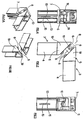
- the reference 1 globally indicates a square for the structural connection of metallic tubular section bars 2m, with quadrangular contour, contained for reinforcement purposes inside plastic tubular section bars 2p, preferably made of polyvinylchloride (PVC) and destined to be mutually welded head to head in forming angular connections of generic window or door frames.
- PVC polyvinylchloride
- the square 1 essentially comprises a pair of distinct connecting elements, indicated as 3, which are mutually connected by a screw 10 and which are then connected with the metallic section bars 2m and plastic section bars 2p of the window or door frame.
- the connecting elements 3, wholly metallic, comprise in particular a monolithic body 4 and a head 5.
- the body 4 has substantially quadrilateral contour and it is provided with a longitudinal groove 13 delimited by parallel bent edges 15, projecting from a lateral wall of the body 4.
- edges 15 are opposed to equidistant undulated faces whose curvilinear development is generated by envelopment lines of circle arcs complementary to the contour of screws for anchoring the square 1 to the metallic section bars 2m and plastic section bars 2p, indicated as 16.
- the body 4 is destined to be inserted in the internal cavity 7 of a corresponding metallic tubular section bar 2m and to be coupled in prismatic fashion therewith in such a way as to maintain the freedom to translate in guided fashion along a direction 17 substantially longitudinal to the section bar 2m that houses it.
- the heads 5 have quadrilateral contour defined by four plane squares 19, mutually orthogonal and having different superficial extension.
- the contour of the heads 5 has a greater extension than the corresponding contour of the body 4, so that when the body 4 is inserted in the cavity 7 of the metallic section bar 2m whereto it is destined, the heads 5 project totally outside the metallic section bar 2m.
- the quadrilateral contour of the heads 5 is instead strictly complementary to the interior contour of the inner cavities 18 of the plastic section bars 2p.
- the heads 5 can therefore be contained in said cavities 18 in centred conditions and with parallelism of their own peripheral faces 19 and of mutually opposite inner walls 20 of the plastic section bars 2p.
- the heads 5 are able to be coupled in abutment with the walls 20 of the plastic section bars 2 with the possibility to translate, longitudinally to the section bars 2p and in guided fashion along the walls 20, in the direction 17 of each of the section bars 2p constituting the members of the window or door.
- the heads 5 also have inclined faces 21, which can be associated in contact and in mutual opposition and are able to define an interposed junction plane 8 of the connecting elements 3 of the square 1; junction plane 8 that is preferably oriented according to the bisecting line of the angle of connection of two contiguous members of the window or door.
- the inclined faces 21 are also traversed by holes 11 [visible for instance in figure 6] having their axis substantially orthogonal to the junction plane 8.
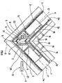
- Figures 2, 3, 4, 5A and 5B also show that the heads 5 are provided with projections 6 and cavities 7 counter-shaped in complementary fashion and alternatively positioned on the faces 21.
- the projections 6 and the cavities 7, which preferably have pyramid frustum shape, are such as to mutually fit into each other in orderly fashion when the heads 5 are approached to the junction plane 8, i.e. when the heads 5 are moved towards each other in accordance with one of the senses of travel of a direction 9 transverse to the junction plane 8 of the section bars 2m; 2p, direction 9 which practically coincides with the axis of the screw 10.
- Figure 6 also shows that one of the heads 5 is provided, in correspondence with its inclined inner face 22, with a blade 12 that protrudes from said head 5 and projects towards the hole 11 in such a way as to intercept the trajectory of translation of the screw 10 when the screw, associated with the heads 5, reaches a first, well determined, condition of tightening with the heads 5.
- the transition towards a condition of further tightening is enabled by the bending of the blade 12 or also by its shearing by the head 5.
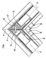
- Figures 9, 10, 11 and 12 show a different embodiment of the square 1 in which the bodies 4 of the connecting elements 3 lack the indented seat 13 and are instead provided with push-buttons 14 [also visible in figure 13] housed in a seat 23 of the body 4 and contrasted by a spring 24 that constantly thrusts them towards the exterior of the body 4.
- the connecting elements 3 of the square 1 are inserted, independently from each other, with their body 4 in the cavity 7 of the respective metallic section bars 2m and with the heads 5 projecting from said cavity 7 towards the junction plane 8.
- the screw 10 is then introduced, through a wall opening 26, obtained in the plastic section bars 2p, in the holes 11 of the two heads 5.
- the insertion of the screw 10 brings the heads 5 to be positioned automatically at the same distance from the junction plane 5, whatever their primitive position along the direction 17.
- the connecting screw 10 of the heads 5 is fully tightened against the resistance offered by the blade 12, which, behaving as a discriminator means between two different conditions of tightening of the screw 10, yields under the thrust of the screw 10 bending permanently or even detaching itself from the head 5.
- the full tightening of the screw 10, i.e. of the connecting means it embodies, leads to exerting on the metallic tubular section bars 2m opposing traction forces, bilateral to the junction plane, which mutually concur in the junction plane 8, i.e. in the vertex of the window or door frame.
- the square 1 enables not only the realisation, inside the junction area of the plastic section bars 2p, of the geometric conditions of perfect fit that assure the consequent geometric regularity of the window or door frame, but also the continuous structural connection of the various metallic tubular section bars 2m. This allows to recreate, inside the window or door, an actual strong metal frame that runs uninterruptedly along the entire contour of the window or door.
- the metallic frame thus formed provides the plastic window or door with adequate mechanical rigidity and strength for the most severe operating stresses of the window or door.
- the tensioning of the frame deriving from the full tightening of the screw 10 also allows considerably to reduce, if not totally to eliminate, the condition of internal stress on the head to head welds of the plastic tubular section bars 2p in correspondence with their permanent junction area whose material is more heavily tensioned. This allows ultimately to assure to the window or door the additional advantage of a longer duration of its working life.
Landscapes
- Engineering & Computer Science (AREA)
- Civil Engineering (AREA)
- Structural Engineering (AREA)
- Wing Frames And Configurations (AREA)
- Laminated Bodies (AREA)
- Lining Or Joining Of Plastics Or The Like (AREA)
- Joining Of Building Structures In Genera (AREA)
- Mutual Connection Of Rods And Tubes (AREA)
- Reinforcement Elements For Buildings (AREA)
Applications Claiming Priority (2)
| Application Number | Priority Date | Filing Date | Title |
|---|---|---|---|
| ITRN20020004 | 2002-01-31 | ||
| IT2002RN000004A ITRN20020004A1 (it) | 2002-01-31 | 2002-01-31 | Squadra per connessione strutturale, di profilati tubolari metallici contenuti per rinforzo internamente a profilati tubolari plastici e rel |
Publications (3)
| Publication Number | Publication Date |
|---|---|
| EP1333145A2 true EP1333145A2 (de) | 2003-08-06 |
| EP1333145A3 EP1333145A3 (de) | 2004-08-18 |
| EP1333145B1 EP1333145B1 (de) | 2008-10-29 |
Family
ID=11456720
Family Applications (1)
| Application Number | Title | Priority Date | Filing Date |
|---|---|---|---|
| EP02425721A Expired - Lifetime EP1333145B1 (de) | 2002-01-31 | 2002-11-25 | Eckverbinder für Verstärkungsmetallhohlprofile in Kunststoffhohlprofilen und ihre Montageverfahren |
Country Status (4)
| Country | Link |
|---|---|
| EP (1) | EP1333145B1 (de) |
| AT (1) | ATE412814T1 (de) |
| DE (1) | DE60229616D1 (de) |
| IT (1) | ITRN20020004A1 (de) |
Cited By (13)
| Publication number | Priority date | Publication date | Assignee | Title |
|---|---|---|---|---|
| WO2005019588A1 (de) | 2003-08-18 | 2005-03-03 | Forster Rohr- & Profiltechnik Ag | Eckverbindung und verfahren zum herstellen einer solchen eckverbindung |
| NL1027104C2 (nl) * | 2004-09-24 | 2006-03-27 | Vitalu Beheer B V | Werkwijze voor het onder een hoek onderling verbinden van holle kozijndelen. |
| DE102010062751A1 (de) * | 2010-12-09 | 2012-06-14 | Greiner Tool.Tec Gmbh | Eckverbindungsvorrichtung für Profile |
| CN103850597A (zh) * | 2012-12-06 | 2014-06-11 | 家居安全组有限公司 | 角部固定系统和方法 |
| CN103953267A (zh) * | 2014-04-22 | 2014-07-30 | 山东华信塑胶股份有限公司 | 一种塑钢窗框直角螺接连接结构及其安装方法 |
| DE102014116642A1 (de) * | 2014-11-13 | 2016-05-19 | Veka Ag | Verfahren zur In-Situ-Fertigung eines Eckverbinderelements in auf Gehrung geschnittenen Fenster- und Türprofilen und Eckverbinder-Fromelement dafür |
| CN106382083A (zh) * | 2016-11-29 | 2017-02-08 | 平湖信达电子塑业有限公司 | 一种转角铝材端盖 |
| GB2512911B (en) * | 2013-04-11 | 2018-11-14 | Hl Plastics Ltd | Improvements in or relating to bi-fold door assemblies |
| US10151138B2 (en) * | 2015-06-04 | 2018-12-11 | Jean Bourly | Window frame and/or opening frame |
| EP3511509A1 (de) * | 2018-01-12 | 2019-07-17 | Weber Glas en Kunststof B.V. | Verbindungskonstruktion mit schweissfrei verbundenen hohlkammerprofilen auf polymer-basis |
| GB2571912A (en) * | 2018-02-06 | 2019-09-18 | Thomas Investment Holdings Ltd | Connecting method |
| CN111119691A (zh) * | 2020-01-19 | 2020-05-08 | 中山市荣新五金塑料制品厂有限公司 | 一种窗框的连接结构 |
| DE102020121302A1 (de) | 2020-08-13 | 2022-02-17 | Heroal - Johann Henkenjohann Gmbh & Co. Kg | Vorrichtung zur Beschattung über Eck verlaufender Fenster- oder Türöffnungen |
Families Citing this family (2)
| Publication number | Priority date | Publication date | Assignee | Title |
|---|---|---|---|---|
| CN107060595A (zh) * | 2017-05-04 | 2017-08-18 | 四川良木道门窗型材有限公司 | 一种无缝整焊窗 |
| DE102020108412A1 (de) * | 2020-03-26 | 2021-09-30 | Aluplast Gmbh | Extrudiertes Fenster- oder Tür-Hohlkammerprofil, System mit einem solchen Hohlkammerprofil und daraus hergestellter Rahmen |
Family Cites Families (4)
| Publication number | Priority date | Publication date | Assignee | Title |
|---|---|---|---|---|
| DE2112112A1 (de) * | 1971-03-13 | 1972-09-21 | Heinz Pasche | Vorrichtung zur Eckverbindung von Rahmen mit als Hohlprofil ausgefuehrten Rahmenelementen |
| LU64936A1 (de) * | 1971-04-01 | 1972-07-07 | ||
| DE8513805U1 (de) * | 1985-05-09 | 1988-03-31 | Thyssen Plastik Anger KG, 8000 München | Eckverbinder |
| EP1172511A1 (de) * | 2000-07-10 | 2002-01-16 | L.M. dei F.lli Monticelli S.r.l. | Verbindungselement für Hohlprofile und Verfahren zum montieren |
-
2002
- 2002-01-31 IT IT2002RN000004A patent/ITRN20020004A1/it unknown
- 2002-11-25 AT AT02425721T patent/ATE412814T1/de not_active IP Right Cessation
- 2002-11-25 EP EP02425721A patent/EP1333145B1/de not_active Expired - Lifetime
- 2002-11-25 DE DE60229616T patent/DE60229616D1/de not_active Expired - Lifetime
Cited By (21)
| Publication number | Priority date | Publication date | Assignee | Title |
|---|---|---|---|---|
| WO2005019588A1 (de) | 2003-08-18 | 2005-03-03 | Forster Rohr- & Profiltechnik Ag | Eckverbindung und verfahren zum herstellen einer solchen eckverbindung |
| NL1027104C2 (nl) * | 2004-09-24 | 2006-03-27 | Vitalu Beheer B V | Werkwijze voor het onder een hoek onderling verbinden van holle kozijndelen. |
| EP1640549A1 (de) * | 2004-09-24 | 2006-03-29 | Vitalu Beheer B.V. | Verfahren zueinander Verbinden von Hohlprofilen zu einem Winkel |
| DE102010062751A1 (de) * | 2010-12-09 | 2012-06-14 | Greiner Tool.Tec Gmbh | Eckverbindungsvorrichtung für Profile |
| CN103850597B (zh) * | 2012-12-06 | 2017-10-03 | 时代家居安全有限公司 | 角部固定系统和方法 |
| CN103850597A (zh) * | 2012-12-06 | 2014-06-11 | 家居安全组有限公司 | 角部固定系统和方法 |
| GB2511163A (en) * | 2012-12-06 | 2014-08-27 | Grouphomesafe Ltd | Corner fixing system and method |
| GB2511163B (en) * | 2012-12-06 | 2015-07-29 | Grouphomesafe Ltd | Corner clamping system and method |
| GB2512911B (en) * | 2013-04-11 | 2018-11-14 | Hl Plastics Ltd | Improvements in or relating to bi-fold door assemblies |
| CN103953267A (zh) * | 2014-04-22 | 2014-07-30 | 山东华信塑胶股份有限公司 | 一种塑钢窗框直角螺接连接结构及其安装方法 |
| DE102014116642A1 (de) * | 2014-11-13 | 2016-05-19 | Veka Ag | Verfahren zur In-Situ-Fertigung eines Eckverbinderelements in auf Gehrung geschnittenen Fenster- und Türprofilen und Eckverbinder-Fromelement dafür |
| US10151138B2 (en) * | 2015-06-04 | 2018-12-11 | Jean Bourly | Window frame and/or opening frame |
| CN106382083A (zh) * | 2016-11-29 | 2017-02-08 | 平湖信达电子塑业有限公司 | 一种转角铝材端盖 |
| EP3511509A1 (de) * | 2018-01-12 | 2019-07-17 | Weber Glas en Kunststof B.V. | Verbindungskonstruktion mit schweissfrei verbundenen hohlkammerprofilen auf polymer-basis |
| NL2020272B1 (en) * | 2018-01-12 | 2019-07-18 | Weber Glas En Kunststof B V | Connection construction comprising weld-free connected polymer-based hollow chamber profiles and method for fabricating the same |
| GB2571912A (en) * | 2018-02-06 | 2019-09-18 | Thomas Investment Holdings Ltd | Connecting method |
| GB2571912B (en) * | 2018-02-06 | 2022-05-11 | Thomas Investment Holdings Ltd | A method of connecting hollow members |
| CN111119691A (zh) * | 2020-01-19 | 2020-05-08 | 中山市荣新五金塑料制品厂有限公司 | 一种窗框的连接结构 |
| DE102020121302A1 (de) | 2020-08-13 | 2022-02-17 | Heroal - Johann Henkenjohann Gmbh & Co. Kg | Vorrichtung zur Beschattung über Eck verlaufender Fenster- oder Türöffnungen |
| EP3957815A1 (de) * | 2020-08-13 | 2022-02-23 | heroal- Johann Henkenjohann GmbH & Co. KG | Vorrichtung zur beschattung über eck verlaufender fenster- oder türöffnungen |
| EP4382719A3 (de) * | 2020-08-13 | 2024-09-04 | heroal- Johann Henkenjohann GmbH & Co. KG | Vorrichtung zur beschattung über eck verlaufender fenster- oder türöffnungen |
Also Published As
| Publication number | Publication date |
|---|---|
| EP1333145A3 (de) | 2004-08-18 |
| ATE412814T1 (de) | 2008-11-15 |
| ITRN20020004A0 (it) | 2002-01-31 |
| EP1333145B1 (de) | 2008-10-29 |
| DE60229616D1 (de) | 2008-12-11 |
| ITRN20020004A1 (it) | 2003-07-31 |
Similar Documents
| Publication | Publication Date | Title |
|---|---|---|
| EP1333145B1 (de) | Eckverbinder für Verstärkungsmetallhohlprofile in Kunststoffhohlprofilen und ihre Montageverfahren | |
| AU2006275096B2 (en) | Spacer arrangement with fusable connector for insulating glass units | |
| US3845604A (en) | Corner joint for frame structures | |
| US4192624A (en) | Frame corner structure | |
| EP3002384B1 (de) | Dachfenster mit einer abdeckungsbefestigungsvorrichtung | |
| KR101522945B1 (ko) | 문틀 보강프레임 | |
| CA2109873C (en) | Frame molding connector | |
| KR101051883B1 (ko) | 창호의 보강구조 | |
| JPH09209621A (ja) | 縦框のグレモン錠と補強材の取付構造 | |
| US5603586A (en) | Twist-lock miter | |
| GB2134205A (en) | Improvements in joints for connecting together hollow frame members | |
| EP2818621B1 (de) | Verbundstoffabschnittsprofil für Türen, Fenster und Rollläden und Verfahren zur Herstellung davon | |
| JP3216016B2 (ja) | 引違い窓 | |
| KR101896749B1 (ko) | 복합 소재 창호 제조방법 | |
| EP2157264B1 (de) | Nach Außen öffnende Fenster- oder Türanordnung | |
| CZ294178B6 (cs) | Kombinace spojovacího elementu a dvou podélných profilových dílů a způsob výroby spojovacího elementu | |
| KR102608991B1 (ko) | 도어결합구조 | |
| EP1338746A2 (de) | Rahmen für Türen oder Fenster vom Typ mit Metallprofilen an der Aussenseite und Holzverkleidung an der Innenseite | |
| KR200396285Y1 (ko) | 피브이씨 창호용 용접보강 조립구 | |
| KR200143008Y1 (ko) | 코너 브라켓트 | |
| KR102831672B1 (ko) | 도어 프레임 결합구 | |
| CN214835724U (zh) | 一种圆角无缝焊接门窗 | |
| CN210049757U (zh) | 隔热断桥铝门窗后置式传动条 | |
| KR100395372B1 (ko) | 샤시의 조립구조 | |
| KR200396780Y1 (ko) | 샤시류 제품의 조립구조 |
Legal Events
| Date | Code | Title | Description |
|---|---|---|---|
| PUAI | Public reference made under article 153(3) epc to a published international application that has entered the european phase |
Free format text: ORIGINAL CODE: 0009012 |
|
| AK | Designated contracting states |
Designated state(s): AT BE BG CH CY CZ DE DK EE ES FI FR GB GR IE IT LI LU MC NL PT SE SK TR |
|
| AX | Request for extension of the european patent |
Extension state: AL LT LV MK RO SI |
|
| PUAL | Search report despatched |
Free format text: ORIGINAL CODE: 0009013 |
|
| AK | Designated contracting states |
Kind code of ref document: A3 Designated state(s): AT BE BG CH CY CZ DE DK EE ES FI FR GB GR IE IT LI LU MC NL PT SE SK TR |
|
| AX | Request for extension of the european patent |
Extension state: AL LT LV MK RO SI |
|
| 17P | Request for examination filed |
Effective date: 20041018 |
|
| AKX | Designation fees paid |
Designated state(s): AT BE BG CH CY CZ DE DK EE ES FI FR GB GR IE IT LI LU MC NL PT SE SK TR |
|
| AXX | Extension fees paid |
Extension state: LV Payment date: 20041018 Extension state: SI Payment date: 20041018 Extension state: MK Payment date: 20041018 Extension state: LT Payment date: 20041018 Extension state: RO Payment date: 20041018 Extension state: AL Payment date: 20041018 |
|
| 17Q | First examination report despatched |
Effective date: 20070515 |
|
| GRAP | Despatch of communication of intention to grant a patent |
Free format text: ORIGINAL CODE: EPIDOSNIGR1 |
|
| GRAS | Grant fee paid |
Free format text: ORIGINAL CODE: EPIDOSNIGR3 |
|
| GRAA | (expected) grant |
Free format text: ORIGINAL CODE: 0009210 |
|
| RAP1 | Party data changed (applicant data changed or rights of an application transferred) |
Owner name: L.M. DEI F.LLI MONTICELLI S.R.L. |
|
| AK | Designated contracting states |
Kind code of ref document: B1 Designated state(s): AT BE BG CH CY CZ DE DK EE ES FI FR GB GR IE IT LI LU MC NL PT SE SK TR |
|
| AX | Request for extension of the european patent |
Extension state: AL LT LV MK RO SI |
|
| REG | Reference to a national code |
Ref country code: GB Ref legal event code: FG4D |
|
| REG | Reference to a national code |
Ref country code: CH Ref legal event code: EP |
|
| REG | Reference to a national code |
Ref country code: IE Ref legal event code: FG4D |
|
| REF | Corresponds to: |
Ref document number: 60229616 Country of ref document: DE Date of ref document: 20081211 Kind code of ref document: P |
|
| NLV1 | Nl: lapsed or annulled due to failure to fulfill the requirements of art. 29p and 29m of the patents act | ||
| PG25 | Lapsed in a contracting state [announced via postgrant information from national office to epo] |
Ref country code: BG Free format text: LAPSE BECAUSE OF FAILURE TO SUBMIT A TRANSLATION OF THE DESCRIPTION OR TO PAY THE FEE WITHIN THE PRESCRIBED TIME-LIMIT Effective date: 20090129 Ref country code: ES Free format text: LAPSE BECAUSE OF FAILURE TO SUBMIT A TRANSLATION OF THE DESCRIPTION OR TO PAY THE FEE WITHIN THE PRESCRIBED TIME-LIMIT Effective date: 20090209 Ref country code: AT Free format text: LAPSE BECAUSE OF FAILURE TO SUBMIT A TRANSLATION OF THE DESCRIPTION OR TO PAY THE FEE WITHIN THE PRESCRIBED TIME-LIMIT Effective date: 20081029 |
|
| PG25 | Lapsed in a contracting state [announced via postgrant information from national office to epo] |
Ref country code: PT Free format text: LAPSE BECAUSE OF FAILURE TO SUBMIT A TRANSLATION OF THE DESCRIPTION OR TO PAY THE FEE WITHIN THE PRESCRIBED TIME-LIMIT Effective date: 20090330 Ref country code: NL Free format text: LAPSE BECAUSE OF FAILURE TO SUBMIT A TRANSLATION OF THE DESCRIPTION OR TO PAY THE FEE WITHIN THE PRESCRIBED TIME-LIMIT Effective date: 20081029 Ref country code: FI Free format text: LAPSE BECAUSE OF FAILURE TO SUBMIT A TRANSLATION OF THE DESCRIPTION OR TO PAY THE FEE WITHIN THE PRESCRIBED TIME-LIMIT Effective date: 20081029 |
|
| PG25 | Lapsed in a contracting state [announced via postgrant information from national office to epo] |
Ref country code: MC Free format text: LAPSE BECAUSE OF NON-PAYMENT OF DUE FEES Effective date: 20081130 |
|
| REG | Reference to a national code |
Ref country code: CH Ref legal event code: PL |
|
| PG25 | Lapsed in a contracting state [announced via postgrant information from national office to epo] |
Ref country code: EE Free format text: LAPSE BECAUSE OF FAILURE TO SUBMIT A TRANSLATION OF THE DESCRIPTION OR TO PAY THE FEE WITHIN THE PRESCRIBED TIME-LIMIT Effective date: 20081029 Ref country code: DK Free format text: LAPSE BECAUSE OF FAILURE TO SUBMIT A TRANSLATION OF THE DESCRIPTION OR TO PAY THE FEE WITHIN THE PRESCRIBED TIME-LIMIT Effective date: 20081029 Ref country code: BE Free format text: LAPSE BECAUSE OF FAILURE TO SUBMIT A TRANSLATION OF THE DESCRIPTION OR TO PAY THE FEE WITHIN THE PRESCRIBED TIME-LIMIT Effective date: 20081029 |
|
| REG | Reference to a national code |
Ref country code: IE Ref legal event code: MM4A |
|
| PG25 | Lapsed in a contracting state [announced via postgrant information from national office to epo] |
Ref country code: CZ Free format text: LAPSE BECAUSE OF FAILURE TO SUBMIT A TRANSLATION OF THE DESCRIPTION OR TO PAY THE FEE WITHIN THE PRESCRIBED TIME-LIMIT Effective date: 20081029 Ref country code: SE Free format text: LAPSE BECAUSE OF FAILURE TO SUBMIT A TRANSLATION OF THE DESCRIPTION OR TO PAY THE FEE WITHIN THE PRESCRIBED TIME-LIMIT Effective date: 20090129 |
|
| PLBE | No opposition filed within time limit |
Free format text: ORIGINAL CODE: 0009261 |
|
| STAA | Information on the status of an ep patent application or granted ep patent |
Free format text: STATUS: NO OPPOSITION FILED WITHIN TIME LIMIT |
|
| PG25 | Lapsed in a contracting state [announced via postgrant information from national office to epo] |
Ref country code: SK Free format text: LAPSE BECAUSE OF FAILURE TO SUBMIT A TRANSLATION OF THE DESCRIPTION OR TO PAY THE FEE WITHIN THE PRESCRIBED TIME-LIMIT Effective date: 20081029 |
|
| 26N | No opposition filed |
Effective date: 20090730 |
|
| PG25 | Lapsed in a contracting state [announced via postgrant information from national office to epo] |
Ref country code: LI Free format text: LAPSE BECAUSE OF NON-PAYMENT OF DUE FEES Effective date: 20081130 Ref country code: IE Free format text: LAPSE BECAUSE OF NON-PAYMENT OF DUE FEES Effective date: 20081125 Ref country code: CH Free format text: LAPSE BECAUSE OF NON-PAYMENT OF DUE FEES Effective date: 20081130 |
|
| PG25 | Lapsed in a contracting state [announced via postgrant information from national office to epo] |
Ref country code: CY Free format text: LAPSE BECAUSE OF FAILURE TO SUBMIT A TRANSLATION OF THE DESCRIPTION OR TO PAY THE FEE WITHIN THE PRESCRIBED TIME-LIMIT Effective date: 20081029 Ref country code: LU Free format text: LAPSE BECAUSE OF NON-PAYMENT OF DUE FEES Effective date: 20081125 |
|
| PG25 | Lapsed in a contracting state [announced via postgrant information from national office to epo] |
Ref country code: TR Free format text: LAPSE BECAUSE OF FAILURE TO SUBMIT A TRANSLATION OF THE DESCRIPTION OR TO PAY THE FEE WITHIN THE PRESCRIBED TIME-LIMIT Effective date: 20081029 |
|
| PG25 | Lapsed in a contracting state [announced via postgrant information from national office to epo] |
Ref country code: GR Free format text: LAPSE BECAUSE OF FAILURE TO SUBMIT A TRANSLATION OF THE DESCRIPTION OR TO PAY THE FEE WITHIN THE PRESCRIBED TIME-LIMIT Effective date: 20090130 |
|
| REG | Reference to a national code |
Ref country code: FR Ref legal event code: PLFP Year of fee payment: 14 |
|
| PGFP | Annual fee paid to national office [announced via postgrant information from national office to epo] |
Ref country code: GB Payment date: 20151130 Year of fee payment: 14 Ref country code: IT Payment date: 20151125 Year of fee payment: 14 |
|
| PGFP | Annual fee paid to national office [announced via postgrant information from national office to epo] |
Ref country code: FR Payment date: 20151130 Year of fee payment: 14 |
|
| PGFP | Annual fee paid to national office [announced via postgrant information from national office to epo] |
Ref country code: DE Payment date: 20160129 Year of fee payment: 14 |
|
| REG | Reference to a national code |
Ref country code: DE Ref legal event code: R119 Ref document number: 60229616 Country of ref document: DE |
|
| GBPC | Gb: european patent ceased through non-payment of renewal fee |
Effective date: 20161125 |
|
| REG | Reference to a national code |
Ref country code: FR Ref legal event code: ST Effective date: 20170731 |
|
| PG25 | Lapsed in a contracting state [announced via postgrant information from national office to epo] |
Ref country code: FR Free format text: LAPSE BECAUSE OF NON-PAYMENT OF DUE FEES Effective date: 20161130 Ref country code: IT Free format text: LAPSE BECAUSE OF NON-PAYMENT OF DUE FEES Effective date: 20161125 |
|
| PG25 | Lapsed in a contracting state [announced via postgrant information from national office to epo] |
Ref country code: GB Free format text: LAPSE BECAUSE OF NON-PAYMENT OF DUE FEES Effective date: 20161125 Ref country code: DE Free format text: LAPSE BECAUSE OF NON-PAYMENT OF DUE FEES Effective date: 20170601 |