EP1333146A2 - Procédé de fabrication de composants de meubles, particulièrement de panneaux d'accès, vantaux et portes et produits obtenus - Google Patents
Procédé de fabrication de composants de meubles, particulièrement de panneaux d'accès, vantaux et portes et produits obtenus Download PDFInfo
- Publication number
- EP1333146A2 EP1333146A2 EP03000526A EP03000526A EP1333146A2 EP 1333146 A2 EP1333146 A2 EP 1333146A2 EP 03000526 A EP03000526 A EP 03000526A EP 03000526 A EP03000526 A EP 03000526A EP 1333146 A2 EP1333146 A2 EP 1333146A2
- Authority
- EP
- European Patent Office
- Prior art keywords
- bending
- metal plate
- projections
- approximately
- wing
- Prior art date
- Legal status (The legal status is an assumption and is not a legal conclusion. Google has not performed a legal analysis and makes no representation as to the accuracy of the status listed.)
- Withdrawn
Links
- 238000000034 method Methods 0.000 title claims abstract description 44
- 238000005452 bending Methods 0.000 claims abstract description 56
- 239000002184 metal Substances 0.000 claims abstract description 43
- 238000004519 manufacturing process Methods 0.000 description 7
- 238000009413 insulation Methods 0.000 description 3
- 230000000670 limiting effect Effects 0.000 description 2
- 239000000463 material Substances 0.000 description 2
- 238000005057 refrigeration Methods 0.000 description 2
- 238000004026 adhesive bonding Methods 0.000 description 1
- 230000001580 bacterial effect Effects 0.000 description 1
- 230000015572 biosynthetic process Effects 0.000 description 1
- 238000005187 foaming Methods 0.000 description 1
- 239000010794 food waste Substances 0.000 description 1
- 238000003780 insertion Methods 0.000 description 1
- 230000037431 insertion Effects 0.000 description 1
- 239000011810 insulating material Substances 0.000 description 1
- 238000012986 modification Methods 0.000 description 1
- 230000004048 modification Effects 0.000 description 1
- 229920003023 plastic Polymers 0.000 description 1
- 239000004033 plastic Substances 0.000 description 1
- 229920002635 polyurethane Polymers 0.000 description 1
- 239000004814 polyurethane Substances 0.000 description 1
- XLYOFNOQVPJJNP-UHFFFAOYSA-N water Substances O XLYOFNOQVPJJNP-UHFFFAOYSA-N 0.000 description 1
- 238000003466 welding Methods 0.000 description 1
Images





Classifications
-
- A—HUMAN NECESSITIES
- A47—FURNITURE; DOMESTIC ARTICLES OR APPLIANCES; COFFEE MILLS; SPICE MILLS; SUCTION CLEANERS IN GENERAL
- A47B—TABLES; DESKS; OFFICE FURNITURE; CABINETS; DRAWERS; GENERAL DETAILS OF FURNITURE
- A47B96/00—Details of cabinets, racks or shelf units not covered by a single one of groups A47B43/00 - A47B95/00; General details of furniture
- A47B96/20—Furniture panels or like furniture elements
-
- E—FIXED CONSTRUCTIONS
- E06—DOORS, WINDOWS, SHUTTERS, OR ROLLER BLINDS IN GENERAL; LADDERS
- E06B—FIXED OR MOVABLE CLOSURES FOR OPENINGS IN BUILDINGS, VEHICLES, FENCES OR LIKE ENCLOSURES IN GENERAL, e.g. DOORS, WINDOWS, BLINDS, GATES
- E06B5/00—Doors, windows, or like closures for special purposes; Border constructions therefor
- E06B5/006—Doors, windows, or like closures for special purposes; Border constructions therefor for furniture
-
- E—FIXED CONSTRUCTIONS
- E06—DOORS, WINDOWS, SHUTTERS, OR ROLLER BLINDS IN GENERAL; LADDERS
- E06B—FIXED OR MOVABLE CLOSURES FOR OPENINGS IN BUILDINGS, VEHICLES, FENCES OR LIKE ENCLOSURES IN GENERAL, e.g. DOORS, WINDOWS, BLINDS, GATES
- E06B3/00—Window sashes, door leaves, or like elements for closing wall or like openings; Layout of fixed or moving closures, e.g. windows in wall or like openings; Features of rigidly-mounted outer frames relating to the mounting of wing frames
- E06B3/70—Door leaves
- E06B3/72—Door leaves consisting of frame and panels, e.g. of raised panel type
- E06B3/723—Door leaves consisting of frame and panels, e.g. of raised panel type at least one side of the frame consisting solely of a bent panel edge
Definitions
- the present invention relates to a method for obtaining components for kitchen furniture, particularly access panels and/or leaves and/or doors, suitable to allow access to a compartment or to an electrical household appliance.
- These access panels, leaves and doors, generically also known as fronts, are usually suitable for temporarily closing, for example, a compartment of a refrigerator, an oven, a chest of drawers or a cabinet.
- front essentially comprise a flat box-like body, constituted by a plurality of sheet-like elements that are mutually welded or riveted, for example hinged at the rear to an internal frame of the unit of kitchen furniture, or slidingly associated with the front surface of a drawer or of a door of said unit.
- At least one handle suitable to allow the user to open the front or drawer or door, is coupled laterally or in an upper region to such flat body.
- the interconnection between the flat body and the handle occurs by mechanical means of a known type, such as rivets or screws, or by gluing and/or welding.
- the aim of the present invention is to solve the above-mentioned problems, eliminating the drawbacks of the cited known art, by providing a method that allows to obtain a front, particularly for kitchen units, that can be manufactured simply and rapidly so as to ensure lower production costs.
- an object of the invention is to provide a method that allows to produce a front that has optimum strength and durability characteristics, limiting the presence of interstices gaps that compromise the level of hygiene during use.
- Another object is to provide a component that can be manufactured even by unspecialized personnel and with the use of machines that are simple, cheap and easily commercially available.
- Another object is to provide a method that, by reducing the manufacturing time of an individual front, allows to increase output and at the same time reduce operating costs.
- Another object is to provide a component that is structurally simple and can be associated easily and rapidly with the frame, drawer or internal door.
- the method described above is suitable to obtain a component for pieces of furniture, particularly an access panel or a leaf or a drawer, that is characterized in that said component is formed as a single part that has a box-like shape and from the top of which user grip means, such as a flap acting as a handle, protrude at at least one perimetric edge.
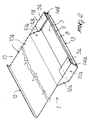
- a method for obtaining components for pieces of furniture, such as for example an access panel, a leaf or a door, hereinafter generally referenced as fronts, usable in particular for closing compartments temporarily, is described with reference to Figures 1 to 6.
- the reference numeral 1 designates a metal plate that is advantageously flat and is shaped so as to constitute a blank for obtaining a front, designated by the reference numeral 2, preferably for kitchen units.
- the flat metal plate 1 is provided so that its plan shape is advantageously approximately cross-like or T-like, and forms a flat body, designated by the reference numeral 3, that has one or more laterally protruding projections.
- the metal plate 1 has two first projections 4a and 4b that protrude laterally from the flat body 3, in a mirror-symmetrical position with respect to the longitudinal central axis of the metal plate 1.
- the first projections 4a and 4b are approximately rectangular and have first free ends 5a and 5b that protrude laterally and second free ends 6a and 6b that protrude downward.
- Two second lateral projections designated by the reference numerals 7a and 7b, also protrude from the metal plate 1 above the two first projections 4a and 4b and are also arranged mirror-symmetrically with respect to the longitudinal central axis of the metal plate 1.
- the second projections 7a and 7b are approximately triangular, with a free vertex that is orientated outward.
- a fourth projection 10 protrudes from the flat body 3 along its entire width and has an extension that is usually greater than the extension of the flat body 3.
- the method for obtaining the front 2 provides for performing a first bending of the first free ends 5a and 5b of the two first projections 4a and 4b so as to obtain two first lateral wings, designated by the reference numerals 11a and 11b, which are approximately L-shaped.
- the two second lower free ends 6a and 6b are subjected to bending along an axis that is perpendicular to the longitudinal central axis, so that said second free ends are arranged adjacent and at right angles to the first free ends 5a and 5b.
- the two second projections 7a and 7b thus constitute two second lateral wings, designated by the reference numerals 12a and 12b, which protrude above the first lateral wings 11a and 11b.
- a subsequent step provides for a fourth bending of the metal plate 1, which is performed at the third lower projection 8 and at the third free end 9 thereof, so as to obtain a third lower wing 13 that protrudes approximately at right angles to the flat body 3.
- the lateral edges 14a and 14b of the third wing 13 are thus arranged approximately at the lower edges of the two first wings 11a and 11b.
- Another step of the method described here provides for the bending of the fourth projection 10 along a plane that is advantageously oblique to the plane of arrangement of the flat body 3, followed by a further bending of said fourth projection in an opposite direction, so as to divide the fourth projection 10 into a first oblique portion 10a and a second portion 10b that is approximately co-planar to the plane of arrangement of the first free ends 5a and 5b of the two first wings 11a and 11b, as shown in Figure 2.
- Figure 2 also shows that a fourth free end, designated by the reference numeral 15, of the fourth projection 10 is subjected to bending at an angle of approximately 90°, so as to protrude approximately in the same direction as the third wing 13.
- a further bending of the second portion 10b of the fourth projection 10 is performed so as to obtain a flap, designated by the reference numeral 16 in the figures, that is advantageously arc-shaped and protrudes approximately in the opposite direction with respect to the third wing 13.
- the arc-like flap 16 is constituted by a double layer of metal plate, since it is formed by means of a double bending of the second portion 10b.
- Such bending is furthermore suitable to form a back wall 17 for the front 2; the back wall 17 is constituted by the part of the second portion 10b that is adjacent to the fourth free end 15, which as a consequence of said last bending is arranged at right angles to the flat body 3.
- the fourth free end 15 of the fourth projection 10 and the third wing 13 of the third projection 8 mutually overlap, so that they can be mutually associated by mechanical means of a known type, such as for example rivets 18.
- a component for pieces of furniture 1 such as a front that can be used for example as an access panel or leaf or drawer, which is formed monolithically by simple operations for bending a metal plate.
- the front 1 therefore has a box-like configuration, from the top of which user grip means, such as a handle constituted by the arc-like flap 16, protrude at the front.
- This method can be performed even by unspecialized personnel and by using machines that are simple and easily commercially available, such as plate bending machines and riveting machines.
- fronts that have a chosen shape and preset dimensions: such fronts can be closed or open at the rear, so as to be able to perform, for example, the insertion or foaming of insulating material.
- the resulting fronts have high characteristics of strength and durability over time: moreover, since they have no interstices, they allow to maintain an optimum level of hygiene during use.
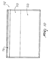
- the reference numeral 101 designates a metal plate that is advantageously flat and is provided so that it has, in plan view, an advantageously cross-like or T-like shape, so as to form a flat and rectangular body, designated by the reference numeral 103, that has one or more laterally protruding projections.
- the metal plate 101 has two first projections 104a and 104b that protrude laterally from the flat body 103, in a position that is mirror-symmetrical with respect to the longitudinal central axis of the metal plate 101.
- the first projections 104a and 104b are approximately rectangular and are provided laterally with first free ends 105a and 105b and, in a lower region, with second free ends 106a and 106b that are polygonal.
- Two second lateral projections designated by the reference numerals 107a and 107b, also protrude from the metal plate 101 above the two first projections 104a and 104b, are also arranged mirror-symmetrically with respect to the longitudinal central axis of the metal plate 101, and are approximately trapezoidal.
- An advantageously trapezoidal third projection designated by the reference numeral 108, protrudes downward from the flat body 103 and has a third free end 109 that is preferably rectangular.
- a fourth projection 110 protrudes from the flat body 103 along its entire width opposite the third projection 108 and has an extension that is usually greater than the extension of the flat body 103.
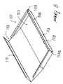
- the method for obtaining the front 102 provides for a double bending of the third free end 109 of the third lower projection 108 along an axis that is perpendicular to the longitudinal central axis of the metal plate 101.
- the third projection 108 can then be subjected to bending along an axis that is parallel to the preceding one and in the same direction, so as to obtain a third wing 113 that is approximately C-shaped and protrudes below the flat body 103.
- the bending of the second lower free ends 106a and 106b of the two first projections 104a and 104b can be performed advantageously simultaneously with the bending of the third projection 108 and therefore along the same axis as said third projection.
- the method further provides for a double bending of the first free ends 105a and 105b of the two first projections 104a and 104b and for the similar bending of the free end of the second projections 107a and 107b.
- the two first projections 104a and 104b and the second projections 107a and 107b are bent along an axis that is advantageously parallel to the longitudinal central axis, so that the second free ends 106a and 106b, bended earlier, overlap the lateral edges 114a and 114b of the third wing 113, so that they can be optionally mutually associated.
- Another step of the method described here provides for the bending of the fourth projection 110 along a plane that is advantageously oblique with respect to the plane of arrangement of the flat body 103, followed by a further bending, in the same direction, of the fourth free end, designated by the reference numeral 115, of the fourth projection 110, so that the fourth free end 115 protrudes approximately in the same direction as the third wing 113.
- the fourth projection 110 is bent again so as to obtain a flap, designated by the reference numeral 116 in the figures, that is advantageously arc-like and protrudes approximately in the opposite direction with respect to the third wing 113.
- the arc-like flap 116 is constituted by a double layer of metal plate, since it is provided by a double bending of the fourth projection 110.
- a component for furniture such as a front 101
- plastic material having good thermal insulation characteristics such as for example expanded polyurethane, is injected into the cavity designated by the reference numeral 120 in Figure 9 during mounting onto the frame or inner door.
Landscapes
- Engineering & Computer Science (AREA)
- Civil Engineering (AREA)
- Structural Engineering (AREA)
- Refrigerator Housings (AREA)
- Securing Of Glass Panes Or The Like (AREA)
Applications Claiming Priority (2)
| Application Number | Priority Date | Filing Date | Title |
|---|---|---|---|
| ITTV20020012 | 2002-02-05 | ||
| ITTV20020012 ITTV20020012A1 (it) | 2002-02-05 | 2002-02-05 | Procedimento per l'ottenimento di componenti per mobili particolarmente sportelli e/o ante e/o porte e prodotti cosi ottenuti |
Publications (2)
| Publication Number | Publication Date |
|---|---|
| EP1333146A2 true EP1333146A2 (fr) | 2003-08-06 |
| EP1333146A3 EP1333146A3 (fr) | 2004-08-04 |
Family
ID=11460159
Family Applications (1)
| Application Number | Title | Priority Date | Filing Date |
|---|---|---|---|
| EP03000526A Withdrawn EP1333146A3 (fr) | 2002-02-05 | 2003-01-09 | Procédé de fabrication de composants de meubles, particulièrement de panneaux d'accès, vantaux et portes et produits obtenus |
Country Status (2)
| Country | Link |
|---|---|
| EP (1) | EP1333146A3 (fr) |
| IT (1) | ITTV20020012A1 (fr) |
Cited By (2)
| Publication number | Priority date | Publication date | Assignee | Title |
|---|---|---|---|---|
| CN101548823B (zh) * | 2009-05-15 | 2011-02-09 | 朱建华 | 一种抽屉面板 |
| JP2012122628A (ja) * | 2010-12-06 | 2012-06-28 | Hoshizaki Electric Co Ltd | 貯蔵庫の断熱扉 |
Family Cites Families (4)
| Publication number | Priority date | Publication date | Assignee | Title |
|---|---|---|---|---|
| FR1255212A (fr) * | 1960-04-21 | 1961-03-03 | Desoer Sa | Meuble à tiroirs |
| GB1211110A (en) * | 1968-05-10 | 1970-11-04 | P C A Data Proc Accessories Lt | Improvements in trays for filing cabinets |
| FR2494954A1 (fr) * | 1980-11-25 | 1982-05-28 | Electro Mecanique Ste Indle | Nouvelle armoire metallique |
| GB2123467B (en) * | 1982-05-04 | 1985-11-27 | Randalls Of Paddington | Sheet metal panel |
-
2002
- 2002-02-05 IT ITTV20020012 patent/ITTV20020012A1/it unknown
-
2003
- 2003-01-09 EP EP03000526A patent/EP1333146A3/fr not_active Withdrawn
Cited By (2)
| Publication number | Priority date | Publication date | Assignee | Title |
|---|---|---|---|---|
| CN101548823B (zh) * | 2009-05-15 | 2011-02-09 | 朱建华 | 一种抽屉面板 |
| JP2012122628A (ja) * | 2010-12-06 | 2012-06-28 | Hoshizaki Electric Co Ltd | 貯蔵庫の断熱扉 |
Also Published As
| Publication number | Publication date |
|---|---|
| ITTV20020012A1 (it) | 2003-08-05 |
| EP1333146A3 (fr) | 2004-08-04 |
Similar Documents
| Publication | Publication Date | Title |
|---|---|---|
| KR102950634B1 (ko) | 냉장고 | |
| CN108351154B (zh) | 包括门框架和凹入式把手元件的门及包括这种门的家用制冷器具 | |
| US10208963B2 (en) | Cooking appliance | |
| JP2009541699A (ja) | 隠しヒンジを有する家電製品 | |
| EP2889566B1 (fr) | Structure de porte pour un dispositif de réfrigération | |
| EP0565900A1 (fr) | Charnière pour appareils frigorifiques, en particulier pour réfrigérateurs et analogues | |
| US6629339B2 (en) | Refrigerator handle mounting arrangement | |
| US20150027429A1 (en) | Frame structure for an appliance | |
| US7845189B2 (en) | Door for a refrigeration device | |
| EP1333146A2 (fr) | Procédé de fabrication de composants de meubles, particulièrement de panneaux d'accès, vantaux et portes et produits obtenus | |
| KR200453259Y1 (ko) | 슬라이드식 단자함 커버덮개 | |
| US20150351541A1 (en) | Assembly Kit and Door Assembly for Appliance | |
| CN208959332U (zh) | 冰箱 | |
| GB2040162A (en) | Fitted kitchen furniture | |
| US20200018539A1 (en) | Method and Apparatus for Sealing French Doors for a Freezer Compartment | |
| CN101795603B (zh) | 家用制冷电器 | |
| JP6654082B2 (ja) | 収納ユニット | |
| KR20190097383A (ko) | 폴딩도어 | |
| US7401489B2 (en) | Method of forming a one-piece frame for a cantilevered refrigerator shelf | |
| CN101431918B (zh) | 用于嵌入式器具的家具布置 | |
| JPS637680Y2 (fr) | ||
| CN215408258U (zh) | 一种新型具有抗变形功能的衣柜门板 | |
| CN223826609U (zh) | 家用电器 | |
| EP0706019A2 (fr) | Porte pour meuble commercial | |
| CN217812828U (zh) | 自由开合扇形拉手 |
Legal Events
| Date | Code | Title | Description |
|---|---|---|---|
| PUAI | Public reference made under article 153(3) epc to a published international application that has entered the european phase |
Free format text: ORIGINAL CODE: 0009012 |
|
| AK | Designated contracting states |
Designated state(s): AT BE BG CH CY CZ DE DK EE ES FI FR GB GR HU IE IT LI LU MC NL PT SE SI SK TR |
|
| AX | Request for extension of the european patent |
Extension state: AL LT LV MK RO |
|
| PUAL | Search report despatched |
Free format text: ORIGINAL CODE: 0009013 |
|
| AK | Designated contracting states |
Kind code of ref document: A3 Designated state(s): AT BE BG CH CY CZ DE DK EE ES FI FR GB GR HU IE IT LI LU MC NL PT SE SI SK TR |
|
| AX | Request for extension of the european patent |
Extension state: AL LT LV MK RO |
|
| 17P | Request for examination filed |
Effective date: 20050125 |
|
| AKX | Designation fees paid |
Designated state(s): AT BE BG CH CY CZ DE DK EE ES FI FR GB GR HU IE IT LI LU MC NL PT SE SI SK TR |
|
| 17Q | First examination report despatched |
Effective date: 20070423 |
|
| STAA | Information on the status of an ep patent application or granted ep patent |
Free format text: STATUS: THE APPLICATION IS DEEMED TO BE WITHDRAWN |
|
| 18D | Application deemed to be withdrawn |
Effective date: 20071105 |